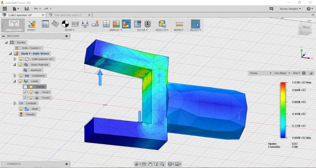
Nice work Grant! There's some interesting stuff in F360, especially when you consider it's free for the likes of us. Sounds as if it may be a bit premature to talk about the CAM elements that are waiting for you but there is some interesting content in the "simulation" tab too. Here you can do full Finite Element Analysis (FEA) to see how close to the bone the design is with the sorts of loads you might expect to see.
If you take your existing design and create some small features to denote where the spanner will contact the nut, you can apply some contact forces and simulate the stresses and strains that represent what the spanner will see in the worst case – will it be close to failure, is there a weak area where there is undue stress etc.
It's under Simulation > Study > Static stress. You place loads, constraints (fixed faces for instance) and set materials (aluminium jaws and steel handle here), then click Solve. You can display stress, strain, displacement etc.
I haven't taken long to model your tool very accurately (it's really not very close) but this gives an idea of how quick and easy it is to do some FE Analysis. My jaws were 25m wide and 15mm thick, so probably not as beefy as yours.

The end of the handle is fixed and I assumed a torque of 5Nm (3.8lbft) and a nut dimension of 44mm A/F. With a hex head this results in equal and opposite forces of almost 1400N at the line contacts between the nut and the jaws (1400N x 36mm = 5Nm) – these are the blue arrows.
The yield stress of aluminium is around 15-20 MPa, so in my example where it predicts about 70MPa peak stress, the jaws would have turned to toffee. You can see where the highest stress is – and where it would be possible to beef up the section to improve it.
Hope you find this interesting!
Murray
Edited By Muzzer on 16/01/2016 18:35:41
Muzzer.


