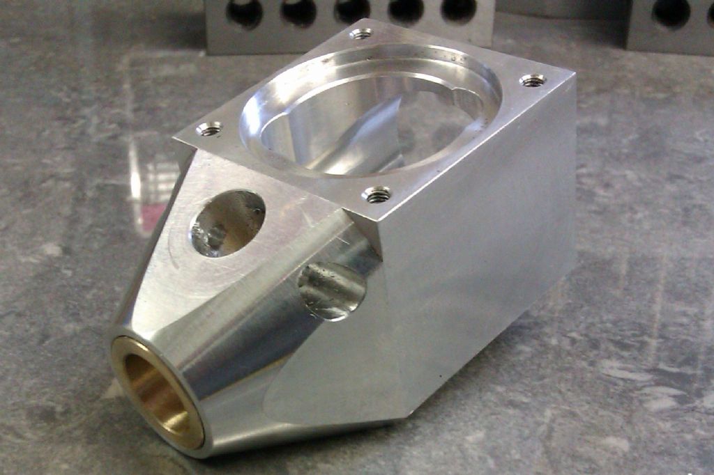
Firefly .46 crankcase

Advert

Firefly .46 crankcase

Home Forums Model Engineer. Firefly .46 crankcase

Viewing 25 posts - 26 through 50 (of 57 total)
  • Author
    Posts
  • #92514
    _Paul_
    Participant
      @_paul_
      Posted by JasonB on 13/06/2012 20:37:51:

      Anyway for any beginners who want to make a start and are not quite sure I've added a few photos to a new album that I have created which may come in handy. Just click ## photos under my avitar.

      J

      I really quite fancy building the Firefly, Jason your pictures are tidy and paint a thousand words do you plan to take more? trust me it will be appreciated.

      Regards

      Paul

      Advert
      #92517
      JasonB
      Moderator
        @jasonb

        David, yes I got a couple of hours in the workshop tonight and that's how far I got.

        Paul, yes I expect I will photograph it all, maybe do a build diary on HMEM or here if there is a demand.

        J

        #92539
        john kennedy 1
        Participant
          @johnkennedy1

          You dont hang about do you.I'll hopefully cast some blocks at the weekend,weather permitting.Good photos,keep going…

          #92543
          David Clark 13
          Participant
            @davidclark13

            Reply from Frank

            Guilty as charged, I misread the 30mm pitch for the tapped holes as the bore diameter.
            As far as the 25mm hole kissing the face, this was included to ensure that the 25mm bore is in the correct position with regards to the main bore (28.2mm) and thus ensures that the Cylinder liner is lined up with the Crankpin. Having looked at the drawing again, it does show that the 25mm bore is machined into the 30mm bore as far as it will go (although I would have thought that this was obvious) and it does line up with the bottom of the main bore.

            As far as the chamfers are concerned, there is a deliberate degree of latitude for individual choice, but it is correct that there is no specific dimension. For the purposes of this enquiry, I suggest that the chamfer should extend 22mm from the front face. Perhaps the other builders made their own decision!

            #92546
            JasonB
            Moderator
              @jasonb

              Thanks for the confirmation David/Frank.

              J

              #92551
              Sub Mandrel
              Participant
                @submandrel

                Took me longer than usual to 'read' the drawing and figure out what this is about – the dimensions are crowded and most, but not all, of the bores are specified from the cross section, but one is from its end view.

                The side chamfers in the plans and the 3d views in the article do appear to consistently extend less far back than the top one, but there's no immediately obvious reason why.

                Neil.

                #92552
                JasonB
                Moderator
                  @jasonb

                  The dimensions are not really that cramped, you need to allow for the fact that they have been reduced down from A3 to A4 to fit in the mag. Best to download them from Alex's site and blow them upto what you want.

                  I think the nose chamfers on the sides & bottom are for aerodynamic looks while the steeper top 20deg suits the intake angle of 70deg allowing the carb to fit at right angles to the surface.

                  J

                  #92559
                  David Paterson 4
                  Participant
                    @davidpaterson4

                    Hi Jason,

                    Like the photos. In the second you caption 'clockiing true'.

                    Is this to position the centre of the face for drilling, or to align the axis of the block true with the axis of rotation?

                    if the latter, how? – seems like a good idea and an tis point of learning I sort of rely on having the ends parallel and tappping the block onto the face of the chuck to achieve this. Looking for a better approach for stuff that is neither round nor long enough to take readings from two points along the length out from the jaws.

                    #92561
                    JasonB
                    Moderator
                      @jasonb

                      Its to position the previously marked & punched centre mark, much the same as the photo of me locating the 25mm hole.

                      But as there is quite a bit of metal sticking out of the chuck and the end nearest the chuck is just the sawn finish you can't rely on just the chuck jasws to ensure the block is aligned to the lathe axis. Easiest way to check is to hold the stock of a tri square against the chuck face and the blade against the work, you will need to do this on two adjacent faces and also two or 3 times as you adjust the position of the centre as the action of loosening & tightening the jaws could throw the work off. You could also run a dti along the sides to check but a good square does the job.

                      If the face that is going towards the chuck is square to the sides then it is possible to sit the work onto the chuck face provided it larger than the hole in the chuck, did this for the 25mm bore setup.

                      J

                      #92575
                      David Clark 13
                      Participant
                        @davidclark13

                        Hi There

                        I print out the drawings to the aproximate size in the magazine and then decide if they are readable at that size before publishing. I have options of A3, A4 or A5.

                        regards David

                        #92594
                        JasonB
                        Moderator
                          @jasonb

                          Bit more progress, another 16 photos in the albumnerd

                          J

                          #92599
                          Gone Away
                          Participant
                            @goneaway
                            Posted by Andrew Johnston on 12/06/2012 19:51:20:

                            I've been using 3D PDFs to send parts to clients for some years; so far I've never found a way to make measurements. The PDF files are smaller than the native part files by about an order of magnitude. I assume the PDFs define the part in a way that does not allow measurement?

                            Don't know if it helps but there are some measurement settings for 3D in Edit > Preferences in Acrobat At least in my versions (Reader Version – X; Full Acrobat Version – 8)

                            #92754
                            JasonB
                            Moderator
                              @jasonb

                              Thanks david I spotted it straight after I submitted the post so removed that part, you obviously saw it the moment I posted.

                              J

                              #92755
                              David Clark 13
                              Participant
                                @davidclark13

                                Hi Jason

                                All posts are emailed to me as they are posted.

                                Not here all the time but check regularly from 8 am to 10 pm.

                                regards David

                                #92838
                                EtheAv8r
                                Participant
                                  @etheav8r
                                  Posted by JasonB on 13/06/2012 20:37:51:

                                  Its a shame that there are not more photos of the build to go along with the description, hopefully there are some to follow David?

                                  Anyway for any beginners who want to make a start and are not quite sure I've added a few photos to a new album that I have created which may come in handy. Just click ## photos under my avitar.

                                  J

                                  Edited By JasonB on 13/06/2012 20:38:52

                                  Jason

                                  Thank you so very much for taking the time and effort to post your photos and produce an effective build guide blog. I have the materials to make two of these, but as a beginner I have found your blog to be heaven-sent and it makes the process so clear and 'do-able' for those like me.

                                  Edmund

                                  #92842
                                  David Clark 13
                                  Participant
                                    @davidclark13

                                    Hi There

                                    I have some more photos to go through.

                                    They are ready for me to download.

                                    regards David

                                    #92861
                                    JasonB
                                    Moderator
                                      @jasonb

                                      Good to hear the photos are of Use Edmund, I'm sure there are other ways of doing things depending on what you have to hand if you do have any queries just ask. I've added a few more tonight.

                                      David look forward to seeing the other set of photos.

                                      J

                                      #92868
                                      Wolfie
                                      Participant
                                        @wolfie

                                        I'm glad to read this thread cos I've just spent half an hour wondering where the hell the 30mm diameter is. I was just about to post on the beginners section about it when the new format drew me to this thread. Score one for the new format.

                                        #92945
                                        JasonB
                                        Moderator
                                          @jasonb

                                          Well the crankcase and bearing are complete all bar a bit of blending and final cleaning up but that will have to wait until all the other parts are complete. I went my own way slightly with teh nose chamfers and turning. There are some more photos of the final stages in my album.

                                          I think I will start another thread about teh build so it does not get lost in this one which is really about article errors & omissions.

                                          Firely40


                                          J

                                          Edited By JasonB on 22/06/2012 21:02:24

                                          #92977
                                          EtheAv8r
                                          Participant
                                            @etheav8r

                                            A separate "clean" thread detailing the build woud be a super resource, so here is one vote for "Yes please"!

                                            edmund

                                            #92978
                                            Chris machin
                                            Participant
                                              @chrismachin

                                              And has already been mentioned , here's another 'yes' for a build thread…….Please..wink

                                              Chris

                                              #92979
                                              JasonB
                                              Moderator
                                                @jasonb

                                                OK I'll get it going.

                                                Just added some more photos of the barrel.

                                                J

                                                #93056
                                                Terryd
                                                Participant
                                                  @terryd72465

                                                  Hi all,

                                                  Sorry to hijack this thread but the question is sort of pertinent to the engine and I don't want to start a whole new thread.

                                                  I am beginning a build of Firefly and I have most of the materials to hand but I have no source of Dural for the con rod. I have looked on the website of most suppliers I use, but no luck and a Google question just gets me to industrial supopliers. As I only need a small piece can anyone suggest a source or an readily available alternative material. This is my first i.c. engine so am usure of the requirements.

                                                  Thanks for reading and sorry again Jason for this hijack,

                                                  Best regards

                                                  Terry

                                                  #93060
                                                  Anonymous

                                                    Terry,

                                                    A roughly equivalent aluminium/copper alloy is 2014, available in small quantities from M-Machine in the UK. The 2xxx alloys can be prone to stress corrosion cracking, so in the aerospace industry they're being replaced by 7xxx alloys, the most common of which is 7075. However, 7075 is more difficult to get in small quantites, and is a bit more difficult to machine.

                                                    Regards,

                                                    Andrew

                                                    #93062
                                                    Versaboss
                                                    Participant
                                                      @versaboss

                                                      Terry, I can't help you with a supplier, but what you need is an Aluminium alloy from the Al-Cu-Mg group, with around 4 % Copper. Other brand names are Avional, Aludur. For more informations consult Wikipedia.

                                                      The table under DIN 1725 gives the appropriate W-numbers, if these can help you…

                                                      Here it is: http://tinyurl.com/6o45y4z

                                                      Greetings, Hansrudolf

                                                    Viewing 25 posts - 26 through 50 (of 57 total)
                                                    • Please log in to reply to this topic. Registering is free and easy using the links on the menu at the top of this page.

                                                    Advert

                                                    Latest Replies

                                                    Home Forums Model Engineer. Topics

                                                    Viewing 25 topics - 1 through 25 (of 25 total)
                                                    Viewing 25 topics - 1 through 25 (of 25 total)

                                                    View full reply list.

                                                    Advert

                                                    Newsletter Sign-up