Feed trip electronic

Advert

Feed trip electronic

Home Forums Electronics in the Workshop Feed trip electronic

Viewing 10 posts - 1 through 10 (of 10 total)
  • Author
    Posts
  • #570977
    Speedy Builder5
    Participant
      @speedybuilder5

      With the various Electronic Leadscrew projects, is / are there any which incorporate a feed stop, especially for threading. I appreciate that doing this on threading, the stepper would loose synchronisation with the headstock spindle, but there must be a clever way of re-synchronising?

      Bob

      Advert
      #32221
      Speedy Builder5
      Participant
        @speedybuilder5

        Understanding the electronic leadscrew.

        #570980
        John Haine
        Participant
          @johnhaine32865

          I think they will all have to resynchronise – after all they have to initially sync so just have to repeat it.

          I use Mach3 which has a 1 pulse per rev sensor, it places the tool in a known position just clear of the work, then when it sees a spindle pulse it accelerates the tool at a known rate up to the required feedrate, so it will have moved a known precise distance by the time it meets the work. This is just repeated many times as the thread is cut to the required depth. It does rely on the spindle speed staying constant both between and within cuts but on my lathe (S7) this isn't a problem as long as you're not over ambitious.

          Linux CNC does something similar, but also monitors and controls spindle speed during the cut. It needs a second high-res encoder to do this. Other CNC controllers work similarly.

          So any ELS system just needs to emulate one of these controllers to work.

          You could ask why use an ELS at all when you could use CNC – I couldn't possibly comment.

          #570981
          Tony Pratt 1
          Participant
            @tonypratt1

            I'm using the Clough42 electronic lead screw with much success, I'll send him a mail to ask if he can look at it.

            Tony

            #570983
            Tony Pratt 1
            Participant
              @tonypratt1
              Posted by John Haine on 12/11/2021 13:32:33:

              I think they will all have to resynchronise – after all they have to initially sync so just have to repeat it.

              I use Mach3 which has a 1 pulse per rev sensor, it places the tool in a known position just clear of the work, then when it sees a spindle pulse it accelerates the tool at a known rate up to the required feedrate, so it will have moved a known precise distance by the time it meets the work. This is just repeated many times as the thread is cut to the required depth. It does rely on the spindle speed staying constant both between and within cuts but on my lathe (S7) this isn't a problem as long as you're not over ambitious.

              Linux CNC does something similar, but also monitors and controls spindle speed during the cut. It needs a second high-res encoder to do this. Other CNC controllers work similarly.

              So any ELS system just needs to emulate one of these controllers to work.

              You could ask why use an ELS at all when you could use CNC – I couldn't possibly comment.

              CNC conversion is a load more work.cheeky

              Tony

              #570990
              Joseph Noci 1
              Participant
                @josephnoci1
                Posted by Speedy Builder5 on 12/11/2021 13:10:23:

                With the various Electronic Leadscrew projects, is / are there any which incorporate a feed stop, especially for threading. I appreciate that doing this on threading, the stepper would loose synchronisation with the headstock spindle, but there must be a clever way of re-synchronising?

                Bob

                Do you mean a physical stop, ie, a forced hard stop? There is no technical reason you cannot just do that – most useful ELS's allow the user to set the thread start point and end point by various means – start and end by jogging to those point and indicting start and end, indicate start and number of threads, etc. The one I designed I jog to start, press start button, jog to end and press end and then go. But, I could set the start point, and then set the end point say 100mm down the shaft, while I only want a threaded section of 10mm long. I could then place a feed clamp on the bed at the 10mm position. When the carriage hits that, the stepper will stall and you stop the process, go back to start and repeat.

                You do need to size the stepper and it's torque carefully though – it must stall gracefully and not wind up the leadscrew…

                The system will always self-synchronize – it uses the index pulse on the spindle encoder to know where the carriage needs to be in relation to the thread start point.

                The value of CNC'ing the lathe depends on your needs – most often, if it's your only lathe, it's then a pain as every job you do needs the computer turned on, you need to create the G code – for it to be quick and not an impediment to small off-hand jobs you should have a really good conversational CAM package to generate the Gcode. Also, if you don't use it that often, memory will make it more frustrating as well. Its not the same ease as chucking a piece of shafting, taking a cut and measuring till it's right…

                You can fit electronic handwheels to X and Z, but I hate them – they do not have the same feel by far, offer no resistance to hand force by which you judge the cutting force, and by which you 'smooth' out the hand feed, etc.Just rubbish, those handwheel.

                Joe

                #571006
                Speedy Builder5
                Participant
                  @speedybuilder5

                  Yes Joe, a HARD stop is not so good although it seems that most systems START with a hard start ! When I wrote the code for an Arduino X axis one the mill, I wrote a SOFT stop/start and JOG into the code as otherwise it seemed a bit brutal.

                  OK, so there should be an Index pulse on the spindle, so that is sorted.

                  The carriage in relation to the leadscrew – could this be set by a second electronic (microswitch or other) stop at the start of the workpiece. So we know the start point, the software needs to know to always start on a spindle index pulse and stop on the feed stop.

                  So, in action, move the carriage to a point before the start of the workpiece and advance the right hand stop to this position.

                  Move the carriage to the feed stop position and set the left hand stop.

                  Engage the half nut and keep engaged.

                  Setup the ELS (Electronic Lead Screw) for the thread / feed required.

                  Return the carriage to the Right hand stop by use of the ELS.

                  Set the in-feed of the topslide and hit GO !

                  To return the carriage, back off the top slide and reverse the ELS.

                  The main problem that I see is how to get an accurate start point without a second encoder. Also, backlash between the leadscrew and half nuts.

                  Over to you guys.

                  Bob

                  #571015
                  Joseph Noci 1
                  Participant
                    @josephnoci1

                    Bob,

                    You don't need a second encoder – lets take a look at the basics of most ELS systems.

                    Using an ABZ encoder which has an A and B quadrature channel pair , and a Z or index channel is how most ELS systems do it.

                    The index is used by the ELS to sync the leadscrew stepper so the threading tool enters the workpiece at the same place each time. So it does not matter where the tool tip is placed in relation to the work piece – ideally it is position a few thread pitches from the thread start. But is does not have to be the same position each new threading pass. So you could set it say 10mm from the start, do a pass, then return and stop say 5mm from the start and it will still be OK. As long as the halfnuts are kept engaged, the ELS will wait for the index pulse, and then in the space leading to the thread start in the workpiece, it will accelerate the leadscrew stepper such that the leascrew is at the correct speed ( for the spindle speed and chosen thread pitch) and at the correct position when the tool tip enters the workpiece.

                    The AB channels ( you can get away with only A in you never thread in reverse..) are generally a high number or pulses per spindle rev – around 2000 to 4000 or so pulses. These pulses are used to generate the stepper pulses ( and pulse rate) via a divider or via Bresenham's given the desired thread pitch and spindle RPM, which is measured by means of said encoder. Likewise, it does not matter where the thread end is – you only need it to be in the same place each time , esp if threading to a shoulder.

                    In reality is is a simple task for the ELS to keep track of the thread end, thread start, threading in process and threading done mechanisms, so having hards stops, or any other form of stop is superfluous.

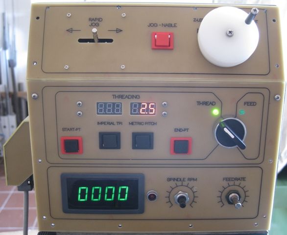
                    mine works as follows –

                    Set tool tip at thread start point, say 6mm from the shaft end. Press Thread_Start. Jog ( Via ELS button or handwheel) the tool tip to the thread end position, press thread end. An led lights up, indicating 'go to thread start' Press button to go to start – carriage rewinds to start. An led lights indicating ;Start Threading'.

                    Start the spindle, press 'Start Threading' button, with depth of cut set.

                    Tool reaches thread end, carriage halts. Retract tool, prees 'go to start' button, carriage returns to start position and repeat.

                    I use a jog wheel to set the start and end points and to select thread pitch etc..

                    Threading with ELS can become 'boring' – no more butt_clinching, so it needs to be simple to use, no complex settups, etc – all so you don't get sequences wrong cause you are thinking of other things..

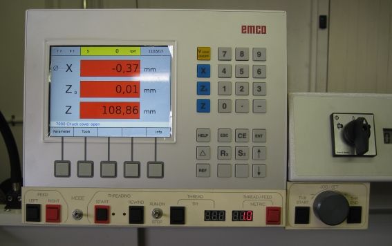
                    ELS is long narrow panel below the DRO.

                    els panels1.jpg

                    This is the same ELS system, fitted to my smaller EMCO lathe.

                    threading 2.5mm pitch setup_0861.jpg

                    #571041
                    Bazyle
                    Participant
                      @bazyle

                      Joseph's system above is rather more sophisticated than most in using a high count/rev encoder and taking the time/trouble to set up the length of thread initially.
                      I suggest that for many systems what is missing is some way of telling it the desired length of thread so it can just do that many steps then stop pulsing. Should be easy to add.
                      Then when would back to the start how accurate is your switch – one, two, three thou? Having the stepper 'unwind' the same number of steps may be a nice option all depending on not missing a step during acceleration.
                      A one pulse per rev system needs one detector. A multi pulse needs both a pulse counter and a top dead centre indicator so starts to get more complicated. (though you can use the double slit encoder to get round this in some ways).

                      #571054
                      Martin Connelly
                      Participant
                        @martinconnelly55370

                        Tony P 1

                        I would have to say that a two motor ELS setup is far more work than a 2 motor CNC setup. I have looked at what is involved with making and programming an ELS and it is not an easy task. Since you can use turning wizards with Mach3 there is no need to learn CAD/CAM or Gcode to use it.

                        This video shows what is needed for Mach3, most of it is shared with and ELS and the old second hand laptop is perfectly adequate and cheap. The only thing missing for threading is a suitable sensor which costs a few pounds on the internet.

                        In Mach3 to cut a thread with the threading wizard you input start diameter (or radius if that is how you have it set up), end diameter (radius), pitch, start z value (position along the bed), end z value, spindle speed, pass depth, final pass depth angle over which the tool is retracted and number of spring passes. You can set the infeed angle, minimum pass depth and some other parameters in the settings to suit your usual needs. A mini remote keyboard makes a good pendant.
                        No need for a gearbox or change wheels. Metric and imperial threads can be cut.
                        Martin C
                      Viewing 10 posts - 1 through 10 (of 10 total)
                      • Please log in to reply to this topic. Registering is free and easy using the links on the menu at the top of this page.

                      Advert

                      Latest Replies

                      Viewing 25 topics - 1 through 25 (of 25 total)
                      Viewing 25 topics - 1 through 25 (of 25 total)

                      View full reply list.

                      Advert

                      Newsletter Sign-up