There is bound to be confusion for some in this thread – due to the term 'Diamond tool'. Makers of jewellery, watch cases, and alloy wheels for cars use diamond tools tipped with real diamonds. I suggest that this thread is dealing with an Australian tool holder (which does excellent work) but that is only a trade name, it is made from steel, and holds steel tool bits – no jewels are involved. It is a shame that this sort of muddle is created in the search for whizzy names. No wonder there are folk who just hate marketing.
As I said there is nothing wrong with the diamond type tools and they certainly make it easy to grind a tool that is almost certain to work but don't think they will mean you can shift metal at production rates using them.
Having now watched to the end he does say 200thou off dia and 100thou infeed, also says on that 100thou cut that the amps he was pulling suggest he was using all of the available 5hp of what looks like a geared head lathe, you will be lucky to have 20% of that from the 250.
I would certainly not dispute that but it demonstrates that the tool does take a lot more than you originally indicated. The grade of steel used has a bearing. The video is working on stainless & that is a bit harder than most of the stuff I turn . However, as suggested by journeyman above , one has to start slowly & build up.
Thanks for the comments re feeds. i need to find the casing for the change wheels. it was (along with the chuck guard) the first thing I discarded when i installed the lathe, On the front should be the plate with change wheel configurations for feeds.
In taking the cover off, I have been able to wire the safety lock to a micro switch on a carriage stop which i find very useful
I will try the paper between gear tooth trick, The gears do rattle against each other. I do not have room for any washers. The whole assembly is poor. I had to obtain a 14mm reamer before I could even get the gears to fit the shafts
I sometimes regret buying this lathe– as they say " the bitterness of poor quality lingers long after the thrill of low price is forgotten.
Sam I did not say any figure for what the tangental or any HSS too for that matter could remove. What I did say is that the slower surface speed needed for HSS would mean you will need to run about 1/3rd the speed of carbide and therefore it will remove 1/3rd the volume in the same time given similar DOC and feed. If that was carbide in the video it could have been run at 1500-2000rpm on that 1/2" bar . That still holds true and once you fully understand the relationship of surface speed, feed and DOC you will see why.
Don't you have the manual as that also has the chart in it.
As Journeyman says the 250 comes with washers just as my 280 does so you should have them and the room to fit them. they go between the paired gear's stud and the banjo, I'll take a photo tomorrow to show where they go and how they affect the sideways spacing of the gears.
Jason makes the very good point that it is unrealistic to to expect a small machine, such as 450 watt mini lathe to remove metal at the same feeds and speeds as a larger, heavier and more rigid machine with a more powerful motor.
The manual for my mini lathe errs very much on the side of caution, by advising 0.010" (0.25 mm ) as a roughing cut!
With regard to the Diamond Turning Tool. To most model engineers this would mean a Tangential Turning Tool. Diamond being the trade name applied to one marketed by an Australian Company, and imported into UK, rather than a tool with a mineral diamond tip.. Such tools do exist and are used in industry for high spec, high precision turning on such things as I C Engine pistons
Tangential tools are highly thought of by those whom have experienced them. For many, that has become their general purpose turning.tool. The "Diamond" nomenclature stems for the fact that when sharpened, by grinding the square HSS toolbit at an angle, a diamond (Lozenge ) shaped face results.
By all means find the gear cover and refit it it, if only for the sake of safety and cleanliness. Those are among the reasons why the manufacturer went to the trouble and expense of providing it!
The table will provide details of the gear trains to set for various threads and feed rates. By acquiring extra gears, it will be possible to set up trains for further variants.
(My lathe says that the coarsest pitch that can be cut is 3 mm By replacing the normal 40T input gear to the Norton box with a 30T (supplied with the lathe! ) it was possible to cut a 4 mm pitch thread for a p;articular job..
Similarly, a mini lathe, with a Metric Leadscrew, can cut Imperial threads, (or vice versa ) by including a 63T gear in the train. It is not as precise a using a 127T, but the errors are acceptable for many purposes. .
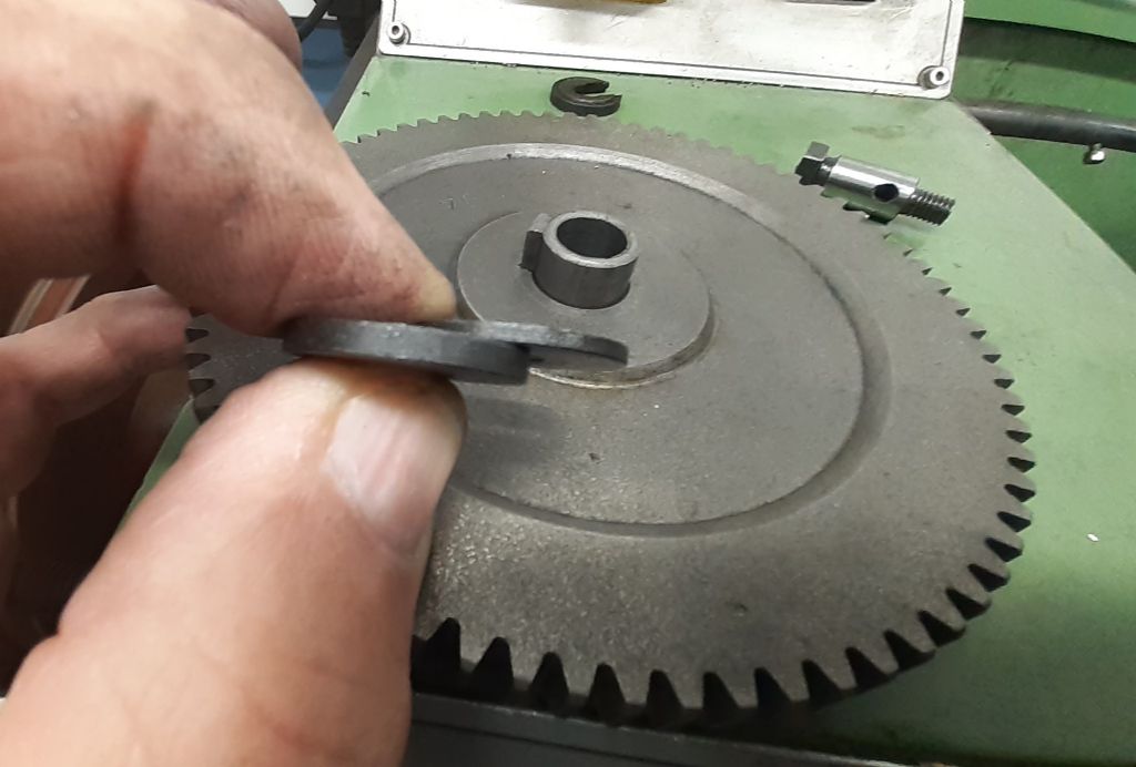
Setting the gears by with a sheet of paper in each mesh will provide acceptable backlash, to drastically reduce noise and wear. Using a thick gear lubricant will further improve matters, and this is where the gear cover comes into it own, in containing any lubricant that is flung from the gears.
Don't despair, when you become familiar with the machine and how to set it up, you will find that can be a very useful tool.
It may not be perfect, hardly any any machine is. There will always be a job that is not ideal for it or is impossible to do on it. You can't swing a 150 mm job on a non gap bed machine with a 100 mm swing over the bed.
But, you will be amazed at what a skilled operator can do on a fairly modest machines!
At the other extreme, today, I have thinned the head of 10 BA bolts, held in 6 a inch 3 jaw chuck, on a machine capable swinging 12" over the bed! . Looks ridiculous, but the chuck can 10 BA nuts!
Learn how to get the best from your machine before damning it. The Industrial Revolution grew using machines far less sophisticated than your!
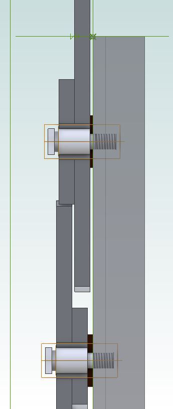
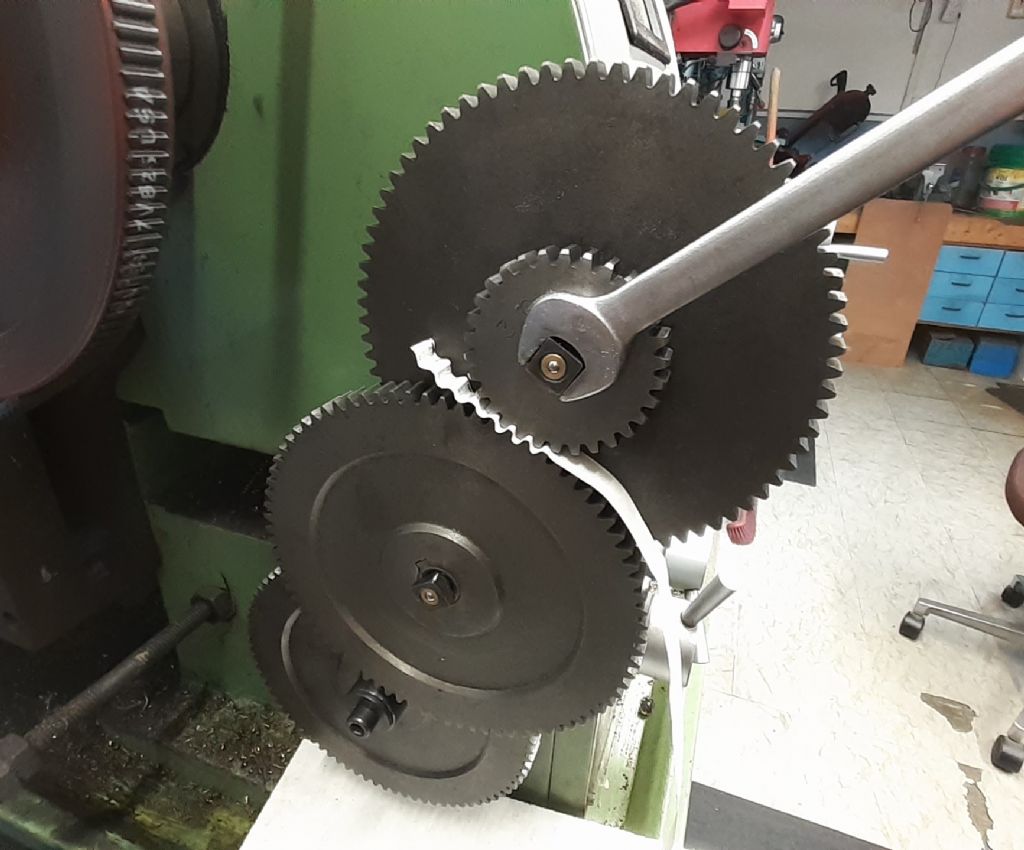
Image shows how having the correct thicker washer (black) on the lower pair of gear's stud moves them away from the pair above with the smaller washer. gap = difference in washer thickness
I don't know if the lathe came to you second hand without them or they have been missplaced but if you don't have them in place that will be why you have noisy gears
You might want to check how much thread engages when the studs are screwed in place. Mine often unscrewed, because only 3 or 4 threads did anything, and eventually stripped after about 5 years use. I made new ones, better finished and with slightly longer threads, from an aircraft bolt. They actually fit properly and I don't worry about them coming loose part way through a job.
I should make new keyed spacers at some point, as they're the next weak link.
I don't consider these to be real problems, as they only became apparent after several years use.
I will check that there is room for the washers & still fit the "circlips" ( for want of a better term) without them flying out
Sam they won't affect how the gear bush fit son the stud. The washers are 6mmID and only go onto the small M6 threaded spigot therefore moving the whole stud sideway
Not had a problem with mine coming loose and threads still holding after 12-13yrs,
Posted by Nicholas Wheeler 1 on 05/11/2021 22:45:36:
You might want to check how much thread engages when the studs are screwed in place. Mine often unscrewed, because only 3 or 4 threads did anything, and eventually stripped after about 5 years use. I made new ones, better finished and with slightly longer threads, from an aircraft bolt. They actually fit properly and I don't worry about them coming loose part way through a job.
I should make new keyed spacers at some point, as they're the next weak link.
I don't consider these to be real problems, as they only became apparent after several years use.
Surely any sensible design would have shouldered studs, such that they screw in exactly to the shoulder and tighten exactly at that point? Anything less seems to be yet another cheap short cut, on top of fitting ‘circlips’ to secure the gears/gear-pairs. Should there be a washer between the circlip and gear, too? I would expect that to be necessary to control end-float.
On my ancient lathe, the studs are designed properly – allowing a precise length of hardened, machined stud available for the gears to run on. Proper (thick) washers actually secure the gears in position, the threads on the outer end of the gear stud being female, thus accepting a set screw which is screwed up tight.
As an aside, with this old design, the thick washer is slotted so that it can be removed after only loosening the setscrew, allowing the gears to be replaced without actually complete removal of the fixing. Not too clever for the chinese to copy? No, but more expensive for a proper design (that works).
These are all small, but valid, reasons why ‘old iron’ is better than cheap modern chinese machines – as long as the old machine is not worn out to the point of ‘boat anchor’ status.
Looking at Jason’s pic and Sam’s description, have they cheapened the system in the last decade?
Surely any sensible design would have shouldered studs, such that they screw in exactly to the shoulder and tighten exactly at that point? Anything less seems to be yet another cheap short cut, on top of fitting ‘circlips’ to secure the gears/gear-pairs. Should there be a washer between the circlip and gear, too? I would expect that to be necessary to control end-float.
That's what they were aiming for. My new ones do. But the original studs weren't very well made, and eventually failed after several years use.
Most of the hardware is low quality which is a peculiar place to save money, as good quality nuts/bolts/etc are dirt cheap even when bought in small quantities. That said, if the compromise is to replace easy, small parts after a few years use or have to fix the actual machine(which is more than good enough for its intended use) I know which I prefer.
Having separate washers allows you to swap them about depending on the gear train, some trains need the pair to one side some the other,
NDIY if you care to look at my images you will see the studs DO HAVE shoulders so there is a set length for the sintered bush to run on Stud is slightly longer than bush just like yours too..
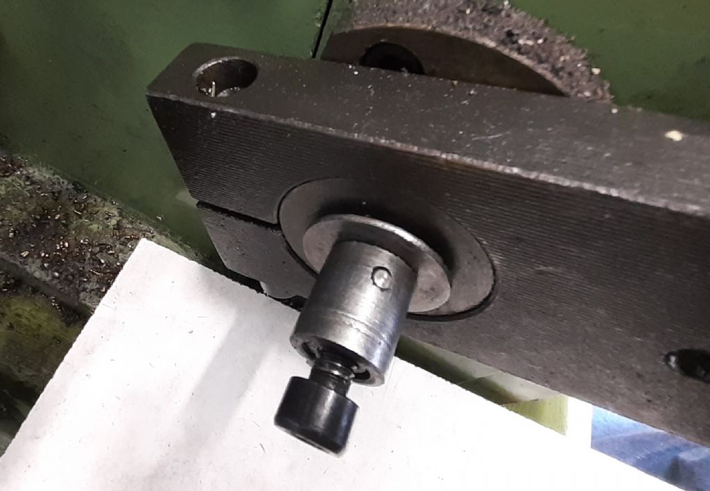
They are more recessed "C" clip with what would act like an integral washer, so not as poor a design as your blind comment suggests. These washers just like yours can be slid off without loosening or removing anything so gears can be taken off while studs remain in position which sounds as good a design as yours
The spacer washers are thick washers, 1.5mm for the thin and 2.5mm for the thick not just cheap penny washers, not file tested them for hardness.
Few Photos for you Sam, my 280 but your 250 is basically the same.
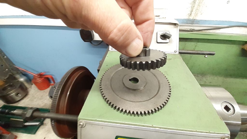
Shot showing gaps created by the spacer washers between the large gears so they don't touch and ring
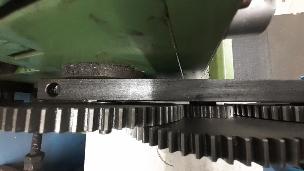
Same spacers keep gears away from Banjo
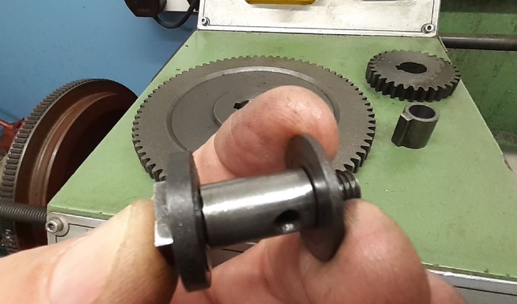
This one shows that with the washer on the 6mm spigot it bears against the studs shoulder so width for bush is constant and you WILL have room to fit the gears with "C clip" in place
Not sure why you had to ream out the 14mm holes, mine are all untouched and the bush a firm push fit so there is no wobble of gear on bush
There should also be a washer on the gearbox input inboard of the fixed keyed bush that has the shear pin through it
The two machined not pressed washers 1.5mm and 2.5mm thick, 25mm OD, 6mm ID
Setting gear positions with a strip of paper
Two images showing that sideways adjustment of banjo on it's pivot can at each extreme have the gears rubbing together or gears rubbing the banjo so set it about mid way
Lastly over riding the interlock this is what my gears run like first at 500rpm, then 1000rpm then with feed engaged. All motor noise to my ears
I have been out in the workshop, Put the washers in – The rightway round!!!
The gear wheels never fitted the shafts they were so undersized it was a joke. I drilled with a drill bit borrowed from an engineering shop that was very slightly under 14mm, then reamed to get them to fit. I even had to file 2 of the key ways.
I used the paper to set up. When done the drive forced the arm with the change wheels out of mesh & it means I have to push it up very hard & really tighten it beyond what one might expect. But I cannot see where there is any stiffness. The slide is not overly stiff on the bed,
As for noise – Still much noiser than yours, but bearable if I stick below 650 RPM above that & the arm jumps out of gear. Only leave it set up if I intend to use it otherwise I will just disengage.Mine is nearly as noisy as yours without the change wheels engaged.
I did not grease the wheels but used chainsaw oil as it is sticky & does not fly out. I also use it as a cutting fluid & it works OK & is cheap.
So I will see how it goes
But thanks for your help, You have spent too much time on it all ready but it is much appreciated
… I sometimes regret buying this lathe– as they say " the bitterness of poor quality lingers long after the thrill of low price is forgotten.
They also say 'a bad workman blames his tools'!
I like to break problems down into possible causes. Machining problems are due to the material, or the tool, or the operator, often in combination.
When things go wrong experienced machinists carefully eliminate all possible causes, including the possibility they need to learn new tricks. Is the material sticky, hard, gritty, or liable to work harden? How stiff and powerful is the machine? What balance of depth-of-cut, feed-rate, and speed works best? Is the machine adjusted correctly? If the machine has fundamental shortcomings, can they be circumvented by a workaround or skilled driving? Some problems are complicated, making it all too easy for beginners to get out of their depth and not understand what to do about it. You can guess how I know!
There's no shame in being a Learner. Self teaching is slow and painful compared with having a mentor pointing out simple mistakes as you go. Over-confidence is a sin, so beware jumping to conclusions.
Though YouTube is useful for seeing techniques in action, I find it better to start with books and magazines. A serious problem with YouTube is the huge amount of flawed material posted by unqualified persons: they unwittingly make lots of mistakes, and their advice is often untrustworthy. Another problem is inexperienced viewers drawing wrong conclusions due to not understanding the video's context. Imperfect though it is, this forum does much better because there's dialogue.
Sam's problem may be due to going a step too far. He hopes a diamond/tangential cutter will remove metal quickly before understanding his lathes limitations and the relationship between motor power and surface speed. The house is built on sand.
Actually, even if the lathe were perfect, a tangential cutter removes metal at much the same rate as any other HSS tool. It's because a certain amount of energy is required to cut a material irrespective of the cutter type: rule of thumb for HSS and mild-steel is 1HP will remove about 1 cubic inch of metal per minute. Above that HSS will soften. I suspect Sam needs a bigger lathe, not a 'quality' machine of the same size.
Pinched off Practical Machinist. The formula for Horsepower Required is:
HP = UHP X MRR
UHP = Unit HP (taken off chart)
MRR = Material Removal Rate
Some UHP numbers off chart:
Aluminum .25
Steel 1.4-2.5
Alloys 2.0-3.3
Not so obvious, is what limits removal rates. Motor power, torque, and max rpm; strength and efficiency of the drive train; cutter shape and what it's made of; coolant; desired finish; and rigidity of the machine all effect the rate. In practice, high-speed metal cutting is best left to modern industrial machines. They cost 10 to 30 times more than hobby kit.
For hobby purposes small lathes have fractional HP motors – they aren't metal munchers. General purpose hobby machines are between 400W and 2500W depending on size. It means the hobby operator has to set the machine up correctly, adapt his technique for best results, and not expect easy perfect results. Operated carefully they produce good work slowly. They are what they are.
Sam there is a cap head screw that tightens the banjo (arm) onto it's pivot, it sounds like you are unaware of this and just pushing the banjo into mesh. You also need to use the paper method for the fixed spindle gear to the first gear on the banjo. If you are doing it up then post a few photos as I may be able to spot something else not right, can't say I've ever had mine jump out even when taking 6.35mm DOC (12.7mm off dia)
As the lathe comes with the feed gears already assembled I would assume you did not need to ream these so they should still be a decent fit.
Those familiar with this type of lathe will immediately know what Sam was talking about when he said "circlip" for that don't know what is being discussed this is the item. The narrower slot fits the groove in the end of the stud, t he wider slot registers against the studs square end preventing the retaining disc from rotating.
Oh and it is also hardened, only tested with a file but it is hardened.
If cutting forces forced the gears out of mesh then either you are asking too much of the machine, or you did not clamp the banjo tightly correctly..
You are obviously new to the hobby, and rushing things without reading the instructions.
You bought the machine new, so have an Operator Manual.
Study it, and make yourself familiar with the machine, the location and function of the controls
You removed from the machine a safety feature which also carried a chart which would probably have answered some of your questions.
SLOW DOWN.
It used to take four years for a man to become a skilled turner. You will not achieve that, as a first time lathe owner, in a couple of weeks. We all started without having even seen a lathe, let alone operated one.
We ALL learn something every day
You need some face to face tuition.
I try to help newcomers to the hobby, but you are being over confident and missing the basics, which makes it difficult for anyone to help you.
You have a new machine, so wear or abuse (Other that which you have applied ) should not be an issue.
Where are you located? Maybe, someone near you will be willing to come over and help you.
Find a local model engineering club, join, and watch and listen.
If you have not got one, buy a bench grinder and learn how to grind tools, and then how to set them
Buy some of the recommended books, and study them. The answers to a lot of your questions will be in them..
Sorry to castigate you, but dashing in without knowing what you are doing, will continually make problems.
Sam there is a cap head screw that tightens the banjo (arm) onto it's pivot, it sounds like you are unaware of this and just pushing the banjo into mesh. You also need to use the paper method for the fixed spindle gear to the first gear on the banjo.
As the lathe comes with the feed gears already assembled I would assume you did not need to ream these so they should still be a decent fit.
Please give me a bit more sense than that. I am aware of the screw & i used a large allen key to tension it.
All the change wheels were in a tin box & NOT fitted. They could not have been as supplied.
Sam see my earlier edit to the post you just quoted. One simple thing to try would be to add a washer under the head of the cap head screw incase it is running out of thread length and going tight before closing the split. Failing that take the gear off the input shaft and closely watch what is happening to the part the banjo pivots on as you move the banjo incase that is loose. Might have happened when you crashed the carriage into the stop some time back
As far as I'm aware they all come with the fine feed gear train set up as has been confirmed by another poster in this forum, can't explain why yours was different.
..it's a far more convenient system for holding changewheels than having to fiddle about in the gloom with oil-covered straight-slot 2BA screws..
..pretty sure I've seen an Emco with similar fittings – was this a bit of teutonic efficiency copied over from the european ancestor of the Weiss machines?
The gears on a 1950s Raglan never needed the gear retaining set screws removing – just loosening sufficiently to slide off the gear-retaining slotted washer is all that is needed. The gears were of sufficient bore (5/8&rdquo to be easily removed without removing the set screws. Clever design, or what, back then?
Seems to me that either designs have gone backwards over the last 60 years or cheapness has taken over. As for gears that needed to be drilled and reamed to fit (should have been bored and reamed, of course)? That seems to be good example of poor chinese production, don’t you think? It is not really surprising that the gears might be more noisy if the bores were drilled out.
Are these really circlips that are used to secure the gears, or are the gears fixed in a more user-friendly way? The adjustment banjo seems to be only part of the problem. Clearly not all users are as clever as yourself. Perhaps the modern machines need to be made more fool-proof in this day and age? Like many modern items, they seem to be built for a (very) limited lifespan.
I, personally, can understand your defence of the chinese offerings. Sometimes perhaps too defensive, in my view.