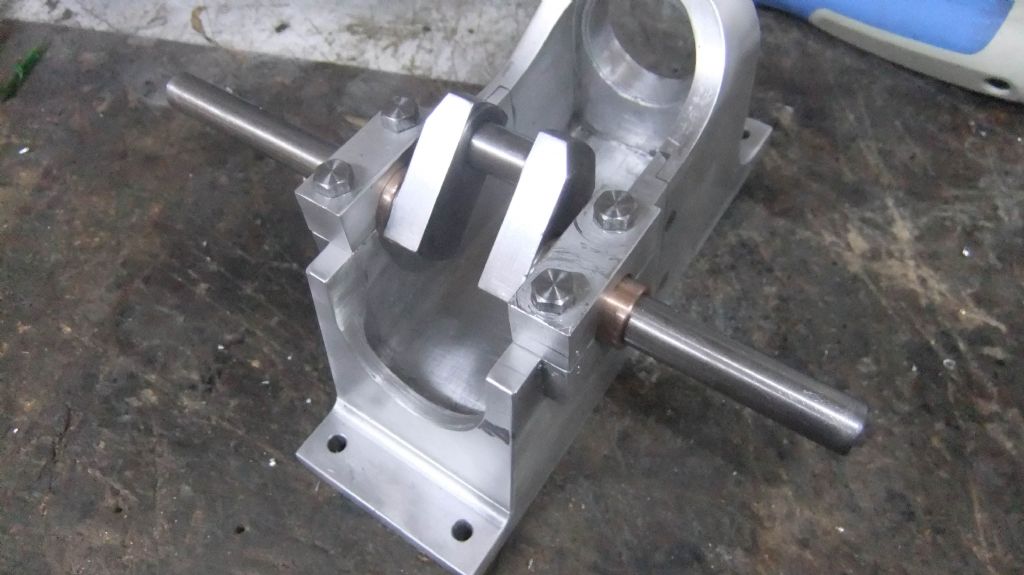
What with making the crankshaft the next part was drilling and reaming for the main bearing, as well as making the bearings which was not so bad.
Anyway this job was done without any problems but I did spend a little time setting up to do this task.
All done and fitted just a little clean up now to get rid of some marks. I do need to ream the bearings again as the caps pinch it very slightly rather this than too loose.
A simple job completed and that is to prepare the blanks for gear cutting, I need to do a little reading on the dividing head to cut the teeth.
One of them is steel and the other bronze they also need to be just right for the diameter as well as the centre hole size.
Started to set up for cutting the gears, but things needed doing first. Starting with an arbor for the gear cutter. Then discovered that my milling machine clamps were to large to hold the rotary table in the vertical position (It also acts like a dividing head) so two clamps were made luckily I could use the T nuts and the threaded rods.
Finally managed to get set up as can be seen.
And even better managed to complete the larger of the gears. Now that I have completed my first go at a gear I feel more confident to do others as and when needed
Just a couple of small parts made over the last couple of days. I did waste over an hour looking for my 1/4″ collet which seemed to disappear into thin air, workshop gremlins at work to only find it right in front of my eyes sitting on the lathe why it should be there as I last used it on the milling machine.
Anyway the two parts which enabled me to test the gears on the frame(rubbish video but you get the right idea) a bit awkward using one hand as I was steadying the camera with the other
Turned the main body but left it on the main stock as there are other things that need doing to it that require the extra material to hold it.
After the turning I made the two arms followed by cutting a couple of slots in the turned part, still need to drill two holes that is why it is still set up in the milling machine touch wood that will be tomorrows job followed by turning a couple of pins ready to silver solder the arms in the slots that will be another thing that I have never done before I am alright soft soldering.
The governor parts pile has some more parts added to it all small parts but seem to take ages to do even if they are simple still some more to make. I have not yet soldered any parts as there are a few more that need hardening so will do the soldering and hardening all at the same time weather permitting as it is raining here.
if this is going take as long as it does to make a posting you can follow my build on the Model Engine makers forum if this site improves then I may start to repost again but until then see you on the other site
I had to remake the small fuel delivery bar as I was drilling it with a cross hole and messed it up as the bit was a #76 which is quite small. Now that is all done.
Some photos of the fuel mixer with the bar which is only 1/8″ diameter so that gives an idea of the cross hole size.
The last part of the fuel mixer assembly is the elbow. Not having one, I thought I would have a go at making one which will give me the chance to do some silver soldering, as well as a very simple start to fabricating.
I started with 1/2″ brass bar and turned the ends and centre section as needed, with a piece of steel made a quick and simple mandrel which I loctited on and clamped at a 45deg angle in the mill vice and notched out before heating to cherry red and bending to form the angle. I thought this was easier than cutting it into two parts and trying to keep it lined up while I soldered it.
I filed the outer corner of the bend as it looked wrong being left with a sharp corner
The photos should help explain my method of making this.
I have made several hit and miss and other IC engines with single round Viton rings and all run OK
Only built one where a quad ring was specified and also found that difficult to get so ran it with a round one and it was OK, did also work with no ring as well.
What with other jobs, not a lot of workshop time. But I have been able to apply some paint to the main body as well as get one of the flywheels set up for machining, more on that later when there is progress.
Anyway the paint job it may not be everyone’s taste in colour. Thank you to all that gave advice on the best to use.
It has got a top clear coat which is petrol resistant.
Well after a short break from the Farm Boy what with looking after my wife after a week in hospital as well as doing the cooking and housework and trying to catch up with gardening, I have finally managed a couple of hours in the workshop even if it was only to make a collet for a 1/8″ broach to cut the keyways in the two flywheels. As well as a very quick tidy up and sorting out a new Arbor press which the wife treated me too.
I should now be back with some progress. Photo of the press, but still need to slot the collet.
Back onto the Farm Boy with the beginning of turning the flywheels, these were done on a faceplate. Only one side on both of them the outer diameter is just a little over the final size so that once fully machining of the centre and the sides I will take the diameter to final size mounting it on an Arbor.
I have managed to start on the second side of the fly wheels, bringing the diameter to 6″ and cleaning the sides. I have started to bring the centre boss down to size, as can be seen in the photos. The flywheels are cast iron and certainly make a mess when turning, my hands were black just doing these few operations as it gets everywhere as you all know.
I have now sorted out the centre boss and extended one side as they are a little short.
I have now completed the main turning on these, with only the tapered turning on one side of each to do, and the holes drilled for the fixing flange to attach.
I also managed to form the keyway on both, which I was nervous about as the broach is only 1/8″ wide, but it went a lot easier than I expected.
If I thought I was back on track with my last post, it has only taken me since then to drill and tap 6 small holes. This was due to me going down with a severe chest infection and not fit to play with machines.
Hopefully (touch wood) I am now back on track.
So nearly finished the flywheels, just need to put a taper in the centre hole which will become clearer in the operation after that
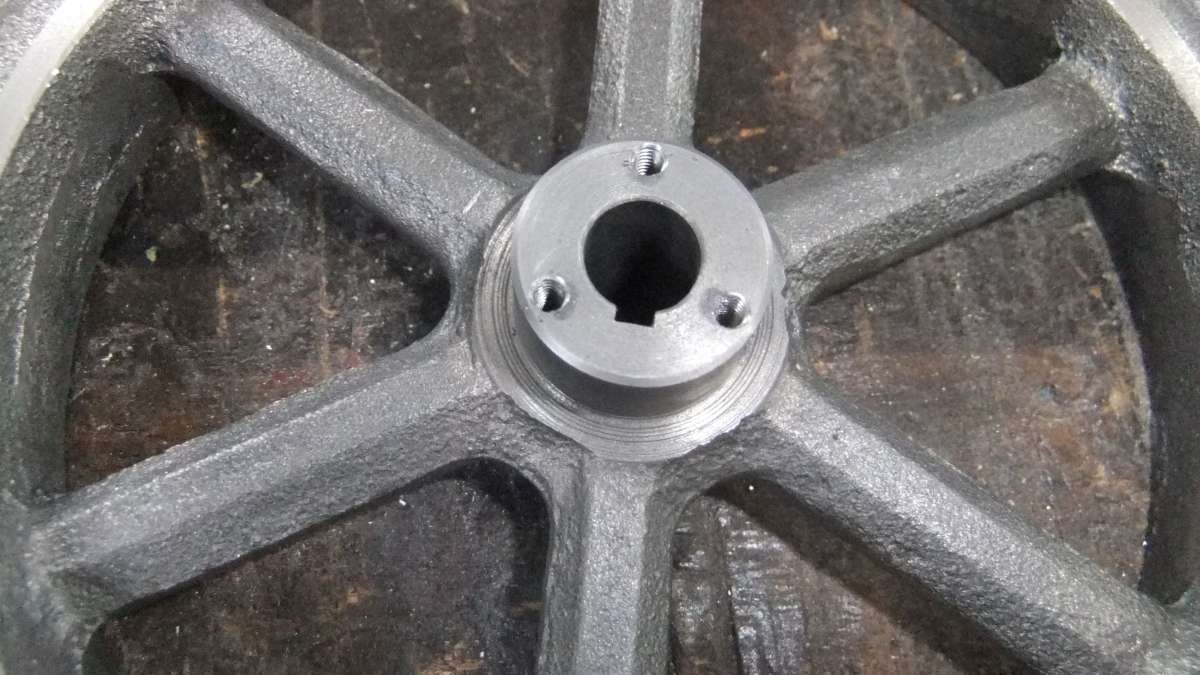
What with different things getting in the way, I finally got around to a little more work on the Farm Boy engine.
The flywheels needed a taper putting in the crankshaft hole and also a tapered fixing made to match. Going by the plans, the opening in the flywheel just cut into the three screw holes, which surprised me.
I mounted the flywheels on the faceplate and dialled them in before setting the angle and turning these. Both flywheels were done before turning the matching locking fixings. This meant that the cross slide was already set and both tapers matched.
Still need to drill the fixing holes and also two threaded holes to use if they need extracting from the flywheel in the future as well as a slot.