Failed to get this digital clock kit working :(

Advert

Failed to get this digital clock kit working :(

Home Forums Clocks and Scientific Instruments Failed to get this digital clock kit working :(

Viewing 25 posts - 1 through 25 (of 57 total)
  • Author
    Posts
  • #543887
    Michael Gilligan
    Participant
      @michaelgilligan61133

      I decided it was time for some soldering practice … so I dug-out a little digital clock kit that I bought a couple of years ago.

      My soldering is not as good as it used to be, but; looking at it under the stereo microscope I’m reasonably satisfied that the joints are O.K.

      Problem is … it doesn’t work, and I have no idea how to fault-find the circuit: Constructionally, it’s very simple, but there is no description of how it works.

      The big IC is actually an Atmel AT89C2051 microcontroller, although the board is labelled for STC12C2052 dont know … are they interchangeable ?

      There is no information, but I had assumed it to be supplied pre-programmed.

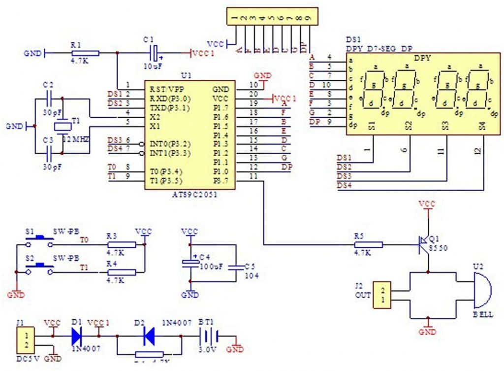
      The same kit appears to be listed on Amazon and Alibaba, both of which show this [inaccurate because J2 is not on the board] diagram:

      9d7f9cb4-8312-4549-9107-db85469e3efb.jpeg

      .

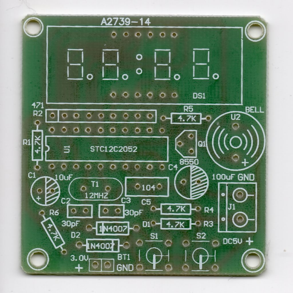
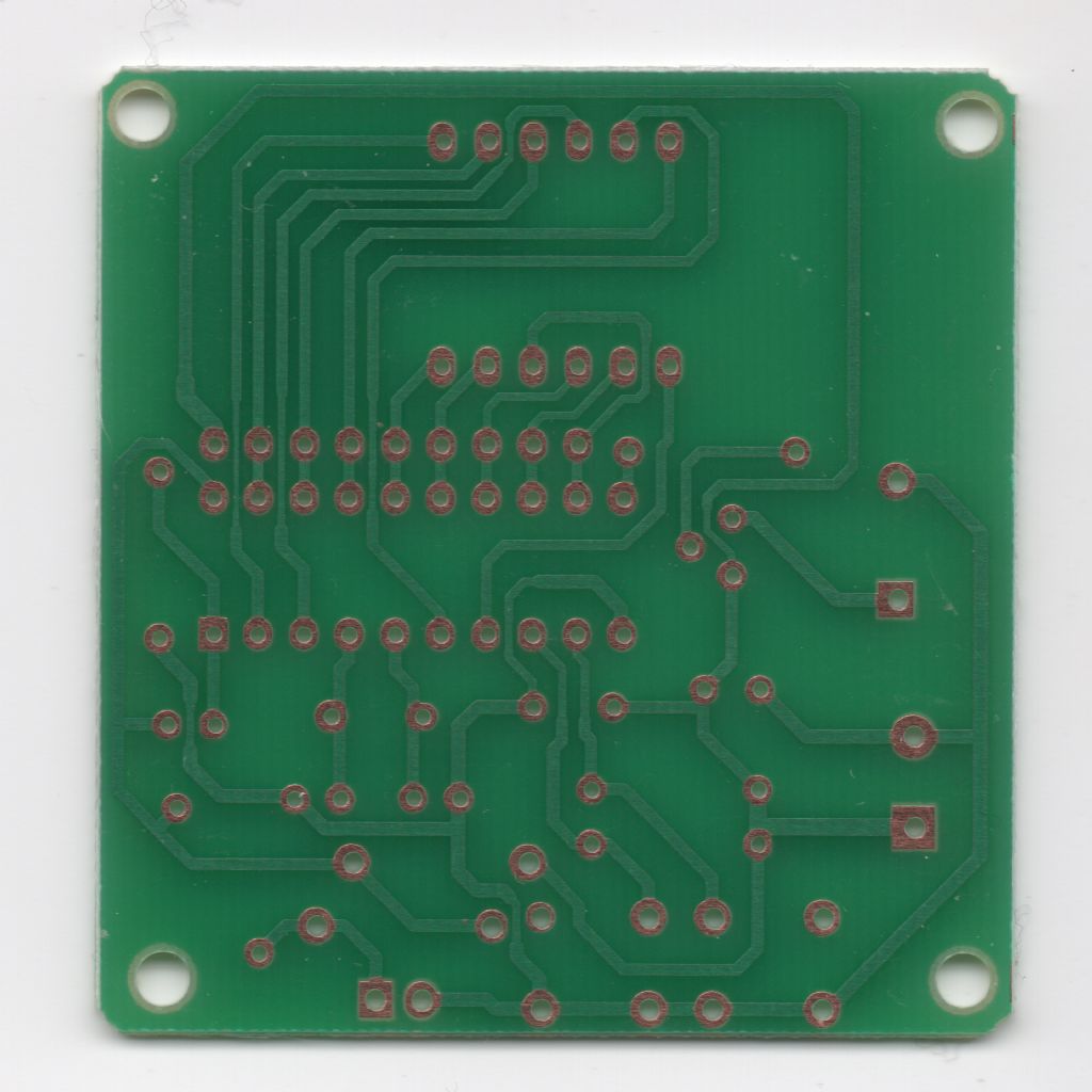
      Here are scans of the circuit board [with the track-side horizontally flipped for convenience]

      .clock_pcb_a.jpg

      .

      clock_pcb_bf.jpg

      .

      Does anyone recognise it ?

      … or have any idea where I should start fault-finding

      … or any useful suggestions as to what I might do with salvageable parts ?

      MichaelG.

      Advert
      #3925
      Michael Gilligan
      Participant
        @michaelgilligan61133
        #543900
        Frances IoM
        Participant
          @francesiom58905

          I guess you didn’t use a socket for the microprocessor thus depriving you of many simple tests on the wiring and the display. If you did then you can obvious check all the connections and by judicious use of jumpers test out the display

          #543908
          Joseph Noci 1
          Participant
            @josephnoci1

            Michael,

            Bit of a poor design inthe way it drives the led display, Michael. The processor sets up a 7 seg display code on the the lines A to G and then pulls one of the scan lines DS1 thru DS4 low. So, to show the figure 8 on display 1 ( left digits), lines A-G will be set HI . Line DS1 is then pulled low and all the segment LEDs will glow.. If DS2 is also pulled low, Display digit two will glow, etc.

            What makes the design poor is that when powered from 5V, the 7seg leds will have about 4 to 4.5V across them, with a large current flow, all sourced by the processor output pins – not good for the processor at all!

            I see when running from battery the supply V=3V, much better!

            If the processor is not working , it will not be scanning the A-G lines at all. I presume you do not have an oscilloscope? If you do, check the A-G and DS1-DS4 lines – there should be pulse trains on them.

            If no 'scope, just short one of the DS lines to ground – if the processor is scanning the A-G lines, a 7seg display will remain on during the short – this 'should' not damage the processor, as the DSx outputs are normally pulsed low and then go hi-impedance to not activate that display – They may however drive the output HI rather than hi impedance, so..

            A neater way is to take a red led ( lower on voltage) and connect the cathode to ground, and the anode to each A-G line in turn – you should see it glow if the lines are being driven.

            If not, there are two probable causes – The processor is not programmed, or the oscillator is not..To see if it is oscillating, first check carefully around the crystal, the two capacitors C2 and C3 ( are they really 30pf – can you see any markings?)

            If visual is good, do you have a short wave radio? Set the dial to around 12MHz, and bring a wire from its antenna socket and touch the crystal metal can – tune around the 12MHz range till you detect the frequency – it should be very strong…

            Let me know

            #543914
            Mike Poole
            Participant
              @mikepoole82104

              It’s funny that I have exactly the same kit and mine doesn’t work either, I have another one to assemble so I wonder if that will be 3 out of 3 that don’t work? I will post when I have built it.

              Mike

              #543916
              SillyOldDuffer
              Moderator
                @sillyoldduffer

                The 2051 and 2052 appear to be pin compatible and both support the same instructions. The 2052 looks to be a bit faster and have a couple of extra timers, but those features are unlikely to be needed on a simple digital clock.

                The circuit is very simple; most of the clock is implemented by a program running on the chip. The chip should be pre-programmed : unlikely it went wrong, but possible.

                Reading the reviews I see a few people complain about board quality – tracks lifting off with heat, and broken tracks that had to be bridged. Check the tracks carefully with the microscope and for continuity with a multimeter, or – much better an oscilloscope, see below.

                Apart from Frances' advice# about maybe testing the display by jumpering, I think debugging needs an oscilloscope. If you've got one, should be possible to see:

                • 12MHz continuously on both crystal pins, proving the oscillator is running. Or listen to it on a Short Wave receiver (another expensive toy you deserve!)
                • 5V between Vcc and Gnd. If the chip has no power, nothing will work because the display is powered by the chip.
                • Activity between Gnd and all the other pins, square waves changing from 0 to +5V. The display is multiplexed by pulling DS1, DS2, DS3 and DS4 to ground, or by putting 5V on them, in sequence, above eye flicker frequency. Which way round depends on whether the display is common cathode or common anode. The segments draw digits by putting power on A,B,C.D,E,F & G selectively. Which segments are active depends on the digit being displayed. An '8' does all of them, while '1' only lights up b and c. The final digit of HH:MM will change fastest.
                • T0 and T1 should both be high until a button is pressed. If the chip has power and the oscillator is running, either of these switches stuck down at zero volts might cause the program to hang.
                • RST should pulse once up to 5V when the clock is powered on and almost instantly subside to zero. Normally it should be zero. The pulse is important because it restarts the computer after the power supply has stabilised. If RST isn't pulsed the chip won't start the clock program correctly at the beginning and it probably won't work at all. The RST pin has a 10uF and 4k7 resistor connected which is correct for a go-faster 2052, but may not be right for a 2051. The 2051 example circuit I found simply connects 10nF between Vcc and RST : might be worth trying if all else fails.

                Dave

                # Joe posted while I was typing.

                Edited By SillyOldDuffer on 08/05/2021 16:54:41

                #543924
                Michael Gilligan
                Participant
                  @michaelgilligan61133
                  Posted by Frances IoM on 08/05/2021 15:17:36:
                  I guess you didn't use a socket for the microprocessor thus depriving you of many simple tests on the wiring and the display. If you did then you can obvious check all the connections and by judicious use of jumpers test out the display

                  .

                  Why would you guess that, Frances ?

                  The kit came with a socket, and yes, I used it.

                  MichaelG.

                  #543926
                  Frances IoM
                  Participant
                    @francesiom58905

                    It was an assumption as you didn’t comment on it – thus I now assume that as you have checked out that all connections are correct and the display works then what remains is the micro processor (or possibly the Xtal oscillator) – without a scope this is difficult – however if you have an audio jack then there are pseudo-scope programs (eg Audacity) that can display the signal on this jack – they should be fast enough to at least check the display multiplexing.

                    Edited By Frances IoM on 08/05/2021 18:01:33

                    #543928
                    Michael Gilligan
                    Participant
                      @michaelgilligan61133
                      Posted by Joseph Noci 1 on 08/05/2021 15:57:15:

                      Michael,

                      Bit of a poor design inthe way it drives the led display, Michael.

                      […]

                      Let me know

                      .

                      Yes, I do have an oscilloscope, Joe … ‘though it’s currently in storage

                      No, I don’t have a short wave radio

                      Yes, the capacitors are marked 30

                      Thanks for the comment about voltage … I tried it with 5V from a USB ‘power bank’ but can happily use the 3V input.

                      Absolutely nothing lit-up, but there was a very brief squeak from the sounder.

                      I will find a way to check the oscillator and the display … but the microprocessor and its programming [or lack-of] are a complete mystery.

                      MichaelG.

                      #543930
                      Michael Gilligan
                      Participant
                        @michaelgilligan61133
                        Posted by Mike Poole on 08/05/2021 16:46:48:

                        It’s funny that I have exactly the same kit and mine doesn’t work either, I have another one to assemble so I wonder if that will be 3 out of 3 that don’t work? I will post when I have built it.

                        Mike

                        .

                        Thanks, Mike … I have another one too; but thought I would seek advice, in case the components are more useful than the kit.

                        MichaelG.

                        #543931
                        Michael Gilligan
                        Participant
                          @michaelgilligan61133
                          Posted by Frances IoM on 08/05/2021 18:00:40:
                          It was an assumption as you didn't comment on it – thus I now assume that as you have checked out that all connections are correct and the display works then what remains is the micro processor (or possibly the Xtal oscillator) – without a scope this is difficult – however if you have an audio jack then there are pseudo-scope programs (eg Audacity) that can display the signal on this jack – they should be fast enough to at least check the display multiplexing.

                          .

                          I have checked the connections to the best of my ability … but no, the display has never been seen to work.

                          … I will report back when/if I discover anything.

                          MichaelG.

                          #543935
                          Michael Gilligan
                          Participant
                            @michaelgilligan61133
                            Posted by SillyOldDuffer on 08/05/2021 16:52:23:

                            The 2051 and 2052 appear to be pin compatible and both support the same instructions.

                            […]

                            Dave

                            # Joe posted while I was typing.

                            .

                            Thanks to you also, Dave … I think, I’ve thanked everyone now

                            As per my other replies : I will report back if I get a glimmer of life out of it [aside from that brief bat-squeak]

                            MichaelG.

                            #543940
                            Nigel Taylor 2
                            Participant
                              @nigeltaylor2

                              I have built two of these kits.

                              Neither worked…

                              #543941
                              Frances IoM
                              Participant
                                @francesiom58905

                                with the uP removed jumpering a 1k resistor from vc1 to one of the display pins and jumpering one of the multiplex pins to 0V should light up something on the display which, maybe wrongly, I assume is soldered in position and oriented correctly ?
                                I this fails then remove the display, insert the up and if you can run a program like audacity (or even better one of the programs on a Raspberry Pi – surely everybody has one of these by now) you should be able to check out the uP

                                Edited By Frances IoM on 08/05/2021 18:35:39

                                #543954
                                Michael Gilligan
                                Participant
                                  @michaelgilligan61133
                                  Posted by Frances IoM on 08/05/2021 18:34:59:
                                  with the uP removed jumpering a 1k resistor from vc1 to one of the display pins and jumpering one of the multiplex pins to 0V should light up something on the display which, maybe wrongly, I assume is soldered in position and oriented correctly ?
                                  I this fails then remove the display, insert the up and if you can run a program like audacity (or even better one of the programs on a Raspberry Pi – surely everybody has one of these by now) you should be able to check out the uP

                                  .

                                  Thanks, Frances … Yes, the display is soldered in; although I didn’t fit it flush to the board, but raised so the face is just above the height of the sounder. It is orientated as per the graphic on the board.

                                  Sorry, but … As I don’t actually know what program is supposed to be on the microprocessor, I’m struggling to understand how I could check it.

                                  MichaelG.

                                  #543955
                                  Frances IoM
                                  Participant
                                    @francesiom58905

                                    I’m assuming that one possible error is the loading of the display on the uP – the uP should go through its program without the display and the multiplexing pins should be low enough frequency for Audacity to display it.

                                    I assume that the uP is a one-time programmable chip (maybe SOD in possession of a data sheet could confirm) – many of these have a mechanism to prevent readout of the program

                                    #543958
                                    Michael Gilligan
                                    Participant
                                      @michaelgilligan61133

                                      Atmel datasheet [19 pages]: **LINK**

                                      https://ww1.microchip.com/downloads/en/DeviceDoc/doc0368.pdf

                                      The STC one is also available, but runs to 360 pages … the vast majority of which are beyond me.

                                      MichaelG.

                                      .

                                      Edit: being (a) from Amazon UK, and (b) currently unavailable … I trust that it’s permissible to post this link to what appears to be an identical kit:

                                      https://www.amazon.co.uk/Universal-Solder-CANADUINO-Digital-Clock-Countdown/dp/B0764WFNC7


                                      Edited By Michael Gilligan on 08/05/2021 19:48:53

                                      #543979
                                      Michael Gilligan
                                      Participant
                                        @michaelgilligan61133

                                        O.K. … This might turn out to be embarrassing blush

                                        I’ve just realised that I paid no attention to which way round I was inserting R2

                                        This is a resistor array [8 resistors and 9 pins] and the one for the one in the other kit is clearly marked

                                        • A471J

                                        That dot, I now realise, should be at the left side of the board.

                                        There is a 50:50 chance that it’s reversed.

                                        R2 is now hiding in the narrow slot between the U1 socket and the DS1 display … so I will need to check with a meter. … A little job for tomorrow morning !

                                        MichaelG.

                                        .

                                        Edit: nicely illustrated here: 

                                        http://darcy.rsgc.on.ca/ACES/TEL3M/ResistorNetwork.html

                                        Edited By Michael Gilligan on 08/05/2021 22:37:39

                                        #543996
                                        Joseph Noci 1
                                        Participant
                                          @josephnoci1
                                          Posted by Michael Gilligan on 08/05/2021 22:29:52:

                                          That dot, I now realise, should be at the left side of the board.

                                          There is a 50:50 chance that it’s reversed.

                                          That will make a difference, but reversing the array only makes the segments glow at half brightness, and the decimal point will be messed – so it should still have shown something…You did check pin 1 of the processor..(Sorry Michael…

                                          I do think you should try find a way to see if the oscillator is running at all..Borrow the neighbour's SW radio for 10 minutes.

                                          Joe

                                          #544011
                                          SillyOldDuffer
                                          Moderator
                                            @sillyoldduffer
                                            Posted by Frances IoM on 08/05/2021 19:16:28:

                                            I assume that the uP is a one-time programmable chip (maybe SOD in possession of a data sheet could confirm) – many of these have a mechanism to prevent readout of the program

                                            I don't think the microprocessor is one-time only, so it should be possible to read it back unless the 'Program Memory Lock Bits' have been set by the vendor: one prevents write, another prevents read as well. (The chup can still be reprogrammed but only by erasing the flash memory first.)

                                            Then the program would have to disassembled and studied to confirm it made sense!

                                            Deep waters and and more work than I would care to do – apart from the other complications I'm not familiar with the 8051 instruction set and would have to learn it from scratch!

                                            The chip can be programmed with an Arduino as described in this instructable, with either the ArduinioISP built-in example, write only, or using the avrdude utility. avrdude can read and write so in principle the binary program could be extracted with a command something like:

                                            avrdude -C avrdude.conf -v -v -v -v -p AT89C2051 -c stk500 
                                            -U flash:r:"c:/extraction.hex":r -P\.COM2 -b57600

                                            I don't think it's worth the effort! And definitely not until all possibility of hardware error has been eliminated.

                                            Michael asked about reusing the components. Programming an Arduino Nano to replace the 2051 chip wouldn't be difficult. A big advantage of the Arduino platform is it hides almost all the complicated shenanigans needed to compile, install and test simple programs. Old-school programming of chips of the 2051 generation may require comprehensive understanding of hoards of tricky details, dunno. Though I'm certain there's a C compiler, I'd have to find it and get it working – unknown territory. However, even if the 2051 is easy to work with, I'd stick with the Arduino simply because there's masses of up-to-date help and I already understand it adequately.

                                            Dave

                                            #544024
                                            Stuart Smith 5
                                            Participant
                                              @stuartsmith5

                                              Michael

                                              After checking that all the components are installed the correct way round.

                                              I would suggest removing the uP chip and power up the board from a 5volt supply.

                                              Check that the supply voltages around the board are correct.

                                              It will be possible then to test the buzzer and display by using jumpers to simulate what the uP should do.

                                              The other thing that occurs to me if all this is OK is do you need to start the clock by pressing the 2 buttons in a particular order?

                                              Stuart

                                              #544026
                                              Joseph Noci 1
                                              Participant
                                                @josephnoci1

                                                It is reprogrammable FLASH chip – I am very familiar with it, extended Intel 8051 type device – did MANY projects with most of the 8051 variants , in assembler and C.. I have all the compliers and assemblers too…And the 'big advantage of the arduino platform' is no less complicated than any other method, until you know how…

                                                But all that is moot, since unless someone can do it for Michael, I am sure he is not interested in getting down low with the code!

                                                #544042
                                                Michael Gilligan
                                                Participant
                                                  @michaelgilligan61133
                                                  Posted by Joseph Noci 1 on 09/05/2021 07:29:03:

                                                  Posted by Michael Gilligan on 08/05/2021 22:29:52:

                                                  That dot, I now realise, should be at the left side of the board.

                                                  There is a 50:50 chance that it’s reversed.

                                                  That will make a difference, but reversing the array only makes the segments glow at half brightness, and the decimal point will be messed – so it should still have shown something…You did check pin 1 of the processor..(Sorry Michael…

                                                  I do think you should try find a way to see if the oscillator is running at all..Borrow the neighbour's SW radio for 10 minutes.

                                                  Joe

                                                  .

                                                  Thanks, Joe … I have an update :

                                                  1. I rigged some better lighting on the stereo microscope, and have confirmed that R2 is inserted the wrong way round.
                                                  2. I have confirmed that both the processor and its socket are correctly orientated.
                                                  3. I have confirmed that all solder joints are ‘sound’ and there are no accidental bridges.
                                                  4. I have confirmed that pin 10 of the processor is at Gnd, and pin 20 at VCC 1 [VCC minus the diode forward voltage drop]
                                                  5. and I have dug out my ‘Timer Counter’ and checked the oscillator, which is running at 12000.3KHz
                                                  6. There is still nothing on the display

                                                  Despite your previous reassurance; is there any chance that the mis-orientation of R2 could be completely blanking the display ? … Could it be a ‘feature’ of the [totally undocumented program] ?

                                                  Please don’t waste too much of your time on a silly little project that cost less than £1.50 though !!

                                                  MichaelG.

                                                  #544071
                                                  Joseph Noci 1
                                                  Participant
                                                    @josephnoci1

                                                    Thanks, Joe … I have an update :

                                                    1. I rigged some better lighting on the stereo microscope, and have confirmed that R2 is inserted the wrong way round
                                                    2. and I have dug out my ‘Timer Counter’ and checked the oscillator, which is running at 12000.3KHz

                                                    That's Good!

                                                    1. There is still nothing on the display

                                                    That's Bad..

                                                    Despite your previous reassurance; is there any chance that the mis-orientation of R2 could be completely blanking the display ? … Could it be a ‘feature’ of the [totally undocumented program] ?

                                                    Please don’t waste too much of your time on a silly little project that cost less than £1.50 though !!

                                                    MichaelG.

                                                    Doubt that R2 orientation is seen by the processor at all..

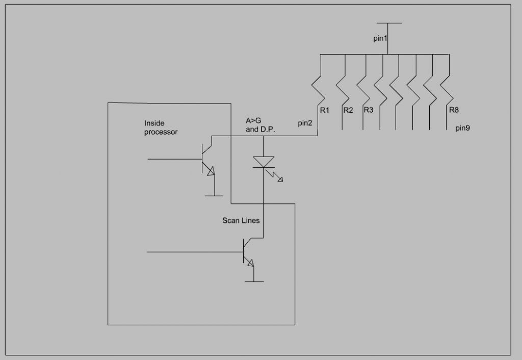
                                                    here is a crude representation of whats going on –

                                                    The processor drives open collector ( probably FETs, so open drain, but irrelevant here) transistor as shown. eight drive the A-G and D.P. segments of the displays.

                                                    4 drive the scan lines DS1-4

                                                    having looked more carefully at your schematic there is a qick test to see if the segment glow at all..will explain shortly.

                                                    So, assume VCC at pin 1 of the resistor network, ie, assume the network is inserted correctly..

                                                    Then current will flow down R1 (diagram below) through the 7 segment LED, IF the scan line transistor is on.

                                                    So, to turn on Segment 1 of display 1 ( say), as below, the A-G line transistor ( top one) must be OFF, and the scan line transistor ( bottom one) must be ON.

                                                    to turn a segment OFF, the processor will drive the top transistor ON, which pulls the the LED/R2 network pin to GND, so no current available to flow through the LED, so no glow.

                                                    Now, if you connected VCC to pin 9 instead of pin 1, then current still flows down R1, through the segment LED and the bottom transistor, BUT, it gets there via R8. Since R1 thru R8 are equal values ( 470ohm), half the current now will flow through the led, so half as bright. No other effects at all..

                                                    Now the test –

                                                    Remove the processor from the socket, power the board, and with a wire jumper, short one of the DS lines to GND. That should light up ALL the segment of one of the digits. Repeat for the others. You van see how that works – current can flow through all the segments since the top transistor is OFF ( missing), so shorting the DS1-4 line to GND provides the current flow path.

                                                    If NO segments glow, the display is faulty, or as I have had before, its a common anode instead of common cathode device…

                                                    clock.jpg

                                                    #544083
                                                    SillyOldDuffer
                                                    Moderator
                                                      @sillyoldduffer

                                                      Have you checked S1 and S2 are correctly inserted? If those switches are inserted 90° out, the switch inside is bypassed, and the circuit is permanently ON.

                                                      The operating instructions explain the program goes into menu mode by a detecting a long press on S1. If S1 is stuck in a permanent long press due to the component being physically rotated, the computer may be waiting for it to be released. As the long press never ends because the switch is shorted, could well be the program doesn't get to move on to a stage where something is displayed.

                                                      T0 should be +5 when unpressed and 0V when pressed. If T0 or T1 is permanently 0V, suspect the switches.

                                                      Dave

                                                    Viewing 25 posts - 1 through 25 (of 57 total)
                                                    • Please log in to reply to this topic. Registering is free and easy using the links on the menu at the top of this page.

                                                    Advert

                                                    Latest Replies

                                                    Viewing 25 topics - 1 through 25 (of 25 total)
                                                    Viewing 25 topics - 1 through 25 (of 25 total)

                                                    View full reply list.

                                                    Advert

                                                    Newsletter Sign-up