Face mill size

Advert

Face mill size

Home Forums Workshop Tools and Tooling Face mill size

Viewing 16 posts - 26 through 41 (of 41 total)
  • Author
    Posts
  • #623250
    JasonB
    Moderator
      @jasonb

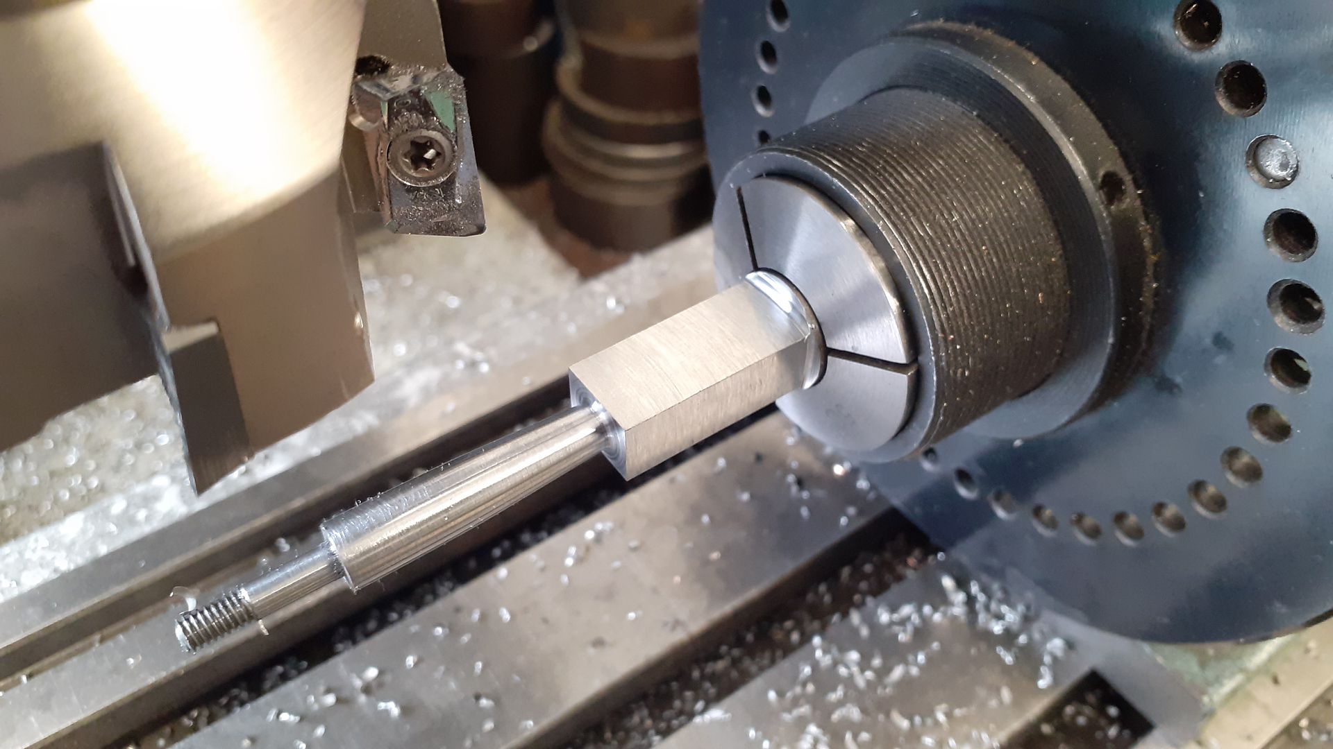
      Don't even have to keep the facemills for large flat areas, squared off this bit of 22mm EN1A at the weekend to 12 x 9 far faster than I could with a milling cutter that would have needed a couple of passes to cover the area and likely left witness marks of each pass compared to the 63mm 5 insert head with non ferrous inserts used on the X3.

      The 0.8mm corner radius of the inserts also helps with getting a nice finish that a standard milling cutters square corners don't. So that's another point in favour of the insert heads.

      Edited By JasonB on 01/12/2022 07:30:35

      Advert
      #623266
      Anonymous
        Posted by Martin Shaw 1 on 30/11/2022 22:31:52:

        …frankly if all a Bridgeport can handle is a 50mm face mill then somethings wrong.

        Not if you approach it from a proper engineering perspective and look at the numbers. My 50mm face mill has 5 inserts, at a chip load of 4 thou that is 20 thou per rev. I normally run at 800rpm, giving a feedrate of 16"/min. With that feedrate, a cut 2" wide and 0.04" deep the volume is 1.28 inches cubed per minute. In steel that would require about 1.3hp.

        My Bridgeport has an early varispeed head with a 1.5hp motor. Allowing for some loss in the varispeed drive that ties in well with the horsepower requirements. If I push it further the motor stalls. Same for the lathe (3hp); if I push beyond about 2.8 cubic inches per minute the motor stalls. So while the 1 hp per cubic inch in low carbon steel is a rule of thumb it is a good one.

        Andrew

        #623274
        Martin Shaw 1
        Participant
          @martinshaw1

          Andrew

          I posted my statement before I had the helpful info from Jelly about the power available in Bridgeport machines. Now I know better I see where your coming from and how little I know, thank you. However compare that with Jason's posts which seem at least contradictory with yours and others stance, you will appreciate the difficulty of knowing whose right.

          I have just had an email that tells me deliveries are going to be late this afternoon so probably no workshop time today.

          Martin

          #623278
          JasonB
          Moderator
            @jasonb

            I would not say my posts contradict the others it is just that the hobby benchtop mills need a different approach of lighter cuts with the spindle at the high end of what the inserts can take and helped more if the sharper non ferrous inserts are used

            Andrew mentions 4thou chip load which is approx 0.1mm, (jelly mentions 0.48mm)I have said we need to be more in the region of 0.01 to 0.02mm so that is 10 to 20 % of Andrews load which equates quite well with a wattage that may come down to 200 (1/4HP) or so when running the electronic variable speed spindle at a similar rpm. And that is without throwing in the rigidity issue or suppliers that rate the motor by input.

            Edited By JasonB on 01/12/2022 13:07:08

            #623285
            Jelly
            Participant
              @jelly

              Absolutely Jason, it's very much about picking your poison:

              • If you reduce chip load then the inserts suffer increased wear and reduced life (although using sharper inserts with smaller tip radii will help mitigate this), and is particularly bad in alloy and stainless steels.
              • If you reduce D.O.C. to maintain "optimal" chip load, you're maximising the potential damage if you do stall out the cutter, and you can run into similar problems as with chip load, but coming the other way (your D.O.C. is less than the tip/edge radius and results in uneven or excessive wear).
              • If you reduce the width of the cutting path, then you lose the advantages you were looking for by using a big face mill in the first place.
              • If you switch out the carbide face mill for a HSS shell mill, you can reduce the rotational speed (and thus the MRR) to bring the power requirements for "optimal" conditions down to something your machine can handle; but the whole job goes slower, because of the lower Material Removal Rate.

              IME a combination of making compromises from the "perfect" conditions which are spread across multiple different areas will give the best overall results.

              ​​

              I have lots of experience with larger mills and turret mills, but not much with the little "hobby" mills (I would call my Harrison a hobby mill, but it's got a lot more mass and "beans" than a Sieg so it's a matter of perspective), so it's hard for me to argue with Jason's suggestion that dropping chip load first is the optimal approach…

              My personal experience is that face with lots of parts to do or a critical part to machine, if i don't have a "recipe" ready to go and need to fine tune, then I will usually do this empirically by a combination of sound (does the cut sound even), surface finish (am I getting tearing or vibration) and ammeter (is the motor drawing close to it's full load amps).

              In that context Jason's approach offers a good starting point to work from.


              Getting maximal productivity is less critical in hobby work than in a production or operational environment where time is always in short supply, but it's still satisfying, and sometimes necessary if you have ambitious projects.

              Edited By Jelly on 01/12/2022 14:42:47

              #623286
              SillyOldDuffer
              Moderator
                @sillyoldduffer

                I'm not seeing contradiction in the answers, more the pieces of a jigsaw puzzle coming slowly together.

                The factors are:

                1. Motor Power. As a rule of thumb one HP removes 1 cubic inch of mild-steel per minute irrespective of the number of cutting edges in play. You can't cut metal faster than your motor can manage.
                2. Rigidity. The machine has to absorb cutting forces without flexing or vibrating. Not all machines are equal: a heavily built industrial machine can take more force than a light hobby machine. Adding a giant motor to a lathe or mill is usually counter-productive.
                3. The amount of time a cutter is actually cutting during each rotation.

                A fly-cutter only cuts on 180° degrees of each turn, therefore the motor is only loaded 50% per of the time. This is good on a hobby machine, because it gives the motor time to cool off and regain momentum. On the downside, the 50% duty cycle causes vibration, worse because the cutter is unbalanced, and metal is removed at half the possible maximum, which is a huge sin in production work. Nonetheless, a fly-cutter in good condition used within its limitations, essentially light cuts, eventually gets the job done and with a good finish.

                A face cutter is much better balanced than a fly-cutter, and so can take deep cuts, remembering deep cuts are often necessary to get a proper finish from carbide. Face cutters also have more cutting edges, the effect of which is to load the motor throughout each turn; a 5-toothed cutter engages every 72° increasing the rate at which a machine can remove metal, provided the motor can cope! Fast metal removal is dubious on a hobby machine because it risks overheating the motor, damaging the drive train, and over-stressing the electronics.

                My view is it's impossible to get the best out of a big face cutter on a small hobby mill. Instead the operator has to back-off, perhaps to the point that the job could be done just as well with a fly-cutter! However many owners report their moderately powerful and rigid hobby mill gets reasonable performance out of a small face mill, and they're worth buying. It's not that bigger ones fail embarrassingly, the problem is they only manage light cuts on small mills, and might damage it, in which case buying an oversized cutter is a waste of money. Their extra diameter and teeth don't add value unless the mill is hefty enough to drive them.

                Dave

                #623290
                Martin Shaw 1
                Participant
                  @martinshaw1

                  Well my simple question has produced yes, no, and maybe as answers which strikes me as contradictory. I do however respect the effort folks have gone to to give me the best possible understanding of what I'm wanting to do and how it may or may not work. If nothing else I now know better than I did. I'll give it a go and it will either go well or not. If it does I've won a watch, if not well I've bought an 80mm cutter for a yet as unknown reason.

                  Thanks you all

                  Martin

                  #623303
                  JasonB
                  Moderator
                    @jasonb

                    Well I got time to have a little play

                    ARC SX2.7 mill running at 750rpm

                    ARC 80mm six insert shell/face mill & R8 Arbor

                    ARC APTK inserts for non ferrous, used not new.

                    Material GR17 (Grade 250) cast iron 71.5mm width cut

                    Although there is no cutting data published for this type of insert used on iron similar shaped ones have figures of 120-220m/min cutting speed, the combination above is towards the top end of that at 188m/min.

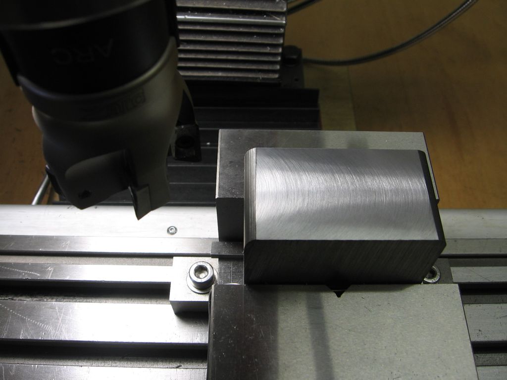
                    With the material mounted skin side up I took two cuts of 0.5mm height, the first removed the high side so did not really give a full width cut but machine was quite happy with me feeding at 80mm/min which equates to a chip load of 0.018mm/tooth. Second similar cut did just get upto full width and machine was still quite happy with that cut. The curls of cast iron swarf show that the inserts are cutting and not rubbing

                    I then took a 1mm high cut and the machine did start to sound as though it was working so I did not push the feed over 60mm/min which equates to a chip load of 0.013mm/tooth. Finish is good considering I'm having to feed one handed as phone is in the other hand which is never going to be the smoothest option.

                    For those that want to know the MRR then the 0.5mm cuts were taking 0.17cu in/min and the 1.0mm cut worked out at 0.26cu in/min.

                    So there you have something to go by as a starting point Martin, if it were me I would stick around the 0.5mm depth, possibly feeding a bit faster say 100mm/min or stay with the 80mm and try a little deeper at 0.75mm. I don't think I would be happy running at the 1mm DOC on that wide a workpiece for an extended time.

                    With no engineering background I give my opinions based on using benchtop machines so don't base things on what has traditionally been done with larger more solid machines equiped with mechanical speed control rather than variable electronic control and suggest what I have found to actually work in practice for me.

                    #623308
                    JasonB
                    Moderator
                      @jasonb

                      Now it has been shown that the mill can cope with the 80mm face mill on 70mm width of iron it's interesting to compart the various methods that could be use don the mill.

                      Based on a 70mm x 70mm workpiece and say 1mm to come off the face.

                      1 Face mill

                      With a swing of 80mm the the workpiece will need to move just under 90mm to completely cut the face, If we go with the 80mm/min feed and two cuts of 0.5mm depth total cutting time will be approx 2mins 15seconds

                      2. Flycutter

                      A counterbalanced 63mm dia flycutter with HSS bit set to swing an 80mm dia with a cutting speed of 25m/min would need to be running at a lowly 100rpm. from test cuts with this sort of setup the SX2.7 can cope with a DOC of 0.33mm when combined with a feed of 25mm/min. The three passes required would give a cutting time of 10mins 45secs

                      3. Milling cutter

                      Lets say a 12mm cutter with 10mm stepover so that will be 7 passes to cover the workpiece, they will be shorter at approx 80mm and can be done at the full 1mm depth. Based on the same 25mm/min cutting speed and lets say 0.075mm/tooth chip load and a 4 flute cutter if my maths is right that would give a cutting time of 3mins 33secs.

                      If returning the work to start the next cut were taken into account the facemill with it's two passes would have an even faster overall time and the difference between flycutter and milling cutter would be less as the milling cutter needs winding back twice as much as the flycutter.

                      Flycutter is likely to be the cheapest option as you can get a lot of sharpenings out of a bit of HSS. Milling cutter will get all the wear at the end and waste the rest of the flutes unless you have a means to sharpen. Facemill probably the highest cost for initial setup (Assuming half decent inserts) but longest time between needing new/sharpened cutting edges. If that were an iron casting rather than CI bar then the inserts will also cope a lot better than HSS which could be blunted in an instant if it hits a badly chilled area or other such hidden nasties.

                      Edited By JasonB on 01/12/2022 19:21:50

                      #623312
                      Michael Gilligan
                      Participant
                        @michaelgilligan61133

                        Nice demo, Jason yes

                        … should be a useful point of reference for future enquiries.

                        MichaelG.

                        #623320
                        Martin Shaw 1
                        Participant
                          @martinshaw1

                          Jason

                          I'm immensely grateful to you for having taken the time and trouble to try this all out, make a demo video and generally all but do it for me. The thread had led me to doubt whether I was doing the right thing however you have proved it will work, I just need to follow your guidance. I have received all the bits from ARC so it's down to me now.

                          Thanks

                          Martin

                          #623386
                          Martin Shaw 1
                          Participant
                            @martinshaw1

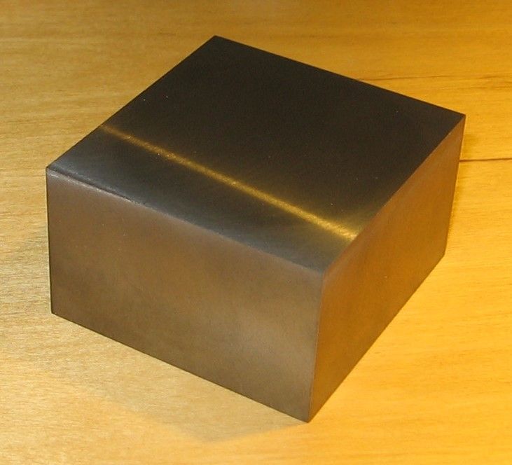
                            Well that went extremely well, no acrid smoke, no foundational tremors due to lack of rigidity, no rubbish surfaces due to insufficient power, and despite my trepidation as I entered the workshop this morning a rather enjoyable day all told. Starting with a 70mm sq by 40mm long piece of CI it has ended up 65mm by 69mm by 39mm high, which was by coincidence what I wanted. The 4 sides were done with a 5 insert 50mm cutter at 0.5mm DOC at 750rpm, the top and bottom with a 6 insert 80mm cutter at 0.3mm DOC at 700rpm. The swarf all came off as tight helical coils with very little dust which suggests the inserts were cutting well and absolutely no sign of stress on the machine.

                            img_1742.jpg

                            img_1750.jpg

                            It remains for me to extend my grateful thanks to everyone who contributed to the thread, especially Jason, the project moves forward a bit more. Now all I've left to do today is clear up the mess.

                            Kind regards

                            Martin

                            Edited By Martin Shaw 1 on 02/12/2022 16:49:49

                            #623387
                            SillyOldDuffer
                            Moderator
                              @sillyoldduffer

                              Don't forget the material matters! Cast Iron only requires about half the cutting force needed to get through mild-steel. Tool and alloy steels require up to double the force needed to get through mild-steel.

                              But as I said, it's not that a big face cutter will fail on a small mill, the problem is it can't be driven at anything like it's design speed and power. The shortcomings of a small mill don't show up when taking light cuts, they only become apparent when taking deep cuts at high rpm and feed rate. It only matters when the owner has unrealistic expectations like believing a big face cutter on a lightly rated machine will magically remove lots of metal quickly with no ill effects.

                              Dave

                              #623389
                              JasonB
                              Moderator
                                @jasonb

                                Not sure how you came to those conclusions Dave when my figures show that the face mill was the quickest option compared with a fly cutter or 4-flute milling cutter. Even if Martin had used the 4-jaw it would have taken longer, about 5min 30 on his SC3 and in the region of 2.45 if I were doing it on the 280.

                                When you take the metal removal rates for the three options including lead in & lead out but excluding rewinding time it's clear to see the face mill removes the most metal in a set time.

                                Facemill 0.14cu in/min

                                Flycutter 0.03cu in/min

                                Milling Cutter 0.09cu in/min

                                Also my speeds are as I said towards the top end of what what is suggested for these inserts so they can be driven at the top end of the design speed, infact the speed is the one thing that can generally be taken from tables, just the chipload and DOC will need reducing.

                                Thanks for the update Martin, always good to hear a happy ending. BTW how did your threads turn out with the Volkel die?


                                Edited By JasonB on 02/12/2022 19:01:15

                                #623392
                                Martin Shaw 1
                                Participant
                                  @martinshaw1

                                  Thanks Dave, I did what I wanted to do however a simple "well done" would have sufficed.

                                  Jason I'm still waiting on the dies from Rotagrip which they posted 2 weeks ago, if they aren't here tomorrow they are going to resend them.

                                  Regards

                                  Martin

                                  #623456
                                  JasonB
                                  Moderator
                                    @jasonb
                                    Posted by SillyOldDuffer on 02/12/2022 17:23:16:

                                    Don't forget the material matters! Cast Iron only requires about half the cutting force needed to get through mild-steel. Tool and alloy steels require up to double the force needed to get through mild-steel.

                                    In which case we are in luck because steel generally has a faster cutting speed than Cast Iron so we can wind the pot on out hobby machines up a bit and get that extra power out of the motor as it gets closer to it's sweet spot.

                                    Although Martin's original question was about machining cast iron as Michael said this post can serve as a guide to those thinking of trying these type of cutter on their hobby mill so I have also wasted a bit of steel this morning.

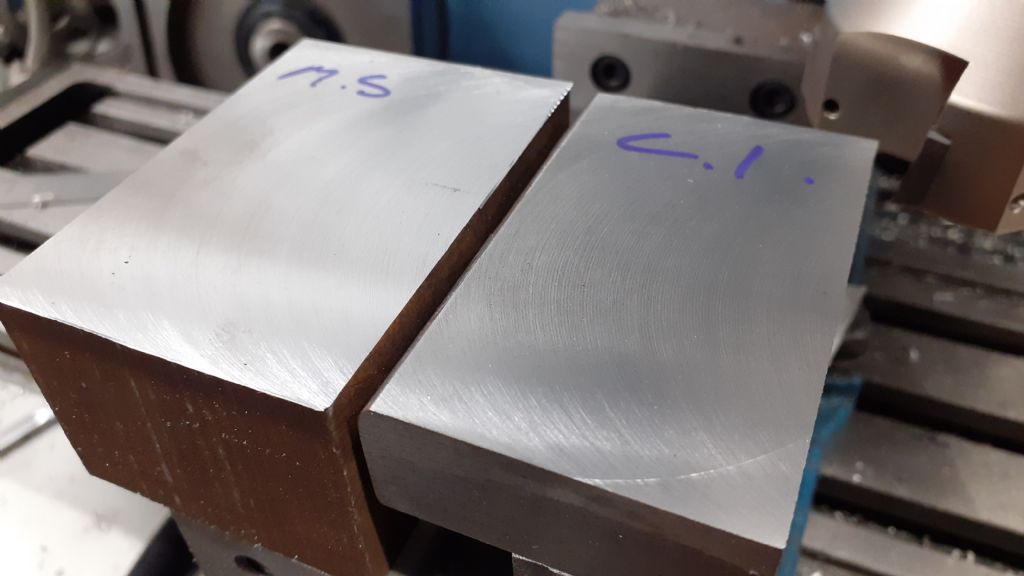
                                    In this case a piece of Dave's favorite "unknown" steel of which I was given a couple of lumps, one of which at 76mm x 51mm will serve a similar comparison to the 71mm piece of iron machined yesterday.

                                    Again the load on the machine can be considerably lightened by using APKT non ferrous inserts in the six tooth 80mm head. This time speed of 850mm was found to give a good result which equates to a machining speed of 210m/min again towards the top end of the suggested speeds for this shape of insert on low carbon steels. Timing the cut gives a feed rate of 86mm/min which equates to a chip load of 0.017mm/tooth. Cut is the full 76mm width of the block and Depth of cut again the same 0.5mm. Machine seemed happy enough and curls of swarf again suggest the inserts were cutting and not rubbing.

                                    I'll not bother to work out what it may have taken with flycutter or milling cutter as I expect results will be pro rata that for the cast iron.

                                    Not too shabby for an underpowered non rigid machinewink 2

                                     
                                    20221203_082111.jpg


                                    Edited By JasonB on 03/12/2022 18:18:50

                                  Viewing 16 posts - 26 through 41 (of 41 total)
                                  • Please log in to reply to this topic. Registering is free and easy using the links on the menu at the top of this page.

                                  Advert

                                  Latest Replies

                                  Viewing 25 topics - 1 through 25 (of 25 total)
                                  Viewing 25 topics - 1 through 25 (of 25 total)

                                  View full reply list.

                                  Advert

                                  Newsletter Sign-up