Experimental Vibration Analysis of a WM280 Lathe

Advert

Experimental Vibration Analysis of a WM280 Lathe

Home Forums Electronics in the Workshop Experimental Vibration Analysis of a WM280 Lathe

Viewing 25 posts - 26 through 50 (of 53 total)
  • Author
    Posts
  • #480540
    SillyOldDuffer
    Moderator
      @sillyoldduffer

      Interim report, I haven't given up yet.

      I got no results out of the MPU6050 based accelerometer module I was experimenting with. After reading the small print I find it was a poor choice for this application because it's designed to ignore vibration! They're intended for quadcopters and RC models where vibration interferes with direction sensing so it's filtered out by the module. I thought it was possible to read the sensors directly via an SPI interface, but it turns out to be connected to the DMP chip, not the sensors. No response to an SPI probe, so either the module is faulty or the interface does something else. I've decided to follow Leslie's pointer and get an Instrustar IS205A data-logger for my Birthday. (I am 21 again this month.)

      I bought this sensor, which is the more sophisticated of two very similar. It has digital and analogue outputs. This also is unsuitable! It's a species of knock detector, giving a measure of how big the bump was. Not very sensitive, and, given a wallop, the sensor takes several milliseconds to settle. Hopeless for detecting delicate repetitive movement. I guess the gold ended drum contains a weight on a spring as used in car alarms.

      dsc06267.jpg

      Now I'm waiting for delivery of a cheap MPU6050 unit that doesn't filter it's output. Judging by the wait it's on a slow boat from China! Andrew Johnson found a useful Article describing a similar endeavour to mine. It identifies a particular sensor that should definitely do the job. Only one small problem – they're $70 each plus post and packing from the US! (If you have to ask you can't afford it.) I hope the cheap MPU6050 unit works!

      Andrew's information confirms analysing vibration data is difficult. Rather than target the whole machine, the project concentrates on motor bearings and was able to detect problems early. If I get this to work, might be better to develop a kind of electronic stethoscope so the operator can 'listen' to suspect machines one part at a time, as a way of simplifying the data.

      Dave

      Advert
      #480560
      Joseph Noci 1
      Participant
        @josephnoci1

        Can't find my circa 2016 post on the vibration analyzer/balancer I built up ….Anyway, used software from Miklos T Koncz , a Hungarian. Built up the accelerometer sensors using ( now a bit old..) Free scale MMA7260 3 axis analogue output devices, into the laptop sound card, with an optical rotation position sensors.

        Works very well indeed – used it to balance spindles etc, up to 25K rpm.

        Might have a go and instrument the lathe…

        balancer sensors and control box.jpg

        Accelerometer modules

        accelero modules.jpg

        Sensor selection control box

        control box.jpg

        Balancing a 20Krpm spindle on a sensitive drill press.

        Red arrow is the balancing 'weight' – a small strip off adhesive aluminium tape. White circle is rpm and position center.

        balancing.jpg

        Accelerometer super-glued to support arm to measure lateral acceleration.

        balancing1.jpg

        #480564
        SillyOldDuffer
        Moderator
          @sillyoldduffer
          Posted by Joseph Noci 1 on 17/06/2020 18:06:45:

          Can't find my circa 2016 post on the vibration analyzer/balancer I built up ….Anyway, used software from Miklos T Koncz , a Hungarian. Built up the accelerometer sensors using ( now a bit old..) Free scale MMA7260 3 axis analogue output devices, into the laptop sound card, with an optical rotation position sensors.

          Works very well indeed – used it to balance spindles etc, up to 25K rpm.

          Doh! That's impressive! Balancing a spindle is a nice application and I like the graphical display too. I'm going to have to lift my game…

          Off searching for Miklos T Koncz now.

          Ta,

          Dave

          #480578
          Michael Gilligan
          Participant
            @michaelgilligan61133
            Posted by SillyOldDuffer on 17/06/2020 17:18:47:

            .

            … (If you have to ask you can't afford it.) …

            .

            Upon which topic … These are like the accelerometers we mostly used in the Lab, in the 70s and 80s

            **LINK**

            https://www.bksv.com/en/products/transducers/vibration/Vibration-transducers/accelerometers/4371

            The cables and amplifiers were also ‘not inexpensive’

            Three of those, mounted on a 1” cube, at each of several locations, was typical. surprise

            MichaelG.

            #480596
            Joseph Noci 1
            Participant
              @josephnoci1

              Yep, thats the technology of the day, back then – used many variants of those when we did the MIL-STD-810 environmental qualification tests on avionic boxes – used to close the vibration loop on the electromagnetic shakers.

              Those sensors were expensive for sure! And the Charge amplifiers likewise.

              The one in the photos still works, in my draw, with its charge amp..

              accel1.jpg

              accel2.jpg

              #480624
              Joseph Noci 1
              Participant
                @josephnoci1
                Posted by SillyOldDuffer on 17/06/2020 19:02:54:

                Off searching for Miklos T Koncz now.

                Ta,

                Dave

                Dave, seems Miklos has disappeared. Cannot find any trace of him or his doings anymore. Maybe I can help you out with his kit if you are interested….PM me..

                Joe

                #480631
                Michael Gilligan
                Participant
                  @michaelgilligan61133
                  Posted by Joseph Noci 1 on 17/06/2020 21:17:48:

                  .

                  The one in the photos still works, in my draw, with its charge amp..


                  .

                  Fond memories, Joe yes

                  MichaelG.

                  .

                  Edit: ___ seeing your note to Dave, I’ve just spotted this:

                  http://users.atw.hu/aerotarget/Balancing/Manual.pdf

                  Edited By Michael Gilligan on 18/06/2020 08:10:54

                  #480637
                  Joseph Noci 1
                  Participant
                    @josephnoci1

                    Michael,

                    Yes, I found that as well, but his web site is gone, and he does not answer his email anymore. The manual gives interesting insight, but how to obtain his software – it was inexpensive.

                    Must remember we are speaking of a dynamic balancing tool here – not at all what Dave is chasing – this tool does not do vibration analysis in the true term – just enough to do balancing.

                    Vibration analysis with a view to machine reliability analysis is a life's work and a handful of dissertations all on its own!

                    You may know the SA Rooivalk Helicopter…I had a 'small' team ( 9 people..!) working on developing a real time vib. analysis strap-on system to predicate lifetime and service interval requirements on its rotor gearbox. That was interesting – digging out the few hundred hertz gear-teeth vibrations from the wapping of the rotor blades from a few rpm to maybe 500rpm, the turbine reduction box noise, etc….There were more than a handful of TMS 320 series DSP's,…And a few maths geeks far smarter than I was on the subject!

                    #480646
                    Michael Gilligan
                    Participant
                      @michaelgilligan61133

                      Posted by Joseph Noci 1 on 18/06/2020 08:45:44:

                      .

                      Must remember we are speaking of a dynamic balancing tool here – not at all what Dave is chasing – this tool does not do vibration analysis in the true term – just enough to do balancing.

                      .

                      Understood, Joe

                      … I was just intruding on the ‘overheard‘ conversation.

                      My own experience was in the “Environmental Engineering“ test facility at BAe Dynamics [a.k.a. Army Weapons] in Stevenage.

                      MichaelG.

                      #480660
                      SillyOldDuffer
                      Moderator
                        @sillyoldduffer

                        Many thanks to Michael for finding the Miklos Kunze paper; the closest I got yesterday was a DVD advert I suspect was Gay Porn!

                        The paper's another good read with plenty of discussion of pros, cons, whys and wherefores. Koncz complements Andrew's paper, which centred on AnalogDigital MEMS technology and uses LTSpice to display waveforms as a demonstrator, rather than exploiting a sound card. It shows how digital signal analysis can detect bearing wear with data from three ADXL1002 accelerometers ($75 each). Miklos' sensors are a loudspeaker and repurposed relay coil, much cheaper, and he tackles turbine balance. I'm sort of in the middle; can lathe vibration be detected and causes identified? Is it worth doing? I don't know yet.

                        Struggling with the maths is a major challenge! I'm OK with:

                        intromaths.jpg

                        But integrals are beyond me! (Though I think Eq4 below means I could use the easier right-hand side.)

                        integral.jpg

                        Delighted to hear Joe had a couple of maths geeks on the Rooivalk Helicopter. It means I'm not the only one swamped by sums!

                        At the moment I'm exploring digital signal maths with SciPy and MatPlotLib and they probably wouldn't be the end solution. Ideally the computer should be cheap and portable so it can be used fearlessly in a workshop. So far an Arduino Nano and RaspberryPi3B both collected data successfully from a digital 6-axis accelerometer. The Raspberry has enough poke to run a TFT display or do XWindows over WiFi. The Nano isn't powerful enough to analyse the data or display it. Albeit slowly a Raspberry Pi4 could read, analyse and display results but it doesn't have a built-in Sound Card, or analogue input (to read analogue sensors). A Nucleo is an interesting possibility so I bought a F429ZI to play with: much faster than an Arduino, plus Graphics, Audio and Floating Point accelerators. Whether or not I can leverage its goodies remains to be seen!

                        Not sure yet if this is an actual project or I'm idly exploring possibilities for fun and interest! If the concepts can be made to work I'll pull them together into a build. Or maybe I'll have a melt-down on the way! (My clock-analyser project stuck when I realised it depended on a good GPS signal. My unit doesn't work reliably indoors and having to take clocks outside for testing is a bust. Nor am I cracking on with 3D-printing… )

                        Too little time, too many distractions, and insufficient discipline.

                        Dave

                        #480671
                        KWIL
                        Participant
                          @kwil

                          I have adopted a much more simplistic approach to as turned quality, if it is not acceptable.

                          Marginally change spindle speed using the VFD, load the toolholder with some form of added weight or change to a carbide boring bar which is much stiffer (and heavier).

                          #480675
                          Joseph Noci 1
                          Participant
                            @josephnoci1

                            Too little time, too many distractions, and insufficient discipline.

                            Dave

                            Thank God for that! I think, post career, that all those elements are what keeps up healthy, alive, alert and the brain active. ( sorry, what were we discussing…?dont know)

                            on your issue with the GPS signal..

                            My clock-analyser project stuck when I realised it depended on a good GPS signal. My unit doesn't work reliably indoors and having to take clocks outside for testing is a bust.

                            – I had a similar issue with a 'mobile' GPS stabilised reference oscillator – I made a sort of 'signal repeater' – I used an active GPS antenna, fed it 5v via two 10uh inductors using an SMA T connector – the antenna on one end of the T, the 5V on another, and then a 2nd , non active antenna, on the 3rd end of the T.

                            Place the active antenna outside with good sky view, and place the 2nd antenna with its business end on top of the antenna you wish to get the signal into. My antenna each had 6meter cables, so was easy to locate – Worked a charm.

                            Dave, if interested PM me your email and I can send you all I have on the Miklos system – lots of PDF's and photos of setups, quite interesting.

                            #480773
                            Neil Wyatt
                            Moderator
                              @neilwyatt

                              When I were a lad we used a penny balanced on it's edge on top of the headstock.

                              Neil

                              #480831
                              AdrianR
                              Participant
                                @adrianr18614

                                My clock-analyser project stuck when I realised it depended on a good GPS signal. My unit doesn't work reliably indoors and having to take clocks outside for testing is a bust.

                                Dave,

                                If you are using a computer that has access to the internet you do not need GPS to have an accurate clock. With the NTP daemon running your clock will be synchronized within ms to UTC.

                                Adrian

                                #480836
                                Frances IoM
                                Participant
                                  @francesiom58905

                                  there was a 2 part article on a DIY GPS synced frequency ref in Nov + Dec 2019 issues of Practical Electronics.

                                  I suspect that for the relatively short term measurements a temperature stabilised high quality oscillator would suffice

                                  #480843
                                  SillyOldDuffer
                                  Moderator
                                    @sillyoldduffer
                                    Posted by AdrianR on 19/06/2020 08:27:45:

                                    My clock-analyser project stuck when I realised it depended on a good GPS signal. My unit doesn't work reliably indoors and having to take clocks outside for testing is a bust.

                                    Dave,

                                    If you are using a computer that has access to the internet you do not need GPS to have an accurate clock. With the NTP daemon running your clock will be synchronized within ms to UTC.

                                    Adrian

                                    Hi Adrian,

                                    I was trying to do better than NTP, which is normally more than good enough for most purposes! NTP is accurate to within a few milliseconds, and then suffers jitter due to the computer's built in clock. NTP has to regularly correct computer clocks because they drift, and the software trusts computer time which is usually slightly wrong.

                                    How often computer time is corrected by NTP depends on the operating system. Linux is much better than Windows. Try Time.is : the difference between NTP and what your computer's clock believes at the moment is displayed top left. My Ubuntu computer this morning is 'exact', ie -0.004 seconds (±0.035 seconds)

                                    NTP is good but not very good. (notice ±0.035 second tolerance mentioned by time.is above)

                                    Some GPS modules output an accurate hardware seconds tick. The tick is derived from multiple satellites (more than needed for ordinary navigation) and corrected by the module for accuracy. It's possible because each satellite is in a known position and sends atomic clock standard time signals. As the receiver knows where it is on the ground, and where all the satellites are, it can apply the corrections necessary to generate a second pulse correct to within nanoseconds of atomic UTC. GPS time is as good as it's possible to get in the home and almost everywhere else!

                                    An expensive GPS unit designed for time applications can get within 1 nanosecond of true UTC. The affordable consumer module I'm using claims 10nS jitter. It's a challenge to maintain anything like that accuracy inside my code running on an Arduino, but I reckon I'm good to about 10 microseconds within each second. The long term accuracy is extraordinary because the Arduino's internal clock is corrected to GPS time once per second.

                                    The idea is to measure a mechanical clock pendulum with a much better time standard. With a GPS signal, the analyser can 'see' micro-deviations within each pendulum swing as might be due to the escapement, alignment, or vibration, and also measure long-term changes. By logging humidity, temperature and barometric pressure as well as pendulum timings, it's possible to detect errors due to the environment as well as rate errors.

                                    The idea of using an ultra-accurate clock to correct mechanical time isn't new. During the 19th Century, most astronomers were employed doing it. Their job was to compare the Observatories mechanical clock with star transit times, find the clock's rate, and calculate the necessary corrections. Every night, all night, weather permitting. Then locals would set their clocks from observatory time. Ship's chronometers were the most important customers. The observatory would also check time-pieces to determine rate errors, so that owners could correct readings. Knowing 'it runs consistently slow by 2.4 seconds per day', means the navigator can fix the error and not end up on the rocks!

                                    Dave


                                    Edited By SillyOldDuffer on 19/06/2020 10:20:55

                                    #480847
                                    Michael Gilligan
                                    Participant
                                      @michaelgilligan61133

                                      Posted by AdrianR on 19/06/2020 08:27:45:

                                      […]

                                      With the NTP daemon running your clock will be synchronized within ms to UTC.


                                      .

                                      … so a decent mechanical or electromechanical clock should be adequate for checking that devil

                                      Seriously; it‘s interesting to consider what level of accuracy and stability is being achieved when a clock’s rate is within a few tens of seconds per year; and how one might reliably check/predict that in a short-duration test.

                                      MichaelG.

                                      .

                                      Edit: posted before I had seen Dave’s response.

                                      Edited By Michael Gilligan on 19/06/2020 10:21:55

                                      #480852
                                      AdrianR
                                      Participant
                                        @adrianr18614

                                        Dave, thanks for the reply.

                                        Fascinating, I had not considered that level of measurement to check the operation of a clock.

                                        Adrian

                                        #480857
                                        Joseph Noci 1
                                        Participant
                                          @josephnoci1

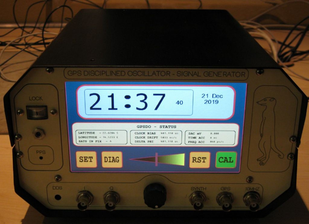
                                          My accurate Clock reference – generates a 10MHz clock, typical accuracy to 10-13.

                                          Uses an 'old' HP voltage controlled ovenised crystal oscillator, with a phase locked loop, locked in essence to the GPS 1PPS signal, with a many tap IIR filter to help. The oscillator is from a defunct HP Cesium Beam standard – the Cesium tube now dead..

                                          The GPS time can then be set to UTC, and then the 1PPS synchronized to UTC, derived from the stable crystal clock. Generally to better than 0.1 PPT…with jitter seemingly better than 1PPB – I cannot measure to better than than 1PPT, so…

                                          With a Nucleo of course..

                                          Waaayyy of topic now…

                                          Joe

                                          front main page.jpg

                                          top_open.jpg

                                          #480916
                                          SillyOldDuffer
                                          Moderator
                                            @sillyoldduffer
                                            Posted by Joseph Noci 1 on 19/06/2020 11:25:34:

                                            My accurate Clock reference – generates a 10MHz clock, typical accuracy to 10-13.

                                            Uses an 'old' HP voltage controlled ovenised crystal oscillator, with a phase locked loop, locked in essence to the GPS 1PPS signal, with a many tap IIR filter to help. The oscillator is from a defunct HP Cesium Beam standard – the Cesium tube now dead..

                                            The GPS time can then be set to UTC, and then the 1PPS synchronized to UTC, derived from the stable crystal clock. Generally to better than 0.1 PPT…with jitter seemingly better than 1PPB – I cannot measure to better than than 1PPT, so…

                                            With a Nucleo of course..

                                            Waaayyy of topic now…

                                            Joe

                                            front main page.jpg

                                            Very good! Us propeller-heads can admire the specification and the I and Q outputs while the rest of the world fall for the colour screen and Meerkat!

                                            Loveable Russian Meerkat's sell insurance in the UK; I like to remind people that Meerkats eat their young!

                                            smiley

                                            Dave

                                            #482880
                                            SillyOldDuffer
                                            Moderator
                                              @sillyoldduffer

                                              Slow progress waiting for parts to arrive, time-wasting boobs and many 'Person From Porlock' visits!

                                              Anyway, the first accelerometer module failed because it processes data to remove vibration, making it great for stabilising a quadcopter and useless for detecting vibration. So I bought a simpler module allowing its sensors to be read directly and transferred the whole project on to a RaspberryPi3B+, cost about £35. This is a small general purpose computer, considerably more powerful than an Arduino, not ideal for time-sensitive electronic control projects because it's multi-user/multi-tasking, but – unlike a PC – it exposes 40 General Purpose Input-Output (GPIO) pins suitable for electronic projects. (The closest a PC ever came to providing a hobby friendly interface is the obsolete parallel printer port.) The 3B isn't as fast as a Pi4 but it uses less power, better if the computer is run off a battery in a messy workshop.

                                              The RaspberryPi GPIO is far more delicate than an Arduino so take care – over-volting or drawing excess current might brick the whole computer, which is why PCs don't let you do it! On the plus side, the Pi has a full Linux OS with all the tools needed to capture data, crunch the numbers, and display the answers.

                                              The Pi3 and MCU6050 module are connected together thus:

                                              mpu6050circuit.jpg

                                              The 10nF, 10k and 2k resistors are needed to suppress electrical noise which in my workshop are enough to crash the I2C data link (SCL and SDA). Arduino I2C is relatively bomb-proof!

                                              In operation Pi & sensor are plonked on the headstock and powered on. Note the sensor is weighted down.

                                              dsc06279.jpg

                                              The PI connects to my home network over wifi so the program can be started remotely. It reads the sensor and – when a button is pressed – logs a stream of X,Y & Z accelerometer values to a time-stamped file. Pressing the button again closes the file. Many timestamped logs can be taken. A second program reads logfiles, does the maths, draws the graphs, and saves them as a jpg:

                                              a0627092652.dat.jpg

                                              The graphs suggest my lathe doesn't have a vibration problem at the frequencies detected by a MCU6050! The signal graph shows the module detecting small movements when cutting metal, worst when I hit the shoulder at the end. The maximum frequency detected by this set-up is 100Hz because the module can only report 200 samples per second.

                                              The FFT analysis shows no big frequency peaks. And the zoomed in signal looks like noise: random small amplitude vibrations in all directions.

                                              Neil suggested balancing a penny as a simple way of detecting vibration and my WM280 passes this test too, at any RPM:

                                              dsc06280.jpg

                                              And on the saddle, even when cutting with power traverse.

                                              dsc06282.jpg

                                              Python3 programs here.

                                              mcuaccel.py reads the sensor. The import modules used should all be pre-loaded with the Pi Rasbian operating system.  The log file is human readable.

                                              mcugraph.py does the analysis. It requires scipy, numpy and matplotlib to be downloaded and installed from the command line with:

                                              sudo apt install python3-dev
                                              sudo apt install libffi-dev
                                              sudo apt install python3-matplotlib
                                              sudo apt install python3-scipy

                                              (Installing scipy should also install numpy)

                                              Next steps – follow up on earlier comments made by Andrew, Joe and Leslie and try some different sensors! Conclusions so far: it's possible but may not be worth the effort!

                                              Dave


                                              Edited By SillyOldDuffer on 29/06/2020 12:35:54

                                              #488526
                                              SillyOldDuffer
                                              Moderator
                                                @sillyoldduffer

                                                This project ain't dead yet though I may pay someone to put me out of my misery! It's not going well

                                                In order to 'try some different sensors', I decided to build a vibration table. My lathe isn't an ideal test-bed because I don't how badly it vibrates, if at all, or at what frequencies. The vibration table is a loudspeaker in a tin box that can be fed whatever test frequencies I want. The complete set-up:

                                                vibrationtest.jpg

                                                And in real-life:

                                                dsc06300.jpg

                                                First sensor up is this MEAS device kindly provided by Leslie:

                                                dsc06288.jpg

                                                From the factory this model is weighted to resonate at 200Hz so fun with maths to investigate lifting it.

                                                measresonance.jpg

                                                Thanks to Duncan Webster sorting out the formula for me I can estimate the weight needed on Leslie's MEAS sensor for a particular resonance. Removing the original brass weights but leaving the rivet behind should give about 355Hz – about right.

                                                meassmaths.jpg

                                                Measured with the sig gen and oscilloscope, on the vibration table I actually got 415Hz.

                                                Alas, woe and thrice woe, all is not well!

                                                1. My vibration table (posh name for loudspeaker inside an old biscuit tin), has it's own resonances. Ideally the table should be acoustically flat and it isn't. Measurements are suspect.
                                                2. Although delightfully sensitive to bumps the MEAS sensor is insensitive to regular vibration at audio frequencies, except at its resonant point and third harmonic. Not good as a sensor detecting vibration equally across a spectrum.
                                                3. My oscilloscope's FFT function detects nothing. Must be doing something wrong
                                                4. You would not believe the petty hassles I've had. One example, it took longer to sort out the audio amp's jack plug and socket than to build and box the amplifier.

                                                Never mind, I can now compare various sensors in comfort to see which is best for this application.

                                                Few other observations. The MEAS sensor vibrates faster than the input signal. The sensor detects a heightened response at at least 22 frequencies between 100Hz and 3.1kHz : this may be due to biscuit tin resonances. When vibrated with a square wave, the sensor detects square at low frequencies, and triangular waves at most others. Resonance and the third harmonic are both detected as pure sine waves, presumably because the sensor is vibrating in tune.

                                                Taking much longer than expected with no useful result so far…

                                                Dave

                                                #488574
                                                Roger Best
                                                Participant
                                                  @rogerbest89007

                                                  smiley Sometimes too much information is useless because you don't know what to listen to.

                                                  25 years ago I was a machine tool designer making ultra-precision machine tools that produced optics where the material billet cost more than my annual salary. We were testing a brand new machine tool when a very clever colleague walked up, quoted a musical note, recited its frequency and walked away. I am sure our faces where something to behold.

                                                  Nowadays we all have instrumented hammers and the kit quoted in this thread.

                                                  The important frequencies are shown in your surface finish, try and estimate the number of wobbles in the surface around the circumference (or per mm), work out its frequency. That is the one that matters.

                                                  Almost perfect? Use a screwdriver to listen to the toolpost, compare to a frequency generator e.g a piano. the piano has frequencies from 27 to 4k Htz, its unlikely that you have a frequency driver outside of that range for normal machining, although possibly at the lower end. Then move around the lathe looking for where the sound comes from, either listening or tapping things to find their natural frequency.

                                                  I know all this stuff is very old-hat but it might at least verify which is the biggest "problem".

                                                  #488607
                                                  SillyOldDuffer
                                                  Moderator
                                                    @sillyoldduffer
                                                    Posted by Roger Best on 31/07/2020 21:32:05:

                                                    smiley Sometimes too much information is useless because you don't know what to listen to.

                                                    The important frequencies are shown in your surface finish, try and estimate the number of wobbles in the surface around the circumference (or per mm), work out its frequency. That is the one that matters.

                                                    I know all this stuff is very old-hat but it might at least verify which is the biggest "problem".

                                                    Good advice Roger! Ought to explain though that I'm not solving a particular issue with my lathe. Rather I'm exploring the possibility of plonking a magic box on the headstock which analyses the racket coming off any lathe and automatically points a finger at dodgy bearings, gear-train, lead-screw or motor etc.

                                                    Buying second-hand appearances can be deceptive. A grubby battered looking old lathe may be in much better condition than one tarted up by Coco the Clown for profit. Or the clean machine might be the real deal. If it can be made to work, my magic box would allow an inexperienced purchaser to identify potential lemons.

                                                    One of many obstacles to progress is I expected my noisy Chinese lathe to vibrate. As far as I can tell it doesn't have any significant vibrations, which makes it a poor test case, hence the need to build a Vibration Table.

                                                    The project is in four parts:

                                                    • Find a suitable sensor and capture vibration data from a machine, (data capture works but I'm struggling to find a suitable sensor without spending lots of money.)
                                                    • Analyse vibration data by applying a Fast Fourier Transform (working)
                                                    • Draw Graphs identifying abnormal frequencies and amplitudes. (working)
                                                    • Link frequencies to causes, such as motor speed, gear ratios, shaft rpm etc. ( not started )

                                                    Results so far suggest 'too much data' is a major problem. I'm now thinking it would be better to go for an electronic stethoscope that the operator applies to suspect parts like bearings one at a time. I knew it was ambitious before starting, but apart from the computer side, I'm mostly out of my depth. Quite Interesting though!

                                                    I agree completely about surface finish!

                                                    Dave

                                                    Edited By SillyOldDuffer on 01/08/2020 08:45:27

                                                    #488610
                                                    Michael Gilligan
                                                    Participant
                                                      @michaelgilligan61133

                                                      Good to see you progressing with this, Dave … but:

                                                      May I suggest that you re-engineer your loudspeaking shaker ?

                                                      The actual modification would depend upon the donor loudspeaker, but in essence you should replace the cone with a ‘spider’ … this keeps things nicely linear, and filters-out most of the irrelevant noise.

                                                      MichaelG.

                                                      .

                                                      Hint:

                                                      bea970c6-d85d-4ab9-bb2c-a9f2b6e9ec43.jpeg

                                                    Viewing 25 posts - 26 through 50 (of 53 total)
                                                    • Please log in to reply to this topic. Registering is free and easy using the links on the menu at the top of this page.

                                                    Advert

                                                    Latest Replies

                                                    Viewing 25 topics - 1 through 25 (of 25 total)
                                                    Viewing 25 topics - 1 through 25 (of 25 total)

                                                    View full reply list.

                                                    Advert

                                                    Newsletter Sign-up