I regret that I am unable to actively contribute to Dave’s excellent project, but I will offer what I believe to be the definitive statement about circular error: I have created this Album for convenient reference …. [ignore it if you wish]
… although “it is what it is” and therefore only of peripheral interest
MichaelG.
.
P.S. __ It would have been so much nicer if you could have ‘been bothered’ to provide that link in the first instance … we could then have been ‘on the same page’
Thanks for posting the Hope-Jones thing Michael. I'm not sure though that it is "definitive".
One thing that affects pendulum amplitude is lateral seismic vibration – actually this also affects the phase but the amplitude issue is more of a problem since it introduces errors through circular deviation, that actually increase with Q. If you look at a "stationary" high-Q pendulum with a microscope a small amount of swing at its natural frequency can be observed – of course this is not usable as a time source as its phase wanders randomly. This small seismic oscillation adds to the wanted motion, and the half of it that's in-phase causes a time error. Doug Bateman discovered the oscillation and it was analysed by Philip Woodward. I wonder if the small variations in the Shortt amplitudes could have been cause by micro-seisms? I'll have a more detailed read and try to find his primary sources.
Doug Bateman's clock is stabilised to a constant amplitude of much better than a micron which should virtually eliminate circular deviation.
Posted by Michael Gilligan on 22/12/2022 14:51:25:
What I meant was perhaps that it represents “the defining moment” in our appreciation of the problem.
MichaelG.
One might argue that the defining moment was when John Harrison found that he could compensate for pressure variation by exploiting controlled circular and escapement deviation?
.
One has been arguing that for years … but one thought the FH-J comments particularly relevant to this thread.
Posted by Michael Gilligan on 22/12/2022 17:48:50:
Posted by John Haine on 22/12/2022 15:35:34:
Posted by Michael Gilligan on 22/12/2022 14:51:25:…
…
… but one thought the FH-J comments particularly relevant to this thread.
MichaelG.
Specially when F H-J says 'It is ordained that perfection shall be elusive, and since the joy is in the chase rather than in the achievement, we must not rebel if the golden apple is held just beyond our reach.'
Dave, for your next project. Now that you have a highly accurate GPS reference signal, and a switching mechanism to deliver a power pulse to the pendulum, rather than complex (PID) math to adjust the pulse timing have you considered using the lack of isochronism in the pendulum as an inherent feedback mechanism.
…
Well I have now!
Seems a cunning wheeze, but isn't there a danger that a pendulum so governed will follow the GPS signal rather than keeping it's own time? I fear a pendulum managed with GPS in this way isn't a free-pendulum, it's a synchronous electric motor. What do the jury think, is this cheating? If so I'm tempted!
but isn't there a danger that a pendulum so governed will follow the GPS signal rather than keeping it's own time? I fear a pendulum managed with GPS in this way isn't a free-pendulum, it's a synchronous electric motor. What do the jury think, is this cheating? …
Dave
.
Well this member of the Jury agrees with your ‘fear’
As I wrote a few posts back … I am hoping that your clever electronics will tune/teach the pendulum, in such a way that it can finally be set-free without disgracing itself.
Posted by Michael Gilligan on 22/12/2022 14:51:25:
What I meant was perhaps that it represents “the defining moment” in our appreciation of the problem.
MichaelG.
One might argue that the defining moment was when John Harrison found that he could compensate for pressure variation by exploiting controlled circular and escapement deviation?
Yeay. Totally agree with that. If you cannot eliminate an error exploit it. I beleive there was evidence that on the Brocklesby Park Clock he at one stage added a vane on the rear of the pendulum to increase the effects of changing air density. Harrison was possibly unique in his time for using large amplitudes in his pendulums as a consequence of his grasshopper escapement. Dead beat escapements gave a much smaller swing and thus less circular error to play with.
Seems a cunning wheeze, but isn't there a danger that a pendulum so governed will follow the GPS signal rather than keeping it's own time? I fear a pendulum managed with GPS in this way isn't a free-pendulum, it's a synchronous electric motor. What do the jury think, is this cheating? If so I'm tempted!
Dave
Cheating. You might as well just have a clunky pendulum set to run a tad fast, let it increment your counter 30 times then disconnect and wait until it gets a synch pulse from the GPS divided by 30. Michael described an earlier implementation here. There's a moving picture here
No more "cheating" than any other mechanism used to get the pendulum to accurately match a GPS derived time signal.
As you said a few posts further back in the discussion about PID control to deal with long time constants, "The clock compensates on every beat". So every beat you are adjusting the power to keep the pendulum in sync with the time standard. I was just suggesting a different (and possibly simpler) way to do that.
Both approaches achieve the same end, adjusting the power pulse to compensate for external (temp, pressure etc.) or internal (friction, cyclic error etc.) variations in rate.
There is nothing to stop you measuring the stability of the power pulse length, and working to minimise its size and variability by tweaking the mechanical and environmental conditions.
No more "cheating" than any other mechanism used to get the pendulum to accurately match a GPS derived time signal.
[…]
.
But in any system that *only* does that, the pendulum is ultimately just decorative
Come the nuclear armageddon we might need to use our pendulums as actual timekeepers, so I see Dave’s experiments [and the others] as a step on the path to understanding. … As Duncan has already mentioned, it is rather pointless just having a mechanical device which reliesupon a better timekeeper.
As I suggested earlier, real success will come when Dave’s system has *taught* his pendulum to work sufficiently accurately that the reference signal can be disconnected.
Rather like that big day when the stabilisers finally come-off your kid’s bike !
Posted by Michael Gilligan on 22/12/2022 23:17:01:
…real success will come when Dave’s system has *taught* his pendulum to work sufficiently accurately that the reference signal can be disconnected.
The teaching process is about the timing and length of the pulse duration.
If Dave can "teach" his clock so that the power pulse is sufficiently accurate that it delivers the power needed to offset losses, and starts at the point which ensures that the trailing edge of the power pulse is exactly aligned with the falling edge of the reference pulse, then my system doesn't need the reference pulse either.
But as soon as you remove it everything will start to change!
For the pendulum-nut, correcting the rate so that the pendulum is synchronised to GPS (i.e. phase locking it) is anathema! GPS derives its time ultimately from the terrestrial clock ensemble that defies UTC, most of those clocks using rubidium or caesium oscillators. The point of making pendulum clocks in this day and age is to see how closely a pendulum can match the time reference. If you wanted an accurate clock then just use GPS and a display!
Though actually making a GPS disciplined oscillator (GPSDO) even with well behaved OCXOs is not a trivial task – would be harder I suspect with a pendulum oscillator.
Prof. Robertson in 1925 attempted to discipline his pendulum to Greenwich Time using the method I outlined above. Though he did some very innovative things, including inventing a phase/frequency detector that only emerged in electronics in 1971, the system didn't work very well, primarily because barometric pressure changes in practice are too fast to track if you only have one reference pulse a day.
No more "cheating" than any other mechanism used to get the pendulum to accurately match a GPS derived time signal.
As you said a few posts further back in the discussion about PID control to deal with long time constants, "The clock compensates on every beat". So every beat you are adjusting the power to keep the pendulum in sync with the time standard. I was just suggesting a different (and possibly simpler) way to do that.
…
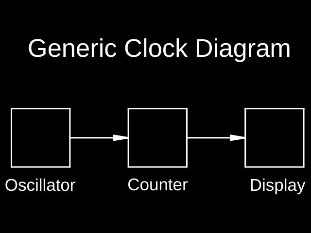
Ah, a misunderstanding! Here's a block diagram of a clock:
Typical oscillators are the earth's rotation, pendulums, balance wheels, quartz crystals, and the vibration of certain atoms. The perfect oscillator is stable, it doesn't drift, jitter, and it maintains a steady output no matter what. There is no perfect oscillator. Pendula are sensitive to temperature, air pressure, vibration, tidal effects, and possibly humidity. All friction is bad, as is any physical change in the bob, rod or suspension.
The counter is any device that counts beats and divides them into something useful such as Hours, Minutes, and Seconds. It also allows the clock to be set to a particular time. In a mechanical clock the counter is a fixed ratio gearbox.
The display is any device that converts the counter output into human useful form – the hands of a clock, or a digital display.
It's important to isolate these stages from each other. The Display mustn't effect the Counter, and the Counter mustn't effect the Oscillator. This is quite difficult to do in a mechanical clock, and pendula are very sensitive to outside influences, especially impulses, temperature and air pressure.
My clock minimises impulse problems by removing all physical connections to the pendulum. The escapement is replaced by an Infra-red beam and an electromagnet. I have accurate control over when the pendulum is impulsed, and impulse strength. In practice so far, these have been reduced manually to the point where the clock runs reliably. They could be used synchronise the pendulum to GPS, but aren't.
A conventional pendulum clock compensates for temperature mechanically in the pendulum, usually by exploiting the different expansion rates of two metals. One way is to partially fill the bob with Mercury. When the temperature rises the rod expands and would alter the timing, except the Mercury also expands, lifting the bob's centre of mass by rising inside it, and counter-balancing whatever the rod does. I'm not doing anything like that.
Instead of compensating the pendulum, I correct it's errors in the counter. My counter is a microcontroller, where the ratios are implemented in software. In addition to counting pendulum beats, it also reads temperature, pressure and humidity. After testing the clock over a long period, I know what the pendulum's period should be at any given temperature, pressure and humidity, and can compensate for them in the counter, not in the oscillator.
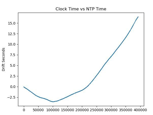
For this scheme to work the pendulum has to be reasonably well-behaved, which it isn't yet. I can compensate for reliable changes, but not for variations caused by unknown factors. This graph is giving me grief, it shows my clock is drifting and is fast compared with NTP:
What I don't understand is why the clock drifted slow at first, and then switched to drifting fast. It's not temperature or pressure related. If the rod were stretching or something like that the drift would be constant in one direction, not a tick shaped curve.
Forum friends have suggested improvements to my over simple suspension design, which could be buckling the suspension spring. When I get the chance I'll make a new one, but xmas and a family crisis are taking priority.