On the question of putting a clock in a sealed tank, and possibly pumping out the air, I wonder how important the stiffness of the tube is? Imagine it was a thin membrane, then obviously differential air pressure would just deflect it to ensure the inside and outside pressures were equal. If it was thick steel or glass, there's be no significant deflection so the inside pressure would be constant. PVC drainpipe is somewhere in between – though if all the air was pumped out there would be zero inside pressure anyway. There must be some relationship between all these, has anyone come across any analysis?
Thanks Michael, I'll be interested in your thoughts.
.
Well … whilst installing the latest map update on my GPS, it seemed opportune to read the article.
I may not be clever enough to understand your concerns, John … but it all seems thoroughly well-reasoned to me.
It’s a test-set, not a controller, and it aims to overcome the recognised deficiencies in other such tools.
They note that ‘GPS time’ is the best low-cost [to the user!] reference available, and they are using the 1PPS pulse.
They have cleverly avoided the need to measure the amplitude of the pendulum swing, by inferring it from velocity measurements [a stroke of genius, in my opinion]
They are sampling at 15 second intervals, which seems a sensible compromise between long-term and short-term, and provides plenty of opportunity for data-processing in ‘real time’
The various tasks are appropriately distributed between the two Arduinos and the ‘Cloud’ … the data being also saved locally for off-line processing.
The practical result shown in Figures 6 and 7 is surely ‘the proof of the pudding’
Quite honestly … I can’t see what they could have possibly done better for the price, and it’s definitely on my “must have a go at that” list.
On the question of putting a clock in a sealed tank, and possibly pumping out the air, I wonder how important the stiffness of the tube is? […] There must be some relationship between all these, has anyone come across any analysis?
.
I’ve not seen anything, John … but my gut-feeling is that the perceived problem would be trivial in the grand scheme of things, because is would only be causing a very small variation in an already small variable.
The Shortt clocks used a copper tank, and Jim Arnfield used a gas cylinder for his twin-pendulum.
A length of plastic water-pipe or underground drainage pipe would I think do nicely for the impoverished experimenter. … Whatever comes to hand when passing the road-works or building-site !!
On the question of putting a clock in a sealed tank, and possibly pumping out the air, I wonder how important the stiffness of the tube is? … PVC drainpipe is somewhere in between – though if all the air was pumped out there would be zero inside pressure anyway. There must be some relationship between all these, has anyone come across any analysis?
No, but I pumped my 4½" drainpipe out with my ancient Edwards rotary vane vacuum pump without it collapsing. Despite the pump being an old banger it seems to work OK, but I've no way of measuring low pressures. Whatever it is I can't pull the top off when the pump is running.
Posted by Michael Gilligan on 13/12/2022 14:19:12:
Posted by John Haine on 13/12/2022 11:24:08:
Thanks Michael, I'll be interested in your thoughts.
.
…
They note that ‘GPS time’ is the best low-cost [to the user!] reference available, and they are using the 1PPS pulse.
They have cleverly avoided the need to measure the amplitude of the pendulum swing, by inferring it from velocity measurements [a stroke of genius, in my opinion]
They are sampling at 15 second intervals, which seems a sensible compromise between long-term and short-term, and provides plenty of opportunity for data-processing in ‘real time’
…
MichaelG.
Haven't read the article yet but it sounds similar to my effort, at least in part. For example, I too infer amplitude from velocity and use GPS pulse per second to calibrate the clock. (Actually NTP at the moment.)
I decided not to compromise on sampling interval, and log every beat. Generates a shade over 9Mb per day. That's about 3.3Gb per year, which my 32Gb RAM machine could handle without having to use disc storage, though it would take a while to crunch the numbers. Not too scary. Too much for a Raspberry Pi 3B, though the little thing could analyse a years worth of 15 second logging if one didn't mind having a coffee break whilst waiting.
If the objective of running the pendulum in the tank is to avoid barometric disturbance then the tank need not be a vacuum, partial pressure is sufficient to insulate from atmospheric fluctuations. The remaining effect is density changes with temperature variations, with a lower pressure these will be reduced. Unless you are going to continuously pump small leaks may cause issues which will be much less of a problem with a smaller differential pressure.
regards Martin
Well, I may be missing something but as I read it the pendulum ticks and GPS pps are compared by each creating an interrupt to the smaller Arduino, which measures the time between the interrupts in 4us intervals. What happens if the pendulum isn't swinging at 0.5 Hz and the pulses slide past each other? Or if it is at 0.5 Hz very nearly and the interrupts are overlapping for long periods?
My point about pipes is just that in the spectrum between a membrane and a thick steel cylinder the inside pressure and outside do have some relationship, I just wondered how significant it was. If what you want to do is just minimise barometric sensitivity there is an amplitude for every pendulum where it will be zero – as with Clock B.
My point about pipes is just that in the spectrum between a membrane and a thick steel cylinder the inside pressure and outside do have some relationship, I just wondered how significant it was. […]
.
As the practical scope for pressure variations inside, outside, or twixt the two, is probably much less than 1bar … I’m happy to stick with my gut-feeling that its significance is “trivial in the grand scheme of things, because it would only be causing a very small variation in an already small variable.”
MichaelG.
.
Edit: __ took the opportunity to correct a previous typo in the self-quotation [ is it ]
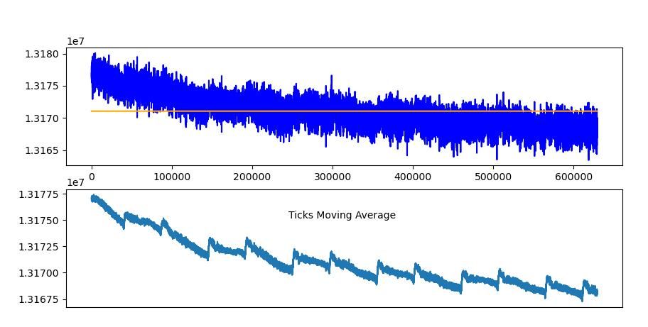
I've been getting my head round applying compensation, and from the log can simulate how the clock would behave at any given combination of pressure and temperature.
If I apply correction to match the average temperature and average pressure during a 5 day run, the results are very encouraging. NTP measured the run at 518086.0 seconds, and the compensated clock ticks add up to 518085.99999999936s.
The orange line on the graph is the compensated result, nice and straight with the temperature bumps removed, and the increased speed due to low air pressure adjusted.
Not quite where I need to be yet because the result is compensated for average temperature and average pressure, which develop during the run. Extracting the correct time statistically after the event isn't the same as having the clock correct itself beat by beat in real time.
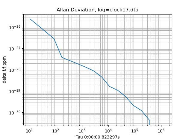
Chapter 18 of my copy of Rawling's "The Science of Clocks and Watches", tackles 'The Measurement of Clock Performance.' I believe the chapter, authored by Phillip Woodward, is a later addition. Recording my pendulum's timings with microsecond precision reveals lots of jitter; considered as an oscillator my pendulum is unstable, not good behaviour even though the instability evens out on average:
Chapter 18 discusses oscillator stability, which are all forms of frequency modulation caused by White, Pink, and Red Noise. White noise is due to random factors and is unavoidable. Even a mechanically perfect clock suffers white noise inaccuracy. However, an atomic clock is considerably less noisy than my pendulum!
A statistical technique called 'Allan Variance', detects white noise as a -0.5 slope. A zero gradient slope means the clock has Pink Noise, also caused Flicker Noise. The cause is unclear, but associated with complex systems. And when you look closely, pendula are remarkably complicated!
A positive gradient indicates Red Noise, or 'Random Walk FM'. It means the oscillator exhibits random changes of rate: one cause being a pendulum rod suffering 'spontaneous changes of length' because Invar is an unstable alloy. I suspect the matrix of my carbon fibre rod is also unstable, and perhaps so is its stainless steel spring – possibly work hardening.
After compensation, my clock's Allan Variance is spectacularly good, an almost perfect -0.5 slope!
No champagne yet. The graph screams 'fake' at me. I think it shows that my compensating calculations are smoothing out pink and red noise, not that my pendulum really has high stability. The maths is a sharp filter, hiding reality. An interesting point is that the fake may not matter if the maths causes the clock to successfully emulate a high-performer. Mechanical qualities replaced by predicting in software what the pendulum should do, and the clock tweaking the results to make them perfect. If you can't tell the difference, the fake must be OK. Hmmm.
Whilst playing with the numbers, I reset the real clock so it counts the average period found after 5 days, and also reduced impulse power. Be interesting to see how that plays out. I feel I'm get close to putting the PVC pipe on and pumping out the air. Pride comes before a fall!
If the objective of running the pendulum in the tank is to avoid barometric disturbance then the tank need not be a vacuum, partial pressure is sufficient to insulate from atmospheric fluctuations. The remaining effect is density changes with temperature variations, with a lower pressure these will be reduced. Unless you are going to continuously pump small leaks may cause issues which will be much less of a problem with a smaller differential pressure.
regards Martin
Agreed, except low pressure also improves Q because the bob doesn't have to stir air. Worth doing if I can make it work. But I'm already worried about leaks, and how to attach a heavy hose and pump to a light-weigh construction without disturbing a pendulum known to be very vibration sensitive. The machining of the clock base is pretty rough too, highly likely to leak.
My point about pipes is just that in the spectrum between a membrane and a thick steel cylinder the inside pressure and outside do have some relationship, I just wondered how significant it was. …
Ah, with you, I don't know. Should be small, because it's altering the residual pressure of a vacuum, but it must depend on how good the vacuum inside is. A perfect vacuum wouldn't change at all, but I suppose a mild vacuum could be pressured noticeably. The more I understand this the more ignorant I turn out to be.
Posted by Michael Gilligan on 13/12/2022 14:19:12:
They note that ‘GPS time’ is the best low-cost [to the user!] reference available, and they are using the 1PPS pulse.
[…]
Haven't read the article yet but it sounds similar to my effort, at least in part. For example, I too infer amplitude from velocity and use GPS pulse per second to calibrate the clock. (Actually NTP at the moment.)
[…]
.
I’m sure you know all about this, Dave … and have taken account of it in your analysis of results … but for the benefit of those dipping into this discussion I will just quote a few words from the article in HJ
Network Time Protocol (NTP) server time, whilst accurately disciplined to GPS or a national time standard over the long term, does not provide an accurate enough short-term reference for the sorts of measurements we wish to perform, due to delays in network routing.
I know very little about pendulums, but I do appreciate that multiple sources of oscillation can cause interesting interaction effects
Might it be that your pendulum support is not rigid enough in the horizontal plane? In other words, might the three long pillar support not be sufficiently rigid side to side and allow a very small horizontal movement, which could cause perturbations?
Dave’s design & development has, quite reasonably, been targeting the novel aspects of his system … and it is all going rather well … but ultimately, he will need to mount the pendulum on something better-approximating bedrock.
I suspect that the present structure will have quite low torsional stiffness, and that even Dave’s lightweight pendulum will be forcing some vibration in that mode.
The enclosing vessel should, if suitably attached, stiffen the structure considerably.
Posted by Michael Gilligan on 13/12/2022 23:19:02:
Posted by SillyOldDuffer on 13/12/2022 14:57:37:
Posted by Michael Gilligan on 13/12/2022 14:19:12:
They note that ‘GPS time’ is the best low-cost [to the user!] reference available, and they are using the 1PPS pulse.
[…]
Haven't read the article yet but it sounds similar to my effort, at least in part. For example, I too infer amplitude from velocity and use GPS pulse per second to calibrate the clock. (Actually NTP at the moment.)
[…]
.
I’m sure you know all about this, Dave … and have taken account of it in your analysis of results … but for the benefit of those dipping into this discussion I will just quote a few words from the article in HJ
Network Time Protocol (NTP) server time, whilst accurately disciplined to GPS or a national time standard over the long term, does not provide an accurate enough short-term reference for the sorts of measurements we wish to perform, due to delays in network routing.
MichaelG.
That's right. You mentioned being confused earlier by my results spanning less than a microsecond to several days. It's because the experiment applies two different timing techniques. The Arduino provides a microscopic view of the time taken by each swing with a resolution of about 62 nano-seconds, but not that accurate. It can detect tiny variations in periodicity, and I'm able to see quite quickly that the pendulum isn't isosynchronous.
I haven't compared how noisy my pendulum is compared with a well-made rigid big one. I think mine is poor, and part of the trouble might well be due to the tripod moving as John Doe suggests. My design assumed the tripod is rigid compared with the force applied by a light bob swinging over a short arc, which only gets a tiny impulse. I could be wrong!
The nano-second view doesn't provide long term accuracy. For that I've used GPS, or NTP. To avoid vibration the clock is set-up in a North facing bedroom where the GPS module doesn't get a good enough view of the satellites. So I've switched to NPT via Wifi, which at worse is always within 100mS of reality. This makes it suitable for measuring the long-term performance of the clock, ie how well or badly the nano-second measurements add up over a long time.
The Mk1 clock used the whole fibre rod as a spring rather than being a true pendulum – a Webster Bendulum. Didn't work well enough to justify running it in a vacuum. Performance with a conventional spring suspension is markedly better, despite warts – now I can see air-pressure affecting period, which I think is a major step forwards.
A number of improvements are in the pipeline. Cold and a family problem have kept me out of the workshop but I'm itching to make a better suspension and bob.
Posted by Michael Gilligan on 14/12/2022 18:49:20:
A request, please, Dave …
Could you please either describe how you are inferring the amplitude of your swing, or point me to where you have already so done ?
I have searched through this thread, and the best I found was:
”Relative amplitude is measured as the length of time the beam is broken.”
I’m not trying to criticise … I am trying to understand.
…
Happy to be criticised! If I've got something wrong it needs to be fixed. Also open to better ways of doing things too, so suggestions welcome.
I hope the diagrams and words make what I'm doing clear, and it's valid.
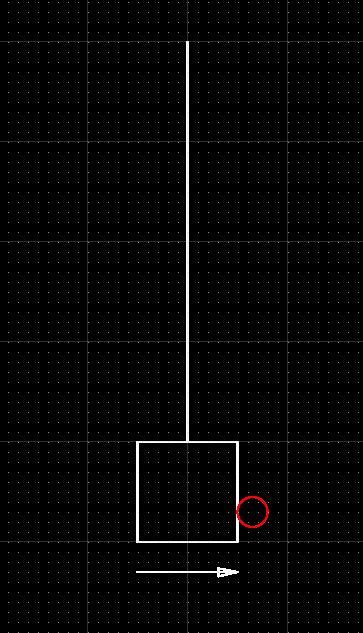
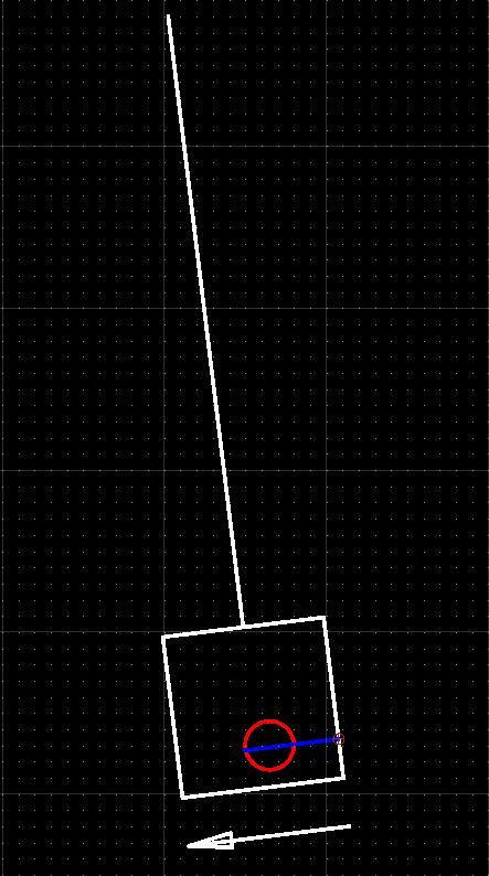
First diagram shows the bob at bottom dead centre, swinging to the right and just about to enter the IR beam marked in red:
The bob carries on until it breaks the beam. The time between break events is the pendulum's period.
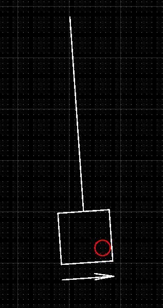
However the bob is still moving past the beam, which remains broken until the bob swings back and uncovers the beam.
So the time the beam remains broken depends on how far the bob moves past the beam and takes to swing back to uncover it. The time is measured with high resolution, and, because pendula are isosynchronous, the time is proportional to amplitude. What I call 'Relative Amplitude' is the ratio between time beam is broken and period.
By the by, I thought you'd provided a link to Arduino based clock measuring project described in a recent Horological Journal article. Unfortunately the link is to the authors and I haven't subscribed to HJ.
John Haine asked how they got better than 4uS accuracy from GPS. If they used a Mega 2560 I think I know the answer. Arduino boards don't always expose the necessary pins, and their documentation is thin on timers, but I recently found the Mega exposes two 16MHz hardware timers. One can be used to measure the actual frequency of the Arduino's crystal (number of crystal clock pulses in exactly one GPS second), whilst the other measures the frequency of the pendulum in the same units. At the moment my Mega / GPS test rig shows the the arduino's 16MHz crystal is actually 15997857Hz. The measurement can be improved by averaging over several seconds, and then used to calibrate the pendulum numbers.
To answer John's 4uS question, the 16bit counter runs at 16MHz, taking 4096uS to overflow. The interrupt increments an overflow count, and has 4096uS to do it. Counting is stopped and started by pendulum events, also at hardware level. The stop event copies the current count into a register and generates a different interrupt. The function also has 4096uS to do the necessary, which is to calculate overflows*maxCount + current count, and set a flag telling the main loop that a result is available. The answer depends on hardware clock speed, not the 4uS software limit imposed by micros().
"John Haine asked how they got better than 4uS accuracy from GPS. If they used a Mega 2560 I think I know the answer. "
That wasn't really my question. Actually they publish the code on Github and the relative timing is done by a Nano. The micros() time is taken when interrupts occur on 2 pins and they are compared. micros() has a resolution of 4us I think, at least on the Nano. But my main concern is the fact that the Nano is comparing the phase of two asynchronous processes, except in the case when the pendulum is exactly at 0.5Hz. So the phases will slowly slide past each other, and while they are nearly in-phase I'm not sure what the interrupts do, but anyway you would see big phase jumps as well as the slow roll. I guess it might be possible to post-process the data in the Mega but they don't say anything about that.
I've had a go at the change in internal pressure of a sealed containment due to an increase in atmospheric pressure. It's a tad simplified because I've ignored Poisson ratio effects and the resistance of the extra internal pressure. Starting with internal and external pressure of 950mBar and increasing the external to 1050 mBar changes the internal pressure from 95000 Pa (950 mBar) to 95000.4001 Pa for a steel tube, or 95020.0083 Pa for PVC. This is because PVC has a much lower young's modulus. I have a feeling that my simplifications will exaggerate the effect.
In the unlikely event of anyone wanting the sums send me a pm with your email address