Experimental Pendulum Clock

Advert

Experimental Pendulum Clock

Home Forums Clocks and Scientific Instruments Experimental Pendulum Clock

Viewing 25 posts - 51 through 75 (of 562 total)
  • Author
    Posts
  • #623556
    duncan webster 1
    Participant
      @duncanwebster1

      I can see how that works, but the impulse is a long way from the centre of mass. Interesting to see how well it works

      Advert
      #623564
      Mick B1
      Participant
        @mickb1

        When I refurbished a master clock pendulum for the railway last year, it had 2-off 0.0075" thk spring steel suspension – 1 broken, 1 pitted. The suspension gap I didn't measure exactly, but I think 10 – 12 mm.

        I bought new pendulum suspension steel from Ian T. Cobb – he's on the web, can be paid by PayPal, and responded quickly to my order. I bought 150mm of .008" x 1/2" spring steel. I think I had to trim it with scissors or tinsnips to get the width right.

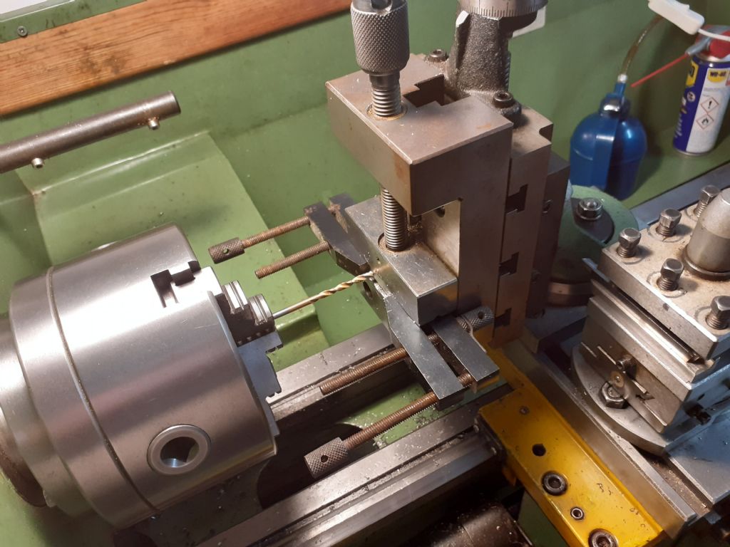
        I found I could comfortably drill it without major distortion or burring if I sandwiched it between 2 bits of alli strip with parallel clamps, as per pic:-

        suspstripdrill.jpg

        I don't know how much adjustment it took from the railway's setup expert, but somebody told me a few days ago the clock and its slaves were still keeping good time.

        #623569
        Martin Kyte
        Participant
          @martinkyte99762
          Posted by duncan webster on 04/12/2022 12:50:45:

          I can see how that works, but the impulse is a long way from the centre of mass. Interesting to see how well it works

          All longcase clocks impulse at the top portion of the rod and sychronomes do too. Harrison maintained that impulse arms/crutches be no more than one twelfth of the distance down the rod from the suspension point. The ideal point of impulse is however at the middle of the swing which conventional escapements don’t give you. I’m not sure that impulsing the bob is advantageous but I’m open to persuasion.

          regards Martin

          #623570
          duncan webster 1
          Participant
            @duncanwebster1

            It's intuitive to impulse at the centre of percussion so that the impulse force doesn't put any side load on the suspension. However on my theory that it doesn't matter what you do as long as you do it every time I doubt it makes much difference. Jim Radford made a clock where the point of suspension was moved side to side to keep it going, that was before microprocessors made it possible to measure things with such detail

            Edited By duncan webster on 04/12/2022 14:30:21

            #623577
            Michael Gilligan
            Participant
              @michaelgilligan61133

              Whilst we are planning Dave’s route to pendulum-perfection … Let’s hear it for Fedchenko:

              **LINK**

              http://www.leapsecond.com/hsn2006/pendulum-tides-ch5.pdf

              MichaelG.

              #623734
              duncan webster 1
              Participant
                @duncanwebster1

                This thread has prompted me to take a break from the current stalled project and make another clock. This time I want to make one based on this, but with a monstrously long pendulum, just as a feature, not a phenomenally accurate time piece. The coil in this is wound on a 30mm diameter former. Is this optimum? Instinctively I'd have thought smaller, but I have very little knowledge of magnetic fields (for very little read nil).

                Edited By duncan webster on 05/12/2022 18:46:19

                #623745
                John Haine
                Participant
                  @johnhaine32865

                  It depends on the amplitude of swing. The coil should be small relative to this. The one I described here has a 1 Hz pendulum and about 25mm amplitude, the coil is about 10mm diameter and came from an old printer where it operated an interlock. I removed the core There's a 2x3mm neodymium magnet at the end of the rod. I guess you could scale up from that?

                  #623939
                  SillyOldDuffer
                  Moderator
                    @sillyoldduffer

                    Even though still running on the old suspension. today's results are encouraging. The clock gained 10.36s in 19:33 hours, an error of 147 parts per million. Some way to go! In comparison:

                    • Ordinary quartz crystal about 100ppm (error 8.46s/day)
                    • Temperature compensated crystal about 20ppm (1.73s/day)
                    • Shortt Clock, about 1mS per day
                    • Oven Controlled Crystal, about 1 part per billion (84.6 microseconds per day)
                    • Ordinary Atomic Clock, about 0.001 ppb (84.6 nanoseconds per day)
                    • Atomic Clock Standard. 0.0001ppb (8.46nS/day)

                    What I believe the graphs are telling me:

                    clock17ticks.jpg

                    There is no obvious sign in the tick timings that the controversial side impulse causes the pendulum's period to vary. The impulse is magnet ON for about 320uS, causing about 1 swing in 3 to be impulsed, effect of Relative Amplitude below

                    clock17ra.jpg

                    The relative amplitude has a small jitter that could probably be improved by making the impulse even shorter.

                    clock17ce.jpg

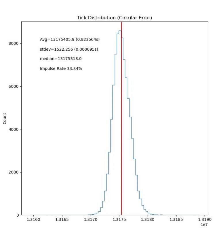
                    Circular Error has improved by a factor of about 10, but the distribution is slightly skewed, slow ticks predominating. Reason unknown.

                    clock17tbh.jpg

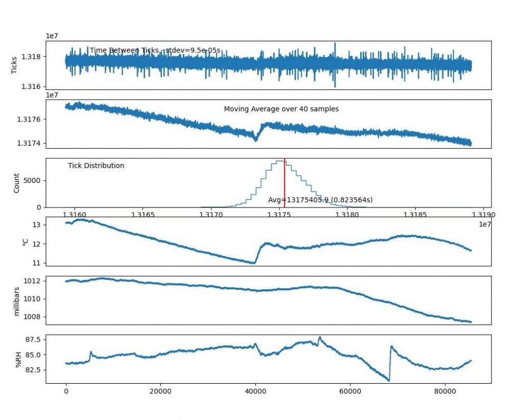
                    The comparative graphs strongly suggest a correlation between temperature and ticks aka period. The temperature and tick moving average curves are very similar, including a bump when my central heating comes on. The moving average shows the clock tending to speed up over time, cause unknown.

                    The clock's performance may be better than 147ppm, which is an error 0.014714%. Apart from not being temperature compensated, the clock times on the assumption that the pendulum's period is 0.823685s. Not so: it's NPT measured average period is 0.823564s, introducing an error of 0.014692% Not going to claim anything because it may be a coincidence, but if the figures are trustworthy the clock's actual error might be only 0.000022%. Too good to be true I feel!

                    Dave

                    #623987
                    Marcus Bowman
                    Participant
                      @marcusbowman28936

                      Perhaps:

                      https://www.analog.com/media/en/technical-documentation/data-sheets/ds3231.pdf

                      I believe boards containing this chip are available for the Arduino, although it doesn't really require much interfacing so could go on a generic breadboard-style shield or a bit of perf board.

                      Marcus

                      #623996
                      duncan webster 1
                      Participant
                        @duncanwebster1

                        Now that I've realised that Dave impulses his pendulum at the centre even tho his electromagnet is at the end my reservations have evaporated

                        #624021
                        SillyOldDuffer
                        Moderator
                          @sillyoldduffer
                          Posted by duncan webster on 08/12/2022 00:52:06:

                          Now that I've realised that Dave impulses his pendulum at the centre even tho his electromagnet is at the end my reservations have evaporated

                          The original clock had rather complicated software that fired the pulse 'n' microseconds after the bob broke the beam. As it was fiddly to set-up, I changed the code ages ago to fire the pulse immediately the beam is broken. Sorry if that wasn't made clear at the time.

                          However, because the beam is offset from the bob the impulse isn't applied conventionally when the bob is travelling at maximum speed, but nor is it applied when the bob is moving very slowly.

                          Period is measured as the time between beam breaks.

                          Relative amplitude is measured as the length of time the beam is broken.

                          The magnet is pulsed when relative amplitude falls below a threshold. At the moment, the threshold is a guess, and the pulse length tweaked manually after inspecting the graphs. I'm trying to find the combination of impulse power and threshold that keeps the pendulum swinging reliably at constant amplitude.

                          The clock can be told to alter the threshold and pulse length whilst it's running, so it might be possible for the remote program doing the statistics to home in on the combination, if there is one, that produces the most regular pendulum movements.

                          Mustn't get too carried away. There are mechanical improvements on the to do list. Most urgently I want to make a suspension as described by John, fitted with a longer thinner spring as suggested by Michael.

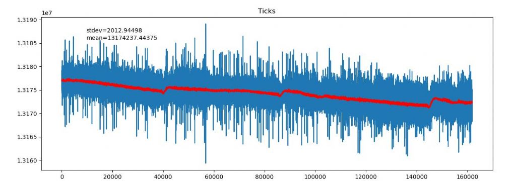
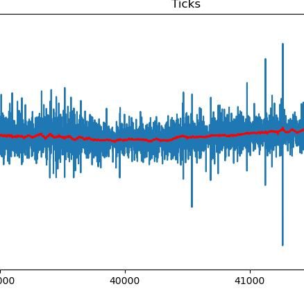
                          This morning's graph shows the need for temperature compensation: the red line is the moving average, smoothed over 40 samples, and jumps caused by the central heating coming on are obvious.

                          clock17-1ticks.jpg

                          The graph also shows the pendulum is slowing down overall. I don't know why: the effect doesn't seem to relate to temperature or humidity, but it might be air pressure. Good news if the pendulum is responding to pressure, but I'm not confident my construction is good enough. Other possibilities are the pendulum lengthening due to the super-glue giving way, or the suspension spring pulling out of the clamps.

                          Dave

                          #624023
                          John Haine
                          Participant
                            @johnhaine32865

                            Quite likely to be early "ageing"? I suspect it would take perhaps months for the period to settle.

                            #624024
                            Michael Gilligan
                            Participant
                              @michaelgilligan61133

                              Posted by SillyOldDuffer on 08/12/2022 10:28:42:

                              […]

                              This morning's graph shows the need for temperature compensation: the red line is the moving average, smoothed over 40 samples, and jumps caused by the central heating coming on are obvious.

                              clock17-1ticks.jpg

                              The graph also shows the pendulum is slowing down overall. I don't know why: the effect doesn't seem to relate to temperature or humidity, but it might be air pressure. Good news if the pendulum is responding to pressure, but I'm not confident my construction is good enough. Other possibilities are the pendulum lengthening due to the super-glue giving way, or the suspension spring pulling out of the clamps.

                              Dave

                              .

                              I am intrigued by the pendulum’s apparently rapid response to the switching of the Central Heating, Dave

                              … I would have expected more latency, due to thermal inertia of the components, and to [presumed] insulation by an enclosure.

                              Perhaps I am mis-interpreting the graph

                              MichaelG.

                              #624027
                              SillyOldDuffer
                              Moderator
                                @sillyoldduffer
                                Posted by Marcus Bowman on 07/12/2022 22:37:18:

                                Perhaps:

                                https://www.analog.com/media/en/technical-documentation/data-sheets/ds3231.pdf

                                I believe boards containing this chip are available for the Arduino, although it doesn't really require much interfacing so could go on a generic breadboard-style shield or a bit of perf board.

                                Marcus

                                Yes, the DS3231 is a good chip and available as an Arduino Module complete with a back-up battery. Various libraries make it easy to use and accuracy is good, say 4ppm. Cost around £5.

                                Although accuracy is good, DS3231 precision is low for my purposes, its 32.768kHz output is about 31mS, when I'm measuring the pendulum's period in 16MHz ticks, about 62.5nS. The extra precision enables me to see tiny changes in period, but – unlike a DS3231 – the accuracy of an ordinary 16MHz crystal isn't good enough for long term time measurements. For that I'm using Network Time Protocol, which is high accuracy but low precision.

                                In an earlier version, I used a DS3231 to calibrate the Arduino's crystal on the fly, comparing how long the Arduino thought a 32kHZ DS3231 pulse was, and applying compensation to Arduino measurements so they matched the DS3231, in a sense locking the Arduino oscillator to the DS3231.

                                This version didn't last long because I switched to a GPS module. When these have enough satellites in view, they output ultra accurate second pulses, much better than a DS3231. But they only work when the GPS receiver has a good view of the southern sky, which it doesn't at the moment.

                                For that reason, I should go back to a DS3231! It would temperature compensate and improve the accuracy of my fast measurements, well worth doing. Many thanks for the suggestion!

                                Dave

                                #624034
                                SillyOldDuffer
                                Moderator
                                  @sillyoldduffer
                                  Posted by Michael Gilligan on 08/12/2022 10:49:43:

                                  Posted by SillyOldDuffer on 08/12/2022 10:28:42:

                                  […]

                                  This morning's graph shows the need for temperature compensation: the red line is the moving average, smoothed over 40 samples, and jumps caused by the central heating coming on are obvious.

                                  Dave

                                  .

                                  I am intrigued by the pendulum’s apparently rapid response to the switching of the Central Heating, Dave

                                  … I would have expected more latency, due to thermal inertia of the components, and to [presumed] insulation by an enclosure.

                                  Perhaps I am mis-interpreting the graph

                                  MichaelG.

                                  Well, the scale exaggerates the size of the bump. Zooming in makes it less obvious:

                                  clock17zoomedbump.jpg

                                  On this scale the far less obvious bump extends over roughly 2050 beats. As each beat averages 0.823491s, that's about 30 minutes. Doesn't seem unreasonable to me, but I know very little about real pendulum clocks.

                                  The clock isn't in it's enclosure and it's fairly close to the radiator.

                                  Dave

                                  #624038
                                  Michael Gilligan
                                  Participant
                                    @michaelgilligan61133

                                    Posted by SillyOldDuffer on 08/12/2022 11:37:29:

                                    […]

                                    On this scale the far less obvious bump extends over roughly 2050 beats. As each beat averages 0.823491s, that's about 30 minutes. Doesn't seem unreasonable to me, but I know very little about real pendulum clocks.

                                    The clock isn't in it's enclosure and it's fairly close to the radiator.

                                    Dave

                                    .

                                    Thanks for the clarification, Dave yes

                                    I confess that scaling the plot to accommodate the combination of ‘about 30 minutes’ and ‘seconds to six places of decimals’ befuddled the old brain a little.

                                    MichaelG.

                                    #624046
                                    duncan webster 1
                                    Participant
                                      @duncanwebster1

                                      Confused…. The graph is of time for one tick, and ticks are getting shorter. This means it is gradually speeding up. The central heating warms it up and so makes the pendulum longer and makes tick time longer as I'd expect. I can't think of an explanation apart from senility on my part

                                      #624048
                                      Martin Kyte
                                      Participant
                                        @martinkyte99762

                                        Carbon fibre temp coefficient can be negative.

                                        regards Martin

                                        #624077
                                        SillyOldDuffer
                                        Moderator
                                          @sillyoldduffer
                                          Posted by duncan webster on 08/12/2022 12:26:12:

                                          Confused…. The graph is of time for one tick, and ticks are getting shorter. This means it is gradually speeding up. The central heating warms it up and so makes the pendulum longer and makes tick time longer as I'd expect. I can't think of an explanation apart from senility on my part

                                          How about senility on my part, blush?

                                          The ticks are getting faster and the pendulum is speeding up. Duncan's right, I got it the wrong way round. Also, checking the graphs again, there's a clear correspondence between period and temperature! Duncan's right about that too.

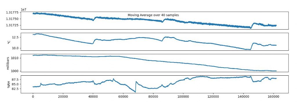
                                          clock17tempcorr.jpg

                                          Interesting because the Mk1 pendulum was almost entirely carbon fibre and had a low temperature correlation. Now the rod has a brass and steel spring suspension, the correlation is stronger. So, back to the statistics to establish the correlation factor with a regression test, and then correct the tick count by applying a formula in the clock's software. This has always been part of the plan: analysing the log reveals the size of any correlation between temperature, air pressure and humidity, and. because the microcontroller measures them, the period can be corrected by the clock numerically.

                                          Dave

                                          #624123
                                          duncan webster 1
                                          Participant
                                            @duncanwebster1

                                            Looks like the combined effect of temperature and humidity. According to this the expansion coefficient of carbon fibre composite is 0.74 e-6 per degree C, which is very small indeed. Brass is 19 e-6 and steel is ~12 e-6. Aluminium is 23, so if you fit an aluminium sleeve of the correct length under the bob so it pushes the bob up as temperature rises it should be possible to tune out the temperature effect. Make the sums easier by having the interface twixt ally and bob at half the bob height. Come to think of it the bob expands as well, so having the support from the rod at the right height might just do it without ally sleeve. To a clanky this feels a lot more satisfying than measuring temperature and compensating for it

                                            Compensating for humidity needs a material which changes its size with humidity in a predictable way, and that material will also have a temperature effect. Once you've got the outer sleeve in place humidity variation should be much smaller, especially if you arrange some silica gel inside the enclosure and change it periodically

                                            #624135
                                            Joseph Noci 1
                                            Participant
                                              @josephnoci1
                                              Posted by duncan webster on 08/12/2022 21:48:09:

                                              To a clanky this feels a lot more satisfying than measuring temperature and compensating for it

                                              thumbs up!!

                                              #624157
                                              duncan webster 1
                                              Participant
                                                @duncanwebster1

                                                Oops, read the scales wrong, barometric pressure looks like the culprit, not humidity

                                                #624173
                                                SillyOldDuffer
                                                Moderator
                                                  @sillyoldduffer
                                                  Posted by duncan webster on 09/12/2022 10:01:29:

                                                  Oops, read the scales wrong, barometric pressure looks like the culprit, not humidity

                                                  It still does!

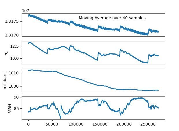
                                                  clock17envon9-12.jpg

                                                  Don't quite believe it myself, especially as ageing must be a strong possibility too. I'm going to let the clock carry on logging until the pressure rises. If the period slows down in line with it, I'll accept the evidence.

                                                  I know clunkies won't care for electronic compensation, but this is an experimental clock. It has the advantage of keeping the mechanics simple: it's just a frame, suspension, rod, bob, IR beam and electromagnet. Everything else is software.

                                                  But I accept the need to improve the pendulum mechanically and am grateful for advice received. I'll publish a 3D-CAD model of the new pendulum and suspension later.

                                                  Dave

                                                  #624177
                                                  Michael Gilligan
                                                  Participant
                                                    @michaelgilligan61133

                                                    Posted by SillyOldDuffer on 09/12/2022 11:26:05:

                                                    […]

                                                    I know clunkies won't care for electronic compensation, but this is an experimental clock. It has the advantage of keeping the mechanics simple: it's just a frame, suspension, rod, bob, IR beam and electromagnet. Everything else is software.

                                                    […]

                                                    .

                                                    Mmm … I recall similar logic being applied [once-upon-a-time] to ‘record turntables’

                                                    devil MichaelG.

                                                    #624178
                                                    John Haine
                                                    Participant
                                                      @johnhaine32865

                                                      I know that CF is supposed to be sensitive to humidity but I doubt that this is particularly a problem in a clock. The polymer matrix may change its size, but with a decent weight bob the load will be taken by the fibres not the matrix and the fibres are not affected by humidity AFAIK. My first clock had a 7kg weight on a 10mm dia 1mm wall tube, the new one has 5kg on a 6mm tube. Water is taken up by the matrix, but the change in mass according to something on the NAWCC website if at most 0.3% w/w, and if you take into account the very light weight of CF compared to the bob the effect on timekeeping is minimal. However such measurements as I have done do not include humidity, the next system will have a humidity sensor as well…

                                                    Viewing 25 posts - 51 through 75 (of 562 total)
                                                    • Please log in to reply to this topic. Registering is free and easy using the links on the menu at the top of this page.

                                                    Advert

                                                    Latest Replies

                                                    Viewing 25 topics - 1 through 25 (of 25 total)
                                                    Viewing 25 topics - 1 through 25 (of 25 total)

                                                    View full reply list.

                                                    Advert

                                                    Newsletter Sign-up