Experimental Pendulum Clock

Advert

Experimental Pendulum Clock

Home Forums Clocks and Scientific Instruments Experimental Pendulum Clock

Viewing 25 posts - 501 through 525 (of 562 total)
  • Author
    Posts
  • #633724
    duncan webster 1
    Participant
      @duncanwebster1

      By my understanding, as far as it goes, the super accurate clock is only needed to establish the relationship between pressure, temp, etc with period. After these are known, accurate clock is no longer needed, you only need a fairly 'crude' processor to alter the electronic gear ratio between the pendulum and the display in response to measured environment conditions.

      Edited By duncan webster on 16/02/2023 14:15:09

      Advert
      #633742
      Martin Kyte
      Participant
        @martinkyte99762
        Posted by duncan webster on 16/02/2023 14:13:40:

        By my understanding, as far as it goes, the super accurate clock is only needed to establish the relationship between pressure, temp, etc with period. After these are known, accurate clock is no longer needed, you only need a fairly 'crude' processor to alter the electronic gear ratio between the pendulum and the display in response to measured environment conditions.

        Edited By duncan webster on 16/02/2023 14:15:09

        That’s quite profound Duncan. Essentially you are saying if you know the rate of the oscillator and how it varies with environmental conditions you can just keep a running count modifying the interval by the correction. It seems to me with that approach you should keep the impulse constant and not attempt to correct for amplitude.

        regards Martin

        #633757
        SillyOldDuffer
        Moderator
          @sillyoldduffer
          Posted by Martin Kyte on 16/02/2023 16:06:55:

          Posted by duncan webster on 16/02/2023 14:13:40:

          By my understanding, as far as it goes, the super accurate clock is only needed to establish the relationship between pressure, temp, etc with period. After these are known, accurate clock is no longer needed, you only need a fairly 'crude' processor to alter the electronic gear ratio between the pendulum and the display in response to measured environment conditions.

          Edited By duncan webster on 16/02/2023 14:15:09

          That’s quite profound Duncan. Essentially you are saying if you know the rate of the oscillator and how it varies with environmental conditions you can just keep a running count modifying the interval by the correction. It seems to me with that approach you should keep the impulse constant and not attempt to correct for amplitude.

          regards Martin

          Duncan and Martin neatly capture what's novel about this clock in a nutshell. Yup, that's the concept.

          I think Martin's suggestion that the impulse should be kept constant is correct. It's how the clock is configured at the moment. It does seem to keep better time than when the bob was only impulsed if the amplitude fell below a certain threshold.

          More for completeness than in any belief it will be an improvement, I'm going to try keeping amplitude steady between two values by varying impulse power. Worth trying, but  my gut says Martin's suggestion will turn out to be correct.

          As an aside, the clock's 'running count' is kept as two integers representing the number of seconds and microseconds since Jan 01 1970 UTC. This being a standard time format means it's not difficult for the electronic gear ratio to retrieve an entire date-time group from it. A few moments ago the seconds count was 1676567814, which decodes to Thursday 16th February 2023 17:16:54 UTC. Because the clock knows day, month and year just as well as hours and minutes, it's fairly easy to add bling like phases of the moon, Easter, or Pacific Standard Time etc. It also means, because the counter stores seconds in a 32-bit binary integer, that the clock will fail in 83 years at 06:28:16 precisely on Sunday February 7th 2106. That's bad planning for you!

          Dave


          Edited By SillyOldDuffer on 16/02/2023 17:47:53

          #633763
          Martin Kyte
          Participant
            @martinkyte99762

            That certainly makes thing clearer regarding what you are attempting to do. I have to admit I thought you were attempting to compensate for environmental factors using impulse variation, clearly wide of the mark.

            My remark on constant impulse brings circular error within the environmental characteristics of the oscillator and thus rate variations and keeps impulsing out of it.

            regards Martin

            #633764
            Martin Kyte
            Participant
              @martinkyte99762

              Oh and rather than Bling like moon phases you could generate a calculated gravitational variation and lob that into the rate correction too.

              😊

              #633767
              duncan webster 1
              Participant
                @duncanwebster1

                If you want constant impulse, and I can see the argument, then John Reynolds falling ball has a lot going for it, no need to worry about constant voltage (or current) supplies, gravity doesn't change much if you stay in one place. However, buoyancy will change the apparent mass of the ball, so impulse not constant unless in vacuum. All very complicated.

                #633780
                SillyOldDuffer
                Moderator
                  @sillyoldduffer

                  Pi-Hut wasted no time sending the Ublox GPS I ordered: it arrived before lunch!

                  Soldered it up and wrote some code, and it does it's stuff including PPS output. Downloaded ucenter ready to see if I can alter the frequency tomorrow. Wine, telly and bed now – I need a rest!

                  Dave

                  #633798
                  John Haine
                  Participant
                    @johnhaine32865
                    Posted by duncan webster on 16/02/2023 18:34:24:

                    … However, buoyancy will change the apparent mass of the ball, so impulse not constant unless in vacuum. All very complicated.

                    Um, buoyancy surely changes the apparent weight not mass? There is another effect, "accession to inertia", caused by a mass of air being carried along by the bob which adds to its mass but not its weight since it isn't actually attached. These two effects are usually assumed to be more or less equal and they both work to the same end.

                    I have an uneasy feeling that the "open-loop feed-forward" method of correction will not work very well unless the amplitude is controlled. Air drag affects amplitude, but if the density changes the amplitude does not change immediately, because of the pendulum Q. The time constant for a high Q pendulum can be very long, for a seconds pendulum with Q of 10,000 it is 20,000/pi ~= 6000 seconds. On the other hand the change due to buoyancy is instant. So the period correction term for a change in pressure has to have terms to cope with both and the amplitude part has to model the transient behaviour. Easy to separate out the regression coefficients for a system without memory but I'm not sure how to do this if it does. On the other hand if you control the amplitude closely the problem goes away.

                    #633799
                    John Haine
                    Participant
                      @johnhaine32865
                      Posted by SillyOldDuffer on 16/02/2023 20:25:07:

                      Pi-Hut wasted no time sending the Ublox GPS I ordered: it arrived before lunch!

                      Soldered it up and wrote some code, and it does it's stuff including PPS output. Downloaded ucenter ready to see if I can alter the frequency tomorrow. Wine, telly and bed now – I need a rest!

                      Dave

                      I'm eager to know if I should buy one Dave!

                      #633804
                      Martin Kyte
                      Participant
                        @martinkyte99762
                        Posted by John Haine on 16/02/2023 22:23:08:

                        Posted by duncan webster on 16/02/2023 18:34:24:

                        … However, buoyancy will change the apparent mass of the ball, so impulse not constant unless in vacuum. All very complicated.

                        Um, buoyancy surely changes the apparent weight not mass? There is another effect, "accession to inertia", caused by a mass of air being carried along by the bob which adds to its mass but not its weight since it isn't actually attached. These two effects are usually assumed to be more or less equal and they both work to the same end.

                        I have an uneasy feeling that the "open-loop feed-forward" method of correction will not work very well unless the amplitude is controlled. Air drag affects amplitude, but if the density changes the amplitude does not change immediately, because of the pendulum Q. The time constant for a high Q pendulum can be very long, for a seconds pendulum with Q of 10,000 it is 20,000/pi ~= 6000 seconds. On the other hand the change due to buoyancy is instant. So the period correction term for a change in pressure has to have terms to cope with both and the amplitude part has to model the transient behaviour. Easy to separate out the regression coefficients for a system without memory but I'm not sure how to do this if it does. On the other hand if you control the amplitude closely the problem goes away.

                        Maybe changes the apparent mass and the actual weight.? or maybe the apparent mass is the weight? That was meant lightheartedly by the way.

                        On a more serious question for my own enlightenment:-

                        Don’t you have to have a proportional element and an integral element to the rate correction for pressure changes John? or is that what you just said. I’m imagining an experimental step change in pressure producing a proportional change in rate plus an integral term that changes the rate over time. I could see that being used as a rate correction mechanism.

                        regards Martin

                        #633812
                        duncan webster 1
                        Participant
                          @duncanwebster1

                          Mea culpa, only nuclear fission would reduce the mass. The ball I was referring to is part of the gravity escapement, not the pendulum bob, hence with higher density air you'd get less impulse and higher drag, which would reduce amplitude, but the increased buoyancy would also reduce the apparent force acting down on the bob, and so change the period. It's too late to work out whether these 2 effects add up or cancel.

                          I share John's unease about allowing for environmental effects which take a long time to have their full effect. If you had a double suspension spring (as I think John has) you could actually measure the pendulum rod temperature rather than assuming it followed air tem. Second best put another stationary piece of rod material in the same containment and measure that.

                          #633899
                          SillyOldDuffer
                          Moderator
                            @sillyoldduffer
                            Posted by John Haine on 16/02/2023 22:25:54:

                            Posted by SillyOldDuffer on 16/02/2023 20:25:07:

                            Pi-Hut wasted no time sending the Ublox GPS I ordered: it arrived before lunch!

                            Soldered it up and wrote some code, and it does it's stuff including PPS output. Downloaded ucenter ready to see if I can alter the frequency tomorrow. Wine, telly and bed now – I need a rest!

                            Dave

                            I'm eager to know if I should buy one Dave!

                            Yes you can, not as easy as expected, but it works. I'll write up what I did in the Precision Pendulum thread.

                            Dave

                            #633907
                            John Haine
                            Participant
                              @johnhaine32865

                              Excellent, thanks! I have ordered one!

                              #633912
                              duncan webster 1
                              Participant
                                @duncanwebster1

                                Having had a think, I can see why vacuum chamber is attractive, eliminates buoyancy, drag, etc issues. I wonder if the office junior's first and last job of the day was to check the level of vacuum and pump if necessary. And how did he check, a mercury barometer would be affected by ambient pressure, must have been aneroid. 

                                Gravity escapement a la synchronome gives equal impulse either side of centre, so will have less effect on period. If you had a split vane on the pendulum and a slotted opto with a magnet on the pendulum you could arrange similar with electrical drive, as the vane approaches and passes centre it goes on+, off, on-, off, so it is attracted towards centre and then pushed away

                                Edited By duncan webster on 17/02/2023 18:06:16

                                #633920
                                Michael Gilligan
                                Participant
                                  @michaelgilligan61133
                                  Posted by duncan webster on 17/02/2023 18:04:03:

                                  Having had a think, I can see why vacuum chamber is attractive, eliminates buoyancy, drag, etc issues. I wonder if the office junior's first and last job of the day was to check the level of vacuum and pump if necessary. And how did he check, a mercury barometer would be affected by ambient pressure, must have been aneroid.

                                  […]

                                  .

                                  I’ve just found this, Duncan: **LINK**

                                  https://catalog.antiquorum.swiss/en/lots/lot-16-149

                                  There’s an interesting note in the closing paragraph.

                                  MichaelG.

                                  #633927
                                  Martin Kyte
                                  Participant
                                    @martinkyte99762

                                    Fascinating Michael. That’s several very interesting pieces of information particularly the sweet spot on the amplitude matching the adjustment of the suspension. Particularly liked the happy accident of the loose suspension. It’s amazing how many major breakthroughs are initiated by accidents and mistakes. The magic is having a scientist or engineer who realises the significance of the event. Flemming with his contaminated culture dish which killed all his cells but identifies the contaminant and writes it down. Roentgen discovering X-rays because the emissions from a Crookes tube he was using to examine cathode rays lit up a floured cent screen that formed no part of his experiment. The list is endless. I wonder how much has been missed because people didn’t realise what they had got and just chucked everything as a mistake.

                                    regards Martin

                                    Edited By Martin Kyte on 17/02/2023 20:04:34

                                    #633995
                                    John Haine
                                    Participant
                                      @johnhaine32865

                                      There are a couple of errors in the Antiquorum blurb. In particular it describes the impulse current as being controlled by a switch but in fact on the achF3, which this one is, there was a 2-transistor circuit connected to two coils on the same former, connected to 2 pnp germanium transistors in a blocking oscillator circuit. Two transistors were used I think because the transistors of the time didn't have much gain – later versions of the same circuit have been widely used, for example in Mumford's clocks, those fake "pendulum" quartz movements, and even in solar powered "nodding flowers" and such like. The transistors were biased very slightly on but not enough to initiate the circuit. When the pendulum swung one way the transistors were biased off by the induced pulse, but in the other direction they were biased on and this triggered a single current pulse to the coils to impulse the pendulum. The later versions, using usually one transistor, can use only one coil and usually impulse in both directions as the coil configuration is different. There was also a design that replaced everything with a PIC processor and I've built a version using an Arduino (described on here somewhere).

                                      By the way there is another thread on Fedchenko running where I posted a reference to a Philip Woodward article in HJ that includes some dimensions that were actually taken from another article either in HSN or the NAWCC bulletin.

                                      Edited By John Haine on 18/02/2023 12:36:55

                                      #634025
                                      SillyOldDuffer
                                      Moderator
                                        @sillyoldduffer

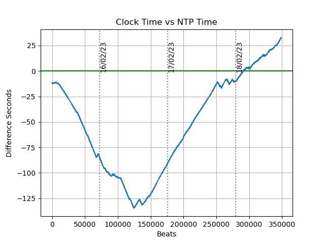
                                        Whilst busy playing with the M8Q GPS oscillator, I've let the clock run just to see what it does. Seems to be zigzagging:

                                        1802drift.jpeg

                                        No idea why!

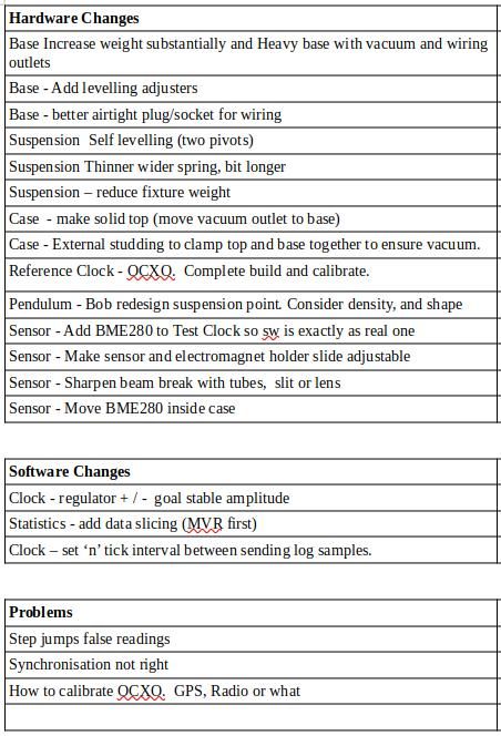
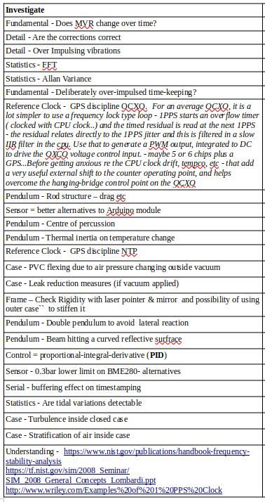
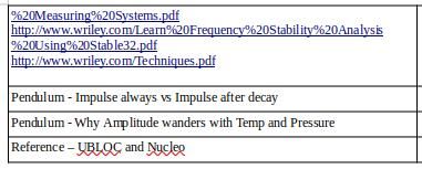
                                        Also wrote up my TO DO list:

                                        listpt1.jpg

                                        todopt2.jpg

                                        todopt3.jpg

                                        Too much!

                                        Dave

                                        #634040
                                        Joseph Noci 1
                                        Participant
                                          @josephnoci1

                                          You mentioned in your post in the precision pendulum thread WRT using the ublox pps output- you need 10MHz, etc….

                                          10MHz comes with bad jitter – read my posts – you can only use 1,2,4,8,12,24Mhz. ALL other frequencies have moderate to very bad jitter. Change your reference timebase to suit, say , 12MHz, or change the pendulum to a 10/12 rate, ie, a 0.83333hz pendulum….after all , you are really only interested in stability detrmination, not 'actual' time ( are you?) – Call it the SOD-Second…

                                          I think it was mentioned to feed the clock into a DDS chip and use that to generate the 10MHz – not really a good idea, – to get a low jitter 10MHz clock from the DDS the DDS input clock really needs to be 3 to 4x Nyquist, so 40MHz, which you can't get from the UBLOX. Some DDS chips have a PLL clock mulitiplier to generate 100MHz plus from low rate clocks ( 8MHz, etc), but the phase jitter from the PLL is high enough for it to reflect in the DDS output frequency as well, depending on the clock to output clock relationship.

                                          The Si5351 is a better option for this – you can set the Ublox to 24MHZ, and feed that to the Si5351 clock input., and set it to generate 10MHz, which it does cleanly.  But that is another dark road, and deviating from your path…

                                          If using the UBLOX to provide a 10MHz clock as measurement reference timebase you will reach the noise floor very quickly in Allan Variance.

                                          And here I am opening my mouth again…

                                          Edited By Joseph Noci 1 on 18/02/2023 19:24:30

                                          #634055
                                          SillyOldDuffer
                                          Moderator
                                            @sillyoldduffer
                                            Posted by Joseph Noci 1 on 18/02/2023 19:18:53:

                                            You mentioned in your post in the precision pendulum thread WRT using the ublox pps output- you need 10MHz, etc….

                                            10MHz comes with bad jitter – read my posts – you can only use 1,2,4,8,12,24Mhz. ALL other frequencies have moderate to very bad jitter. Change your reference timebase to suit, say , 12MHz, or change the pendulum to a 10/12 rate, ie, a 0.83333hz pendulum….after all , you are really only interested in stability detrmination, not 'actual' time ( are you?) – Call it the SOD-Second…

                                            I think it was mentioned to feed the clock into a DDS chip and use that to generate the 10MHz – not really a good idea, – to get a low jitter 10MHz clock from the DDS the DDS input clock really needs to be 3 to 4x Nyquist, so 40MHz, which you can't get from the UBLOX. Some DDS chips have a PLL clock mulitiplier to generate 100MHz plus from low rate clocks ( 8MHz, etc), but the phase jitter from the PLL is high enough for it to reflect in the DDS output frequency as well, depending on the clock to output clock relationship.

                                            The Si5351 is a better option for this – you can set the Ublox to 24MHZ, and feed that to the Si5351 clock input., and set it to generate 10MHz, which it does cleanly. But that is another dark road, and deviating from your path…

                                            If using the UBLOX to provide a 10MHz clock as measurement reference timebase you will reach the noise floor very quickly in Allan Variance.

                                            And here I am opening my mouth again…

                                            Always glad to hear what you have to say Joe.

                                            Yes, I knew the M8 jitters unless the output frequency divides into 48MHz because you told me!

                                            The M8Q is more about providing options than a particular need for it to generate jitter free 10MHz. What I'm after is a stable frequency source as a way of calibrating other frequencies. For example, I have a 10MHz OCXO which will do, except I'd like to adjust it as close to 10MHz as I can get, hence interest in GPS. One reason for wanting a better 10MHz source is I the various equipments I have that are improved by plugging one in.

                                            The other reasons are pendulum related. At the moment I'm using Arduino's which are with a max external clock input of 6.4MHz. Dividing the OCXO gets me 5MHz, but I hope I can get an equally stable 6MHz from the UBLOX, which provides more resolution.

                                            If I switch from Arduino to a Nucleo, PET I'm hoping the M8Q will give better accuracy and resolution with 12, 16 or 24MHz as a timer input, or maybe by using the M8Q to clock the Nucleo instead of a crystal.

                                            I'm hoping to understand Allan Variance one day!

                                            Dave

                                            #634058
                                            Joseph Noci 1
                                            Participant
                                              @josephnoci1

                                              Noted…however, 6MHz will have a lot of jitter…But if you set up for 24MHz, then divide by two twice, you get a VERY clean signal, stable, and since the 24MHz is relatively jitter free, dividing by 4 will 1/4 the intrinsic remnant of jitter as well!

                                              If you wish to use the GPS clock source to calibrate the OCXO better, divide the OCXO by 5 then 2 to give 1:1mark/space 1MHz, and set the GPS clock to 8MHz, and divide it by 2,2,2,2 to get 500KHz with very low Jitter.

                                              Feed both into the TI TDC7200 chip and read the delta, or even easier, use a dual trace 'scope. chan-1 triggered on a 500KHz, edge, and the 1MHz GPS clock edge into chan-2. Adjust the OCXO so that the GPS clock edge stands still WRT the 500KHz edge, and you are on frequency…

                                              And then breath a little loudly and start chasing the OCXO edge up and down the screen…

                                              Edited By Joseph Noci 1 on 18/02/2023 20:37:39

                                              #634094
                                              Michael Gilligan
                                              Participant
                                                @michaelgilligan61133
                                                Posted by SillyOldDuffer on 18/02/2023 20:25:44:

                                                Posted by Joseph Noci 1 on 18/02/2023 19:18:53:

                                                […]

                                                I'm hoping to understand Allan Variance one day!

                                                Dave

                                                .

                                                This **LINK** is so far over my head that it must be in orbit

                                                http://www.wriley.com/index.htm

                                                … but it may be of interest to you chaps.

                                                See especially : **LINK**

                                                http://www.wriley.com/paper2ht.htm

                                                MichaelG.

                                                #634101
                                                Joseph Noci 1
                                                Participant
                                                  @josephnoci1

                                                  How does one consolidate the confusing cross pollination developing on these related posts?

                                                  In a related thread – Yet another Arduino Clock thread…I posted:

                                                  A very good ppt presentation by a master in the field:

                                                  **LINK**

                                                  A veritable bible on the subject: Handbook of Frequency Stability analysis.

                                                  **LINK**

                                                  Some measurement systems:

                                                  **LINK**

                                                  And Misc good stuff:

                                                  **LINK**

                                                  **LINK**

                                                  WJ Riley is a master in this field…

                                                  And since these related posts are rather active the info rolls down the page and is gone.. Some of the related threads are going down non-MEW paths, what with GPS, Allan Variance, etc, but for the Pendulum Chasers, and for me, hugely interesting.

                                                  #634109
                                                  Michael Gilligan
                                                  Participant
                                                    @michaelgilligan61133

                                                    Apologies for my duplication of a tiny morsel from your reference set, Joe

                                                    I confess I had not yer dared to follow your links.

                                                    MichaelG.

                                                    #634116
                                                    Joseph Noci 1
                                                    Participant
                                                      @josephnoci1

                                                      Morning Michael – I see no need for you to apologise for anything! It's in the morphology of threads that so much useful info gets lost simply due to passage of posts. There have been many a beef about the 'poor' forum software/structure/way of working and I have never really agreed with these beefs – I do think it works well, EXCEPT for a search mechanism that works properly, not by devious routes, googling, standing on one leg, with binoculars in eye, etc…When I find a thread of interest I set aside time to read all posts to sieve out the gems, but sometimes its just to much – lots of guff inside good, long, threads is enough to rather set the thread aside.

                                                      Enough, lest I really take this thread down a dark road and are banned..

                                                      Soldier On Michael!

                                                    Viewing 25 posts - 501 through 525 (of 562 total)
                                                    • Please log in to reply to this topic. Registering is free and easy using the links on the menu at the top of this page.

                                                    Advert

                                                    Latest Replies

                                                    Viewing 25 topics - 1 through 25 (of 25 total)
                                                    Viewing 25 topics - 1 through 25 (of 25 total)

                                                    View full reply list.

                                                    Advert

                                                    Newsletter Sign-up