Experimental Pendulum Clock

Advert

Experimental Pendulum Clock

Home Forums Clocks and Scientific Instruments Experimental Pendulum Clock

Viewing 25 posts - 26 through 50 (of 562 total)
  • Author
    Posts
  • #623027
    SillyOldDuffer
    Moderator
      @sillyoldduffer

      Two steps forward, three steps back!

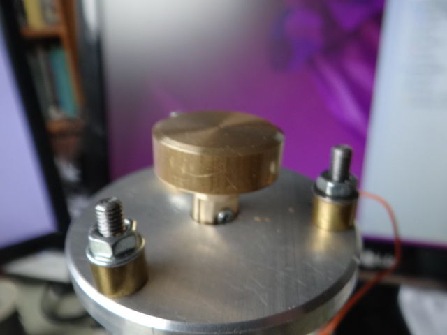
      After yesterday's power cut I moved the clock downstairs to make adjustments and noticed the top-cap wasn't seated correctly on the support tubes. (They sit in sockets.) So the top plate wasn't straight, embarrassingly visible in this earlier photo: dsc06651.jpg

      Correcting the assembly error dropped the bob so it just touches the base, so I made a new suspension piece lift it a few millimetres.

      dsc06648.jpg

      Dismantling, I dropped the screw and the clamp on the floor, both bounced and took an age to find. On discovering the head of the clamp screw fouls the mounting hole, I got fed up, watched 'Jackass the Movie' instead and thought about taking up knitting!

      This morning the central heating failed to come on, fingers crossed I've fixed it.

      I had a quick look at the code to see if Peter's miscounting hypothesis holds water. The jury's still out. I found code dealing with both 'tick' and 'tock', but the 'tock' function seems to be about measuring how fast the pendulum is moving. Although it works, I don't remember how or why! More importantly I haven't confirmed my pendulum detect logic is correct, so Peter might be right.

      Anyway, what I need to do next is fix the mechanical problems and run the clock again for at least a day. Whilst doing that I shall look at all the posts. I've also been reading what Rawlings says about pendulums and suspensions in "The Science of Clocks and Watches'. I see I've been naive: it's another job requiring a wet-towel wrapped around my head!

      Dave


      Edited By SillyOldDuffer on 29/11/2022 10:35:22

      Advert
      #623063
      SillyOldDuffer
      Moderator
        @sillyoldduffer

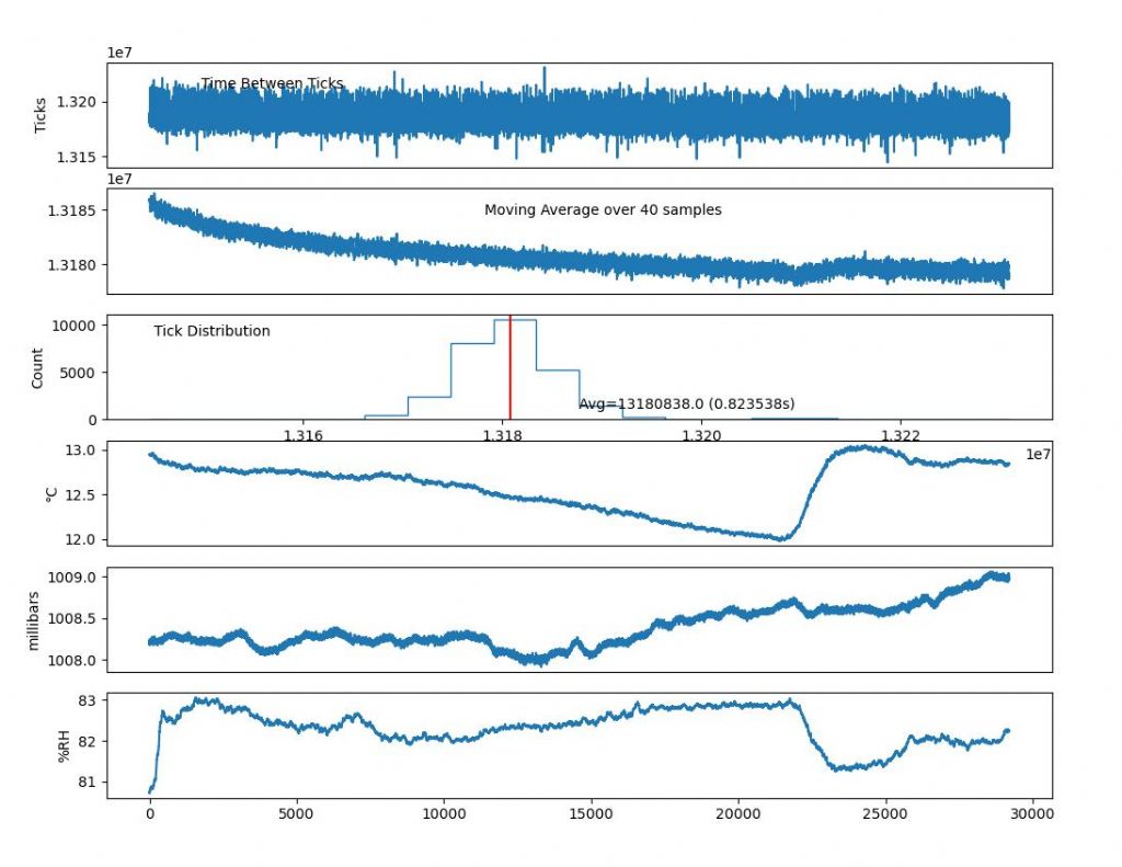
        Well, the clock is running again, and fixing the top to the columns properly seems to have fixed the strange double hump effect. The latest graph shows swing times peak at the average and fall off either side as they should.

        clock2911.jpg

        The adjusted pendulum is also swinging over a much smaller arc, and is only being impulsed once every 65 swings or so. Previously it was impulsed every 22 swings, implying Q is better now. It moves over such a small angle I'm worried it won't keep going!

        Possibly the double hump was caused by the suspension spring being lopsidedly loaded when the top was at an angle. Dunno.

        I'm going to leave it alone for a day or two to see if it settles.

        Dave

        #623242
        duncan webster 1
        Participant
          @duncanwebster1

          Giving it a kick every 65 swings means acceptance of a cyclic variation in period. I give my pendulum a much smaller nudge every swing unless it has exceeded its max swing, when the next nudge is missed out. I've never done detailed measurement, but intuitively I should have much less variation.

          Similarly, I've never quite understood vacuum chambers. Just seal it in an air tight space so that pressure and humidity don't change, much easier than maintaining a vacuum. I suppose vacuum will also reduce temperature fluctuation,but your carbon fibre rod has gone a long way to mitigating that.

          #623256
          Michael Gilligan
          Participant
            @michaelgilligan61133
            Posted by duncan webster on 01/12/2022 00:39:20:

            Giving it a kick every 65 swings means acceptance of a cyclic variation in period. I give my pendulum a much smaller nudge every swing unless it has exceeded its max swing, when the next nudge is missed out. I've never done detailed measurement, but intuitively I should have much less variation.

            .

            Good underlying logic there, Duncan yes

            Contrary to what ‘everyone’ gets taught about pendulums … Variation in Circular Error is a major ingredient in the recipe for bad timekeeping.

            MichaelG.

            #623265
            Peter Cook 6
            Participant
              @petercook6
              Posted by SillyOldDuffer on 29/11/2022 19:29:08:

              Possibly the double hump was caused by the suspension spring being lopsidedly loaded when the top was at an angle.

              Dave, the new behaviour persuades me that the double hump was an artefact of the pendulum rod & suspension spring behaving as a double pendulum. With the wider swing, the suspension spring stiffened up to the point where the carbon fibre rod would bend.

              With the new low arc, the forces never get to the point where the carbon fibre rod bends, so it acts as a rigid rod.

              #623269
              John Haine
              Participant
                @johnhaine32865
                Posted by Michael Gilligan on 01/12/2022 08:58:54:

                Posted by duncan webster on 01/12/2022 00:39:20:

                Giving it a kick every 65 swings means acceptance of a cyclic variation in period. I give my pendulum a much smaller nudge every swing unless it has exceeded its max swing, when the next nudge is missed out. I've never done detailed measurement, but intuitively I should have much less variation.

                .

                Good underlying logic there, Duncan yes

                Contrary to what ‘everyone’ gets taught about pendulums … Variation in Circular Error is a major ingredient in the recipe for bad timekeeping.

                MichaelG.

                Two points. First, it's true there will be a cyclic variation in period with the latter decreasing towards the next impulse. But, as everything else, that doesn't matter as long as the variation is always the same. Every impulse is also likely to cause a phase shift unless it's exactly symmetrical, for every type of escapement, but again as long as they are always the same it doesn't matter. As almost an extreme example, the grasshopper used in Clock B causes a lot of escapement deviation and the pendulum runs at an amplitude where there's a lot of circular deviation but the design balances these out with other factors as well to achieve great accuracy.

                Second, look at the Synchronome and the Shortt clocks – the latter especially is extremely accurate even though impulsed only every 30s.

                By the way there's a lot of confusion in nomenclature around "double pendulums". In physics the term usually applied to a system where there is a second bob hanging from the first and motion is frequently chaotic. There are "double pendulum" clocks that just have two pendulums hanging from supports where energy is coupled between them. Then a single pendulum can have two (or more) modes of oscillation – freqently the one you want which is side to side and another back-and-front which you don't The latter can be often be lower frequency because the effective length is a little longer, and energy can couple into it if the suspension doesn't allow the whole thing to hang vertical. The late Bob Matthys observed a bob that showed a very slight ellipticity in its motion – though it had a triple pivot suspension it didn't quite hang vertically because of stiction in the bracket trunnion.

                #623272
                Michael Gilligan
                Participant
                  @michaelgilligan61133

                  Apologies, John … I thought my underlining of Variation in would suffice

                  Clearly not; because, as you have pointed out :

                  that doesn't matter as long as the variation is always the same.

                  Tricky language, English !

                  Mea Culpa

                  MichaelG.

                  Edited By Michael Gilligan on 01/12/2022 12:09:51

                  #623279
                  SillyOldDuffer
                  Moderator
                    @sillyoldduffer
                    Posted by John Haine on 01/12/2022 11:30:28:

                    Posted by Michael Gilligan on 01/12/2022 08:58:54:

                    Posted by duncan webster on 01/12/2022 00:39:20:

                    Giving it a kick every 65 swings means acceptance of a cyclic variation in period. I give my pendulum a much smaller nudge every swing unless it has exceeded its max swing, when the next nudge is missed out. I've never done detailed measurement, but intuitively I should have much less variation.

                    .

                    Good underlying logic there, Duncan yes

                    Contrary to what ‘everyone’ gets taught about pendulums … Variation in Circular Error is a major ingredient in the recipe for bad timekeeping.

                    MichaelG.

                    Two points. First, it's true there will be a cyclic variation in period with the latter decreasing towards the next impulse. But, as everything else, that doesn't matter as long as the variation is always the same. Every impulse is also likely to cause a phase shift unless it's exactly symmetrical, for every type of escapement, but again as long as they are always the same it doesn't matter. As almost an extreme example, the grasshopper used in Clock B causes a lot of escapement deviation and the pendulum runs at an amplitude where there's a lot of circular deviation but the design balances these out with other factors as well to achieve great accuracy.

                    Second, look at the Synchronome and the Shortt clocks – the latter especially is extremely accurate even though impulsed only every 30s.

                    By the way there's a lot of confusion in nomenclature around "double pendulums". In physics the term usually applied to a system where there is a second bob hanging from the first and motion is frequently chaotic. There are "double pendulum" clocks that just have two pendulums hanging from supports where energy is coupled between them. Then a single pendulum can have two (or more) modes of oscillation – freqently the one you want which is side to side and another back-and-front which you don't The latter can be often be lower frequency because the effective length is a little longer, and energy can couple into it if the suspension doesn't allow the whole thing to hang vertical. The late Bob Matthys observed a bob that showed a very slight ellipticity in its motion – though it had a triple pivot suspension it didn't quite hang vertically because of stiction in the bracket trunnion.

                    These graphs confirm I think what's being said.

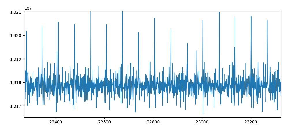
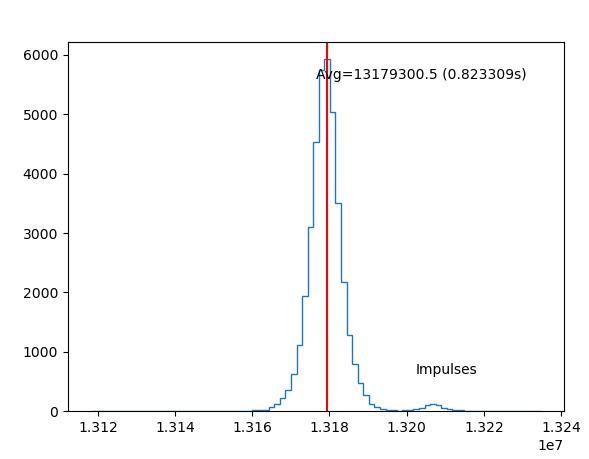
                    Zooming in on the ticks shows the impulse causes a significant disturbance:

                    impulsespikes.jpg

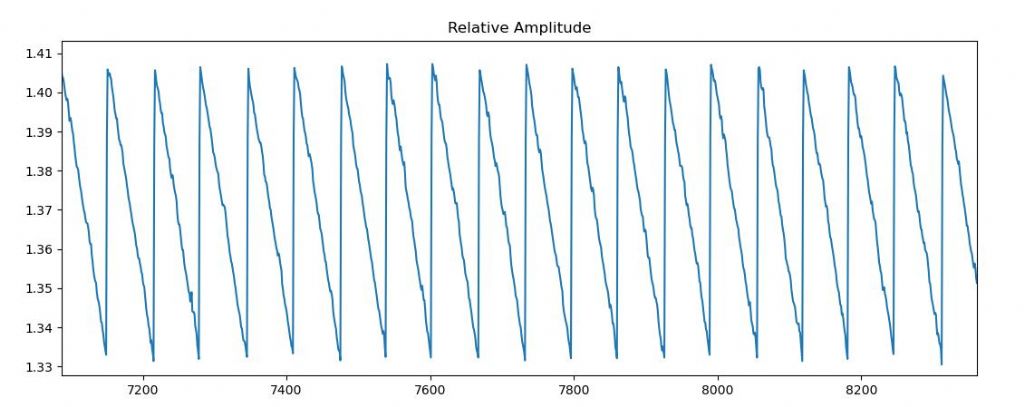
                    The same effect can be seen on the relative amplitude, which decays until kicked by the impulse, creating a saw-tooth:

                    relamp.jpg

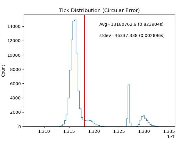
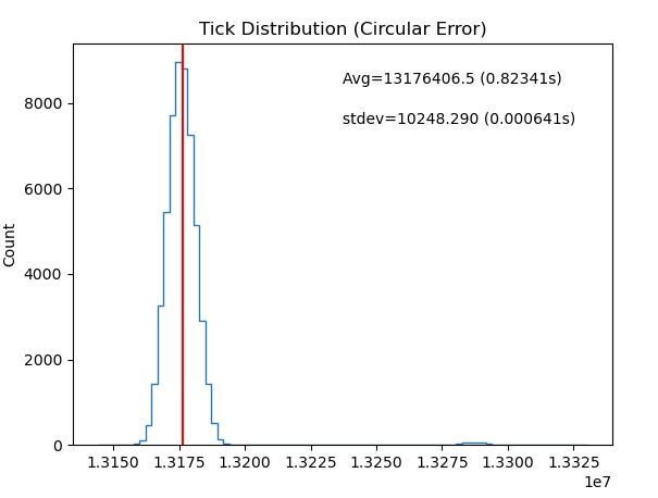
                    And again in the tick distribution, where a second peak shows impulsed ticks at about 1.321e7:

                    impulseca.jpg

                    So next step is to tell the software to reduce impulse length. It's set to 8uS*200 at the moment, 1.6mS, and I'll try halving it.

                    I think Peter's explanation of the earlier double hump distribution was correct. The pendulum rod is only 0.8mm in diameter, deliberately chosen in the Mk1 clock to be whippy. In line with John's comment that variation doesn't matter much as long as it's consistent, I hope the pendulum will keep eventually keep good time even though it's probably bending a little.

                    The amplitude data shows the impulse fires unnecessarily once in every 2000 beats or so. I suspect the software. One of the nice things about this clock is it has hardly anything mechanical for me to mess up; unfortunately I'm perfectly capable of getting the software wrong too! A quick fix might be to impulse only after relative amplitude has fallen below trigger point twice in succession.

                    Lunch first!

                    Dave


                    Edited By SillyOldDuffer on 01/12/2022 13:11:44

                    #623281
                    Michael Gilligan
                    Participant
                      @michaelgilligan61133

                      Well done, Dave … all nicely illustrated yes

                      The ‘Holy Grail’ of a free-pendulum might be a tiny spot on the horizon, but you are heading in the right direction.

                      MichaelG.

                      .

                      P.S. __ You wrote:

                      The pendulum rod is only 0.8mm in diameter, deliberately chosen in the Mk1 clock to be whippy. In line with John's comment that variation doesn't matter much as long as it's consistent, I hope the pendulum will keep eventually keep good time even though it's probably bending a little.

                      That ^^^ was exactly the point I was trying to make when I praised Duncan’s approach … If he is detecting when the pendulum has just [infinitesimally] swung too far, and he then skips an impulse, he is homing-in on minimal disturbance.

                      The more critically he can detect that over-swing, the better. 

                      Edited By Michael Gilligan on 01/12/2022 13:32:49

                      #623296
                      duncan webster 1
                      Participant
                        @duncanwebster1

                        According to Mr Hooke there is no lower limit of force which causes no deflection. If I walked over the Forth bridge ir would deflect, but you'd struggle to measure it. It can get a bit more complicated with things like prestressed concrete but that need not concern us

                        #623305
                        Michael Gilligan
                        Participant
                          @michaelgilligan61133

                          A very wise man, Mr Hooke star

                          I sometimes wonder what impressive argument he would offer against our modern reliance upon Finite Elements.

                          MichaelG.

                          #623309
                          duncan webster 1
                          Participant
                            @duncanwebster1

                            I don't think he would, FE relies on Hooke's law until it gets into the plastic region then it gets really difficult.

                            #623313
                            Michael Gilligan
                            Participant
                              @michaelgilligan61133
                              Posted by duncan webster on 01/12/2022 19:34:53:

                              I don't think he would, FE relies on Hooke's law until it gets into the plastic region then it gets really difficult.

                              .

                              You seem to have missed my point, Duncan … it was the finite-ness of the elements that I presumed Hooke might object to.

                              MichaelG.

                              #623321
                              SillyOldDuffer
                              Moderator
                                @sillyoldduffer
                                Posted by John Haine on 28/11/2022 16:47:09:

                                One thing that occurs to me is that the suspension seems to permit movement in only one direction. If the axis of the upper part is not dead vertical and in line with the rod axis, the spring may be buckling slightly which could couple energy to other modes.

                                Thus the spring tension is along its axis. As well as possible buckling, maybe your rather narrow spring allows some twisting?

                                I hadn't thought of that but it makes sense. Thanks for pointing it out. The clock has no means of levelling other than shimming the feet, making it easy to twist the spring. Back to the drawing board.

                                Dave

                                PS What did they go back to before they had drawing boards?

                                #623324
                                Michael Gilligan
                                Participant
                                  @michaelgilligan61133

                                  Posted by SillyOldDuffer on 01/12/2022 22:01:21:

                                  […]

                                  PS What did they go back to before they had drawing boards?

                                  .

                                  Scratches and paint-splatter on the walls of the cave

                                  MichaelG.

                                  #623416
                                  SillyOldDuffer
                                  Moderator
                                    @sillyoldduffer

                                    This morning's results are disappointing even though the time-keeping was closer to reality: 36 seconds slow after 22 hours. The run was intended to test reduced impulses, 0.48mS rather than 1.6mS.

                                    Sadly the Tick Time graph shows bursts of wild pendulum behaviour. Not good.

                                    clock12ticks.jpg

                                    And the Tick distribution shows three modes, which skew the average well away from the mode, and a high standard deviation of nearly 3mS, yuk:

                                    clock12dist.jpg

                                    I think the fault is due to moving the clock physically to apply software upgrades. Not much stops the bob bouncing about in any direction. As already pointed out my suspension design is flawed, and I think mechanical issues are more likely to explain major misbehaviour than me tweaking the software:

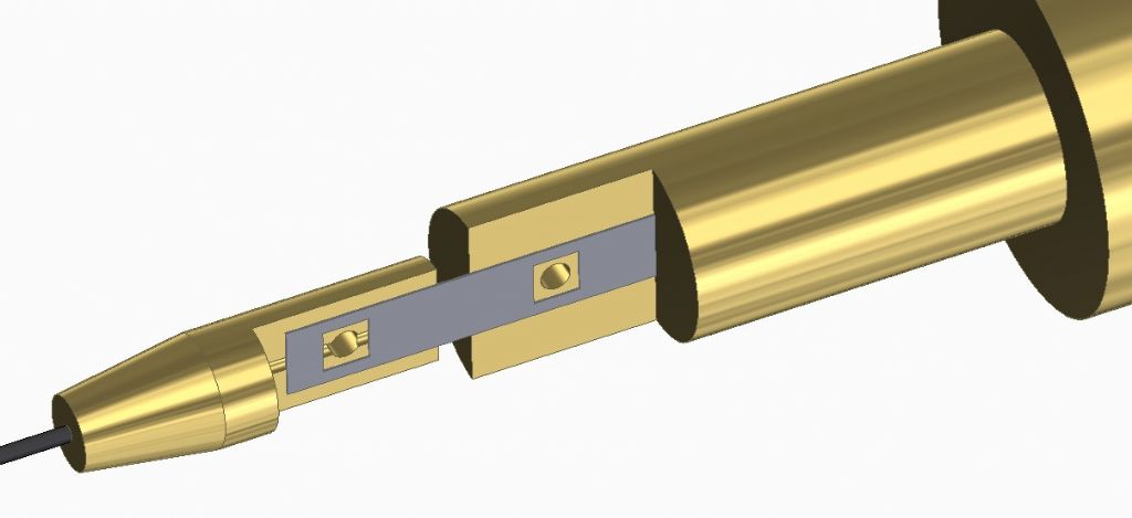
                                    pendulmsprwocheeks.jpg

                                    • Nothing stops the whole spring moving right/left other than the clamp force. Better I think to solder it as well.
                                    • The spring will buckle unless the clock is exactly vertical. An arrangement allowing the suspension to tilt is needed to prevent this. (See John's photo earlier in the thread.)
                                    • As the pendulum is delicate, some way of stopping it flying about during transit is needed
                                    • Better to update the clock's software without physically moving it.

                                    Next step is to make a better suspension.

                                    Meanwhile, how the clock is meant to work may be of interest.

                                    Assuming a low error pendulum, the idea is to count the total number of ticks timed accurately over several days by NTP or GPS. Air pressure, temperature and relative humidity are also logged, so the clock's environment is available.

                                    By statistical analysis this data gives the pendulum's average period and identifies any correlation between period and environmental changes. And as correlations are measurable, it's possible to derive correction formulae, that can be applied on the fly by the clock's microcontroller to the average period.

                                    Thus, when the clock is free-standing, and counting beats, its gear train function takes the average period and adjusts the number to what it should be given the current measured temperature, pressure and humidity levels. This replaces physical temperature compensation methods, and the rather complex mechanism needed to correct a pendulum for barometric change. In addition, the clock is intended to run in a vacuum, hopefully making the software tweaks tiny.

                                    All this depends on me making a decent pendulum! So far no coconut…

                                    Dave

                                    #623424
                                    John Haine
                                    Participant
                                      @johnhaine32865

                                      How are you sensing Dave? I have seen some wild behaviour using opto interrupters due to ambient light.

                                      Edited By John Haine on 03/12/2022 13:05:04

                                      #623444
                                      SillyOldDuffer
                                      Moderator
                                        @sillyoldduffer
                                        Posted by John Haine on 03/12/2022 13:04:34:

                                        How are you sensing Dave? I have seen some wild behaviour using opto interrupters due to ambient light.

                                        Here's a photo:

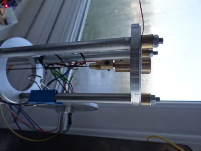
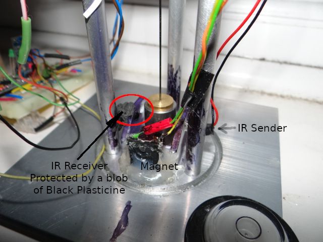
                                        dsc06650.jpg

                                        The black and blue felt-tip pen ink marks are the remains of colouring in to reduce reflections off the steel bob, aluminium frame and shiny white plastic innards. I dropped the current to the IR sender with a 68 ohm resistor for the same reason.

                                        To protect the IR receiver from ambient light, the back of the sensor is embedded in black plasticine. Strong ambient light alters the sensitivity of the sensor unless it's protected.

                                        I didn't think ambient light was likely because the weather here is a foggy gloom, and much of the run was after dark. However, taking the photo did me a favour! Moving in for a close up I heard a tiny click, caused by the bob hitting the magnet. No wonder the tick timings are bad.

                                        I'm going to restart the clock with a smaller impulse. Luckily, I reprogrammed the microcontroller last time to take commands that reset the nominal period, impulse threshold and impulse length without physically touching the clock: moving it is definitely bad.

                                        The way I measure 'amplitude' is under review. Period is the time between beam blocked events. I also measure the time taken by the bob to overfly the beam – how long the beam is blocked – and use the ratio "Beam Blocked" to Period to indicate relative amplitude. Looking at the code after Peter's comments I'm not sure the way I implemented this is correct.

                                        Thanks again!

                                        Dave

                                        #623451
                                        duncan webster 1
                                        Participant
                                          @duncanwebster1

                                          It's been said before, but you'd be a lot better having the electromagnet below the pendulum so it impulses close to mid-point of swing (Science of Clocks and Watches explains why) and no chance of hitting the bob. The only down-side is it won't self start. I have a crazy scheme for a linear motor impulse so that it could be at mid point but would also self start. This will never get beyond a whimsy, far too complicated for little benefit

                                          I've had no problems with ambient light and slotted opto switches, but it is positioned out of direct sun

                                          #623465
                                          John Haine
                                          Participant
                                            @johnhaine32865

                                            My current build is centre impulsed and should self start.

                                            #623467
                                            SillyOldDuffer
                                            Moderator
                                              @sillyoldduffer
                                              Posted by duncan webster on 03/12/2022 17:50:07:

                                              It's been said before, but you'd be a lot better having the electromagnet below the pendulum so it impulses close to mid-point of swing (Science of Clocks and Watches explains why) and no chance of hitting the bob. The only down-side is it won't self start. …

                                              Maybe! The side-on magnet is an experimental feature. With a mechanical system, it's definitely important to minimise the clunk by impulsing when the bob is travelling at maximum speed. And doing the same with an electromagnet would do no harm.

                                              However, when my side-on magnet fires, the bob still be distant from the electromagnet, making the impulse effect rather soft, only gradually accelerating the bob towards the magnet. I hope! And then the pulse is timed to switch off before the bob gets anywhere near it. The idea is to have the bob gain energy by briefly balancing out gravity with a minimal magnetic pulse. Thus it flies a little higher before gravity dominates again, and the impulse is gentle. The data I'm getting suggests it's possible to adjust the impulse so that it doesn't disturb the pendulum. Also, the beam is broken shortly after after BDC when the bob is still travelling fairly fast.

                                              The idea is unproven : it seems only I've tried tightly controlling the timing and power of a side pulse, and my data is noisy for other reasons. Any brave volunteers willing to try my approach with a big well-made pendulum?

                                              A big advantage is the clock is self-starting, which becomes vital when the pendulum is sealed inside a vacuum chamber.

                                              Dave

                                              #623483
                                              Martin Kyte
                                              Participant
                                                @martinkyte99762

                                                Nothing to stop you having a starting solenoid at the side and then switching to one at mid swing once you have movement.
                                                regards Martin

                                                #623493
                                                duncan webster 1
                                                Participant
                                                  @duncanwebster1
                                                  Posted by John Haine on 03/12/2022 19:35:48:

                                                  My current build is centre impulsed and should self start.

                                                  Like this Brille? If not then tell all!

                                                  #623541
                                                  SillyOldDuffer
                                                  Moderator
                                                    @sillyoldduffer

                                                    Mixed result this morning, With reduced impulse, the pendulum is still being bumped:

                                                    clock13ticks.jpg

                                                    But the tick distribution is better:

                                                    clock13ce.jpg

                                                    Despite the impulse bumps, this is the best run yet: my clock is 0.792secs fast after 12 hours 21 minutes.

                                                    Gut feel is the impulse is much too strong, so I'll reduce it. Fingers crossed, the circular error will fall again.

                                                    Dave

                                                    #623543
                                                    John Haine
                                                    Participant
                                                      @johnhaine32865
                                                      Posted by duncan webster on 03/12/2022 23:09:15:

                                                      Posted by John Haine on 03/12/2022 19:35:48:

                                                      My current build is centre impulsed and should self start.

                                                      Like this Brille? If not then tell all!

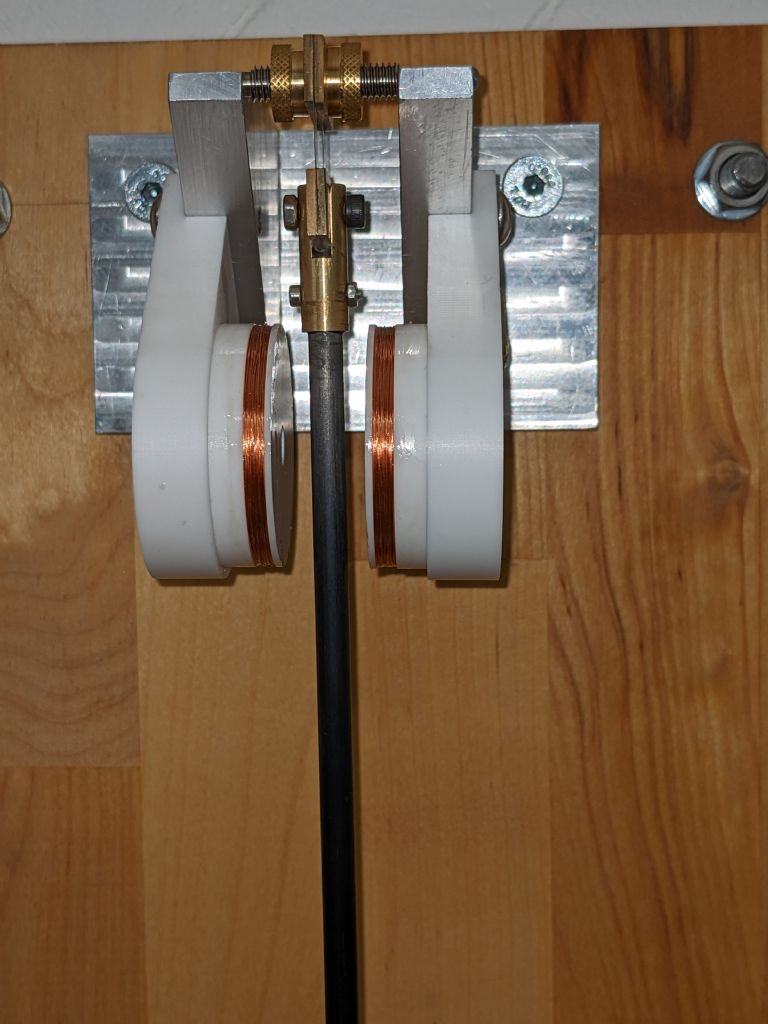
                                                      pxl_20221119_175738639.jpg

                                                      Hiding inside the 6mm CF tube which forms the rod is a 13 x 3mm neodymium bar magnet which is transverse coaxial with the Helmholtz coils either side of it. When the coils are driven the magnet tries to line up with the field, exerting a torque on the pendulum. Sensing is by a slotted vane on the bottom of the bob. The pendulum should be startable by sending alternating current pulses to the coils at 0.5Hz. The scheme certainly works with the bob removed, but the Q is such that it will take nearly 2 hours to reach working amplitude with it attached! This scheme made possible by using carbon fibre tube, it wouldn't work with a steel rod.

                                                    Viewing 25 posts - 26 through 50 (of 562 total)
                                                    • Please log in to reply to this topic. Registering is free and easy using the links on the menu at the top of this page.

                                                    Advert

                                                    Latest Replies

                                                    Viewing 25 topics - 1 through 25 (of 25 total)
                                                    Viewing 25 topics - 1 through 25 (of 25 total)

                                                    View full reply list.

                                                    Advert

                                                    Newsletter Sign-up