Experimental Pendulum Clock

Advert

Experimental Pendulum Clock

Home Forums Clocks and Scientific Instruments Experimental Pendulum Clock

Viewing 25 posts - 451 through 475 (of 562 total)
  • Author
    Posts
  • #633149
    Joseph Noci 1
    Participant
      @josephnoci1
      Posted by Martin Kyte on 12/02/2023 16:02:00:

      and you should really pull at least one input of the other gates low. Noise on undefined inputs causes the outputs to switch putting noise on the power rails.

      OK it’s a nicety but general good practice.

      regards Martin

      With TTL it is 'not' strictly needed to tie inputs hi or lo ( TTL, HSTTL, etc) – the totem inputs settle lo, so you can get away with it, but Martin's 'should' is sound advice – they may settle lo but invariable end up drawing more gate current. Don't leave mos(Cmos, Hmos, etc) inputs floating though..

      As a proficient hacker, when one gate is used as a buffer, on breadboard I simply blob some solder on pins 1 and 2, then 3,4,5 and 10,11,12, use pin 1 or 2 as in, pin 3 or 6 as out, and blob 8 to 9 and connect them to ground(7).

      Edited By Joseph Noci 1 on 12/02/2023 17:12:39

      Advert
      #633321
      SillyOldDuffer
      Moderator
        @sillyoldduffer

        Not much progress. Joe's fix worked perfectly but my only 7490 divider chip is dead, probably because I wired it up back to front in an earlier fiasco. Had to order another one, so can't finish the OCXO.

        Clock still misbehaving with interesting features. (Yes I know I should get out more!)

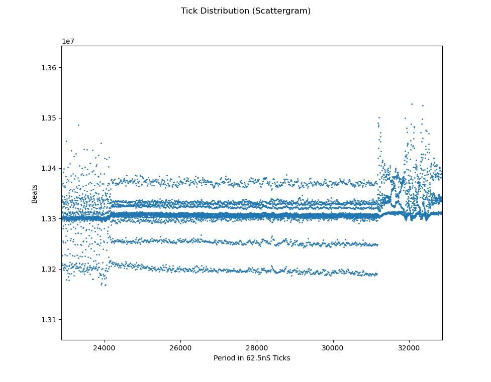
        1302tickdistro.jpeg

        Broadly, depending on impulse power, the pendulum vibrates in at least three different modes, only one of which is wanted – the nice tight line marked STABLE in green above. The pendulum doesn't deviate much, unlike in the red UNSTABLE areas, where the pendulum bounces all over the place.

        The zone I can't explain is ringed in purple, because it shows the pendulum vibrating in one of several frequencies, making a quantum leap between them. Zooming in, I think I see at least 11 separate traces:

        1302multfreq.jpeg

        Any ideas what could cause several close but different discrete vibrations. Multi-frequency mode ended abruptly when I reduced the impulse slightly.

        Another quirk is the clock keeps better time when the pendulum is in the unstable zone:

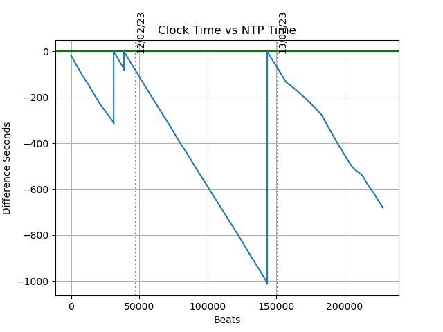
        1302drift.jpeg

        The drift rate on the 12th, when the pendulum was being distinctly over-impulsed, is delightfully constant, meaning it can easily be compensated to stay closely aligned with NTP time. Echoes a comment in Grimthorpe about early clockmakers setting up so the clock dominates the pendulum. In comparison, after the impulse was reduced, causing the pendulum to stabliise, the drift rate on the 13th is kinky! The log shows low impulse power on the 13th starts causing beam break misreads = the pendulum isn't swinging quite far enough.

        Confirms the way I modified the sensor in hope of sharpening the beam didn't work, and – woe, woe and thrice woe – the clock is worse than before I 'fixed' it. Oh bum.

        Never mind, I've started to plan a major hardware upgrade. I'll share the list later for comment.

        Dave


        Edited By SillyOldDuffer on 13/02/2023 19:03:22

        #633327
        Michael Gilligan
        Participant
          @michaelgilligan61133

          This is a grossly simplistic analysis, but we have to start somewhere:

          Mechanical systems do switch from one resonant mode to another, especially if the frequencies of the different modes are either close, or harmonically related. … What you appear to have is multiple modes, none of which is strongly dominant in terms of Q.

          That’s an impressive achievement, but far from ideal !!

          I suspect [but it’s only a guess] that increasing the mass of your pendulum bob might help. … But it may also be that there are intrusive torsional modes, which that would do very little to reduce.

          In truth, I think you need to get the suspension improved first, and see what difference that makes.

          MichaelG.

          Edited By Michael Gilligan on 13/02/2023 19:30:55

          #633333
          SillyOldDuffer
          Moderator
            @sillyoldduffer
            Posted by Michael Gilligan on 13/02/2023 19:29:48:…

            I suspect [but it’s only a guess] that increasing the mass of your pendulum bob might help. … But it may also be that there are intrusive torsional modes, which that would do very little to reduce.

            In truth, I think you need to get the suspension improved first, and see what difference that makes.

            Good advice, thanks. My bob is tiny compared with most, under 30g from memory, and it's suspended on a 1mm diameter carbon fibre rod, twang! More weight would help, and I'm thinking Tungsten putty in a steel sleeve.

            I agree about fixing the suspension first, my design is naive and the spring is all too likely to twist unless the clock is perfectly aligned, which is hard to do. I'm not proud of the suspension.

            Dave

            #633339
            duncan webster 1
            Participant
              @duncanwebster1

              Tungsten putty is 10g/cc, but according to interweb it doesn't set, which might be a problem. Steel is 7.8 g/cc, is it worth the effort to go to putty. I've been advised against lead as it changes shape over the years. What would be ideal is tungsten/copper alloy, but it's expensive

              #633340
              Martin Kyte
              Participant
                @martinkyte99762
                Posted by duncan webster on 13/02/2023 20:46:01:

                Tungsten putty is 10g/cc, but according to interweb it doesn't set, which might be a problem. Steel is 7.8 g/cc, is it worth the effort to go to putty. I've been advised against lead as it changes shape over the years. What would be ideal is tungsten/copper alloy, but it's expensive

                Regarding the shape shifting lead does that relate to a cast lead bob or a brass cased lead filled version.?

                I’d love to hear some detail on the problems of using lead.

                regards in anticipation

                Martin

                #633345
                duncan webster 1
                Participant
                  @duncanwebster1

                  I don't have actual experience is the answer, I was advised by a Fellow of the BHI. I can see it happening with a lump of lead, especially under the support, but if it is confined in a shroud of steel or brass it's got nowhere to go. However my experience of casting lead into grinding wheels (don't ask!) is that it shrinks away from the mould. If it's fairly thin then hitting it axially makes it swell sideways and fill the space. Another possibility is a mix of tungsten powder and potting resin, but again no actual experience.

                  My clock started with a thin stainless tube with close fitting machined discs of lead, it now has a mild steel bar inside the SS tube

                  Edited By duncan webster on 13/02/2023 21:56:56

                  #633346
                  Tony Jeffree
                  Participant
                    @tonyjeffree56510

                    Is potting resin likely to be any more dimensionally stable over time than lead…?

                    #633347
                    Martin Kyte
                    Participant
                      @martinkyte99762

                      Thanks for the reply Duncan. I’ve done a few clock weights in brass jackets and unless the damp newspaper trick is employed the lead sticks to the brass case and shrinkage occurs from the top. My Synchronome bob was lead filled. I can’t remember exactly how I did it now but it has a brass tube soldered into the bottom cap and then lead filled in a similar way. Again if I remember the lead seemed tight to the tube and the jacket with all the shrinkage taken from the top surface.
                      As an aside the central tube is bored out from the bottom slightly larger to create a step half way up. The rod passes through the top portion and then through a separate tube inserted into the bob tube. The end of the rod is threaded for an adjusting nut so the bob is supported in the middle and can expand both ways. Small washers can be added to temperature compensate for the bottom suspension the mechanism of which escapes me just now.

                      Regards Martin

                      #633348
                      duncan webster 1
                      Participant
                        @duncanwebster1
                        Posted by Tony Jeffree on 13/02/2023 22:10:52:

                        Is potting resin likely to be any more dimensionally stable over time than lead…?

                        Dunno, but if it's inside a brass or steel sleeve it can't sag sideways. Perhaps the powder might migrate slowly down through the resin. I kept it simple. Of course the resin might shrink over time.

                        #633350
                        Tony Jeffree
                        Participant
                          @tonyjeffree56510
                          Posted by duncan webster on 13/02/2023 22:44:42:

                          Posted by Tony Jeffree on 13/02/2023 22:10:52:

                          Is potting resin likely to be any more dimensionally stable over time than lead…?

                          Dunno, but if it's inside a brass or steel sleeve it can't sag sideways. Perhaps the powder might migrate slowly down through the resin. I kept it simple. Of course the resin might shrink over time.

                          True. As per Martin K's comment above, mine is brass sleeve with end caps and central steel tube, completely filled with lead, so not convinced the lead has anywhere significant to go to.

                          #633389
                          SillyOldDuffer
                          Moderator
                            @sillyoldduffer
                            Posted by Tony Jeffree on 13/02/2023 23:01:50:

                            Posted by duncan webster on 13/02/2023 22:44:42:

                            Posted by Tony Jeffree on 13/02/2023 22:10:52:

                            Is potting resin likely to be any more dimensionally stable over time than lead…?

                            Dunno, but if it's inside a brass or steel sleeve it can't sag sideways. Perhaps the powder might migrate slowly down through the resin. I kept it simple. Of course the resin might shrink over time.

                            True. As per Martin K's comment above, mine is brass sleeve with end caps and central steel tube, completely filled with lead, so not convinced the lead has anywhere significant to go to.

                            Much depends on how obsessive one is about accuracy!

                            Lead has a high coefficient of thermal expansion – about 6 times greater than mild-steel. So, as the bob forms part of the length of the pendulum, a lead bobbed clock will need more temperature compensation that one with mild-steel.

                            Lead is plastic, which might cause period to alter as the metal settles, though I'd expect the effect to be small, perhaps taking years to appear. I worried it might move inside the canister, but remembered Mercury was for a long time the de-facto best bob material for Regulator Clocks, where its thermal expansion was arranged to provide temperature compensation. No-one mentions the liquid sloshing about inside the bob as being a problem!

                            Choosing the a bob material is a compromise. Lead's high-density, chemical stability and availability are desirable properties but thermal expansion is awkward. Mild-steel is reasonably dense, magnetic (important in my case), readily available and has low thermal expansion, but it's highly chemically unstable – liable to rust away over a few years. Tungsten is high-density, chemically stable and low expansion, but it's hard to source and work with. Aluminium and Magnesium are too light. Brass has high thermal expansion – a poor choice. Stainless is a possibility.

                            There's a danger of becoming a 'Time Nut' – I could go on, and on, and on about bobs. What's the best shape?

                            smiley

                            Dave

                            #633394
                            Michael Gilligan
                            Participant
                              @michaelgilligan61133

                              With the greatest respect to all concerned … recent posts look like ‘displacement activity’

                              Dave has an issue with multi-mode vibration; which needs sorting if his project is to succeed.

                              The medium to long term stability of bob-materials is always ‘interesting’ but surely not very relevant to a test which will probably take less than a week to produce useful results.

                              MichaelG.

                              #633409
                              SillyOldDuffer
                              Moderator
                                @sillyoldduffer
                                Posted by Michael Gilligan on 14/02/2023 11:06:23:

                                With the greatest respect to all concerned … recent posts look like ‘displacement activity’

                                Dave has an issue with multi-mode vibration; which needs sorting if his project is to succeed.

                                The medium to long term stability of bob-materials is always ‘interesting’ but surely not very relevant to a test which will probably take less than a week to produce useful results.

                                MichaelG.

                                True, but I'm not averse to a bit of wandering and cross-fertilisation! I've been thinking of trying a denser bob density in connection with my vibration problems, so what people have found with Lead and other materials is of interest. I'm inclining towards Tungsten Putty at the moment because it can be squeezed into a steel container to make a dense magnetic bob, but not thought it through.

                                Not much time for clocks at the moment, rushing about looking after an unwell mother and yesterday taking a broken cat to the vet cost me £81!

                                Dave

                                #633412
                                duncan webster 1
                                Participant
                                  @duncanwebster1

                                  You could have got a new cat fot less than that😜

                                  #633423
                                  Joseph Noci 1
                                  Participant
                                    @josephnoci1

                                    There's a danger of becoming a 'Time Nut' – I could go on, and on, and on about bobs. What's the best shape?

                                    smiley

                                    Dave

                                    No Danger at all – You ARE already one…It is highly contagious. I already am one, but all these swinging pendula have now set me off…

                                    I want to try from a different view though – I have a good GPSDO 10MHz signal source with outputs down to one sec. It uses a TI chip as digital Time Interval detector to determine the variation between the GPS 1pps and the disciplined oscillator, down to 2 or so picosec.

                                    So, I am going to try discipline the pendulum using the GPSDO as reference as there is then no jitter on the Reference Clock. Another of the TI chip will be fed the 10MHz ref, and the gate will be the pendulum swing. The error count will represent pendulum error in the same way that the GPSDO TI chip gives the error between GPS 1pps and the 10MHz osc.

                                    So what, you say – you cheated and now have a pendulum locked to 1pps…

                                    True, but I will record Temp, humidity AND the error signal, ie, the time correction applied to the pendulum pulse and try work back from that to derive correction curve for the pendulum as stand alone…

                                    Or I may hide in shame…

                                    #633425
                                    Joseph Noci 1
                                    Participant
                                      @josephnoci1
                                      Posted by duncan webster on 14/02/2023 13:25:19:

                                      You could have got a new cat fot less than that😜

                                      Mmmm – Flay that man…

                                      #633429
                                      duncan webster 1
                                      Participant
                                        @duncanwebster1
                                        Posted by SillyOldDuffer on 14/02/2023 12:56:50:

                                        Posted by Michael Gilligan on 14/02/2023 11:06:23:

                                        With the greatest respect to all concerned … recent posts look like ‘displacement activity’

                                        Dave has an issue with multi-mode vibration; which needs sorting if his project is to succeed.

                                        The medium to long term stability of bob-materials is always ‘interesting’ but surely not very relevant to a test which will probably take less than a week to produce useful results.

                                        MichaelG.

                                        True, but I'm not averse to a bit of wandering and cross-fertilisation! I've been thinking of trying a denser bob density in connection with my vibration problems, so what people have found with Lead and other materials is of interest. I'm inclining towards Tungsten Putty at the moment because it can be squeezed into a steel container to make a dense magnetic bob, but not thought it through.

                                        Not much time for clocks at the moment, rushing about looking after an unwell mother and yesterday taking a broken cat to the vet cost me £81!

                                        Dave

                                        Have a day out with a metal detector at the army's Lulworth range, must be loads of bits of tungsten lying around.

                                        #633430
                                        Nealeb
                                        Participant
                                          @nealeb

                                          …or depleted uranium…

                                          #633431
                                          SillyOldDuffer
                                          Moderator
                                            @sillyoldduffer
                                            Posted by Joseph Noci 1 on 14/02/2023 14:44:22:

                                            There's a danger of becoming a 'Time Nut' – I could go on, and on, and on about bobs. What's the best shape?

                                            smiley

                                            Dave

                                            I want to try from a different view though – I have a good GPSDO 10MHz signal source with outputs down to one sec. It uses a TI chip as digital Time Interval detector to determine the variation between the GPS 1pps and the disciplined oscillator, down to 2 or so picosec.

                                            So, I am going to try discipline the pendulum using the GPSDO as reference as there is then no jitter on the Reference Clock. Another of the TI chip will be fed the 10MHz ref, and the gate will be the pendulum swing. The error count will represent pendulum error in the same way that the GPSDO TI chip gives the error between GPS 1pps and the 10MHz osc.

                                            So what, you say – you cheated and now have a pendulum locked to 1pps…

                                            True, but I will record Temp, humidity AND the error signal, ie, the time correction applied to the pendulum pulse and try work back from that to derive correction curve for the pendulum as stand alone…

                                            Or I may hide in shame…

                                            Like the sound of that! Which TI chip gets down to 2 picoseconds and how does it work? I want one!

                                            Dave

                                            #633437
                                            Joseph Noci 1
                                            Participant
                                              @josephnoci1
                                              Posted by SillyOldDuffer on 14/02/2023 15:33:40:

                                              Posted by Joseph Noci 1 on 14/02/2023 14:44:22:

                                              There's a danger of becoming a 'Time Nut' – I could go on, and on, and on about bobs. What's the best shape?

                                              smiley

                                              Dave

                                              I want to try from a different view though – I have a good GPSDO 10MHz signal source with outputs down to one sec. It uses a TI chip as digital Time Interval detector to determine the variation between the GPS 1pps and the disciplined oscillator, down to 2 or so picosec.

                                              Like the sound of that! Which TI chip gets down to 2 picoseconds and how does it work? I want one!

                                              Dave

                                              Sorry, did not hit the '0' key hard enough…not 2 but 20ps or so…Chip is TI's TDC7200, 2 modes gives one of 12-500ns range, or 250ns to 8ms. Resolution is typ 55ps, interpolatable to half that, and standard dev. of 35ps. It is fairly common in more complex DIY GPSDO's and there are a lot of circuits and example code if you dig a bit.

                                              Digikey…also Mouser UK has stock – they also have a useful eval-board but at a stupid price…

                                              It uses a fast internal ring counter mechanism, which is temp sensitive, but is easily and quickly calibrated against the reference clock.

                                              #633559
                                              Joseph Noci 1
                                              Participant
                                                @josephnoci1

                                                Dave ( and the other swingers..) ,

                                                There is a much easier way to obtain a very stable clock reference, and even very accurate if you are happy to play some games…

                                                With any of the UBLOX neo-7/9 or M8N series ( and, I am sure, most of the other low cost UBLOX devices), you can, using their U-Center software, set the 1pps output to be almost any frequency you want. This works with any UBLOX that has FLASH and a TCXO.

                                                The resulting clock has traits and compromises – most of these GPS's use a 26MHz or a 48MHz internal reference, from which this 1PPS is derived and disciplined. We are all familiar with the jitter on the 1PPS. Likewise there can be jitter on the new programmed clock as well, but normally only when the desired frequency is not a power of 2 divisor from the ref clock. So, a 10MHz desired clock will have jitter regardless of the internal ref clock freq ( 26 or 48MHz). The nominal frequency is a very accurate 10MHz, but it has jitter. It is also VERY stable (locked to the constellation). The kind of jitter is similar to when you wire a 7490 in div2 then div5 mode – the div 5 is not a power of 2, so the output waveform has jitter. Wiring it div5 then div2 gives a clean, no jitter waveform.

                                                So, set the UBLOX output to be 12MHz, a clean and stable, jitter free clock output if ref clock is 48MHz and use that as your clock source to the Time Interval counter. If you use a 16bit counter, fed by the direct 48MHz output clock, for example, gated by the pendulum swing, you can capture the counter overflow and log the deviation in that number – the resolution then is 20ns….


                                                Edited By Joseph Noci 1 on 15/02/2023 11:57:09

                                                #633568
                                                John Haine
                                                Participant
                                                  @johnhaine32865

                                                  And since the picPET can be clocked at up to 20 MHz this will work beautifully but give a slightly smaller time increment, which isn't a problem. Nice!

                                                  #633572
                                                  Joseph Noci 1
                                                  Participant
                                                    @josephnoci1
                                                    Posted by John Haine on 15/02/2023 12:36:20:

                                                    And since the picPET can be clocked at up to 20 MHz this will work beautifully but give a slightly smaller time increment, which isn't a problem. Nice!

                                                    You may have to experiment a little – I last messed with this in 2020 or so, and the GPS's have moved on a little since then – The are still a few unknowns in the exact internal workings on these module – for example, 8MHz is a clean, solid jitter free clock as well, but certainly not a power of 2 divisor for 26 or 48…All the 1PPS programmable output GPS's seem to use an NCO ( numerically controlled osc, like a DDS somehow) and the quality of result depends on its features. The -T ( or timing version) GPS's are much better in signal integrity and jitter as well, but costly.

                                                    I guess you could design the pendulum to be a 1.2sec pendulum and measure with the 8MHz ref clock and define a whole new time 1 seconds standard…

                                                    edit – jitter not jotter..

                                                    Added note – 

                                                    By NO means will this be accurate or stable enough to be in the 10 minus 10 or 11 / 10sec domain, ie, into reasonable GPSDO domain, but it is quite good enough for pendulum assessment!

                                                    Edited By Joseph Noci 1 on 15/02/2023 13:02:31

                                                    #633581
                                                    SillyOldDuffer
                                                    Moderator
                                                      @sillyoldduffer
                                                      Posted by Joseph Noci 1 on 15/02/2023 11:55:02:

                                                      Dave ( and the other swingers..) ,

                                                      There is a much easier way to obtain a very stable clock reference, and even very accurate if you are happy to play some games…

                                                      Thanks for that, I've ordered one!

                                                      It breaks with my determination to keep the electronics Arduino compatible, but now I'm thinking of porting my clock to a Nucleo and using it's faster Timer/Counters with a UBLOX to get better resolution and accuracy than is possible with an AVR microcontroller clocked at 16MHz. Won't do it until the physical clock has been upgraded because the need to make mechanical improvements is becoming urgent.

                                                      Dave

                                                    Viewing 25 posts - 451 through 475 (of 562 total)
                                                    • Please log in to reply to this topic. Registering is free and easy using the links on the menu at the top of this page.

                                                    Advert

                                                    Latest Replies

                                                    Viewing 25 topics - 1 through 25 (of 25 total)
                                                    Viewing 25 topics - 1 through 25 (of 25 total)

                                                    View full reply list.

                                                    Advert

                                                    Newsletter Sign-up