Higher temperature = lower density = less drag. For a fixed impulse that gives higher amplitude. However if that were the case I'd expect a similar correlation of amplitude with pressure.
It's very difficult to measure the amplitude. Using an opto-interrupter, for example, will only tell you if the amplitude is equal or greater than its position, or lesser, but it won't actually "measure" the amplitude other than in that binary sense.
Computing amplitude from the velocity at BDC is a practical approach to gain insight into amplitude-related effects. It's not the same as actually measuring amplitude, but it should be correlated with it well enough to be useful.
Using an opto-interrupter, for example, will only tell you if the amplitude is equal or greater than its position, or lesser, but it won't actually "measure" the amplitude other than in that binary sense
Logging the duration of the interruption gets you a measure of the increase or decrease in amplitude.
Bit the bullet, and as expected my clock is a suitable case for treatment!
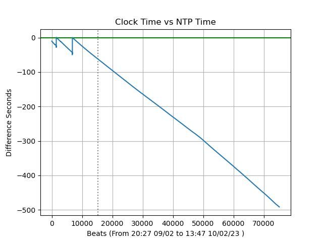
Glad tidings first: no bad sensor readings and drift looks constant (ie. easy to compensate), though there may be a knee at beat 50000:
Next the headaches!
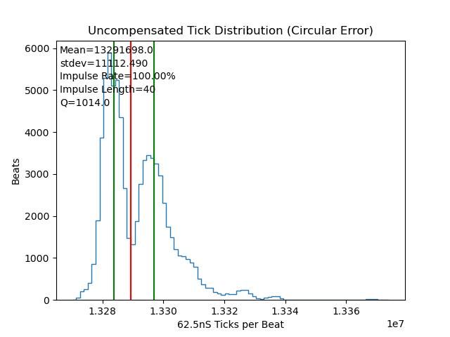
Tick distribution shows low Q and a wide double spike. This is characteristic of over-impulsing:
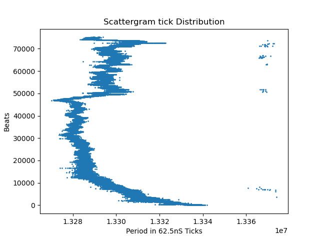
Same problem with the tick scattergram, showing period is seriously unstable over time. The standard deviation is about 5mS, about 500 times too high:
The obvious next step is to reduce Impulse power, but I'm thinking it's time to rebuild the clock to profit from lessons learned. I'll type up the improvement list later for comment.
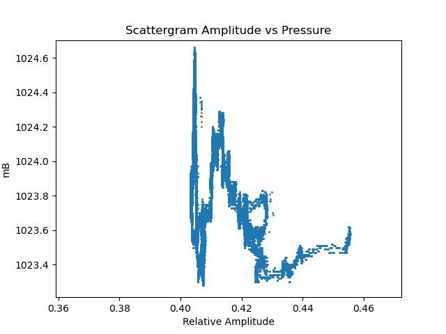
Duncan asked about Amplitude vs Pressure, and whilst they correlate, it's not as I expected:
Like Amplitude vs Temperature the relationship wanders. Although at a given time seems Amplitude & Pressure map consistently to a given X,Y coordinate, at other times they map somewhere else! Can anyone explain it? My best guess is another independent variable is skewing the relationship.
I'm a little disheartened. Attempting to improve the clock has made it worse. AGAIN!
Logging the duration of the interruption gets you a measure of the increase or decrease in amplitude.
regards Martin
True, but then you might as well just measure velocity (via duration) at bottom dead center as John is doing.
Finding BDC is a matter of equalizing left and right swings, which could be done to a microsecond or so (i.e., a part in 10^6) with a decent setup. That is easier than measuring an offset from BDC.
Finding the duration (for velocity) is likely a source of more significant errors, since it depends on measuring the flag or gap, and knowing the aperture of the sensor, perhaps even taking into account diffraction, etc. None of that is likely to be achieved to the same part in 10^6.
I don't think it matters what the actual value of amplitude is, what matters is that it is constant, or that you can compensate for change. In either case the width of the flag is fixed, so if you measure obstructed time and cycle time you've got all you need. I suppose the flag should be made from a low expansion material.
Logging the duration of the interruption gets you a measure of the increase or decrease in amplitude.
regards Martin
True, but then you might as well just measure velocity (via duration) at bottom dead center as John is doing.
Which neatly illustrates the point that it’s the motion that is required to be constant and if it is the maximum velocity, the amplitude and the time between two points will all be constant too. I agree with Duncan, pick what’s easiest to measure for you it doesn’t really matter.
I don't think it matters what the actual value of amplitude is, what matters is that it is constant, or that you can compensate for change. In either case the width of the flag is fixed, so if you measure obstructed time and cycle time you've got all you need. I suppose the flag should be made from a low expansion material.
That's my position. I don't care what the absolute amplitude is, I only need a number that indicates if it's going up or down. I don't care where BDC is or what the exact sensor offset is from it. Ideally it should be adjustable for practical reasons, and tuned for best results.
Measuring actual amplitude is an interesting challenge though. Don't see why I couldn't calibrate my crude version of John's formula by graphing microscope observed amplitudes against their equivalent electronic numbers. Once the relationship between actual and magic number is known, actual amplitude is just a matter of setting the scale.
Bit like calibrating an NE555 oscillator capacitance meter by plugging in a series of known value capacitors and marking up the analogue scale.
Do you want to sit squinting through an eyepiece 24 hours a day noting down values of amplitude every 2 seconds? Even then HJ only measures at the end of travel, he is not measuring magnitude, he is noting difference. I suppose he could have mounted his microscope on a long micrometer affair, but even then he'd struggle for 10ths of inches. The half amplitude of a 1m pendulum is ~52mm if it is swinging +- 4 degrees, so measuring to 1/00 mm as in the link is one part in 5200. The electronic flag method can get times to one part in 16 million. I'm pleased to see that even back in the 40s, sensible people were talking in metric.
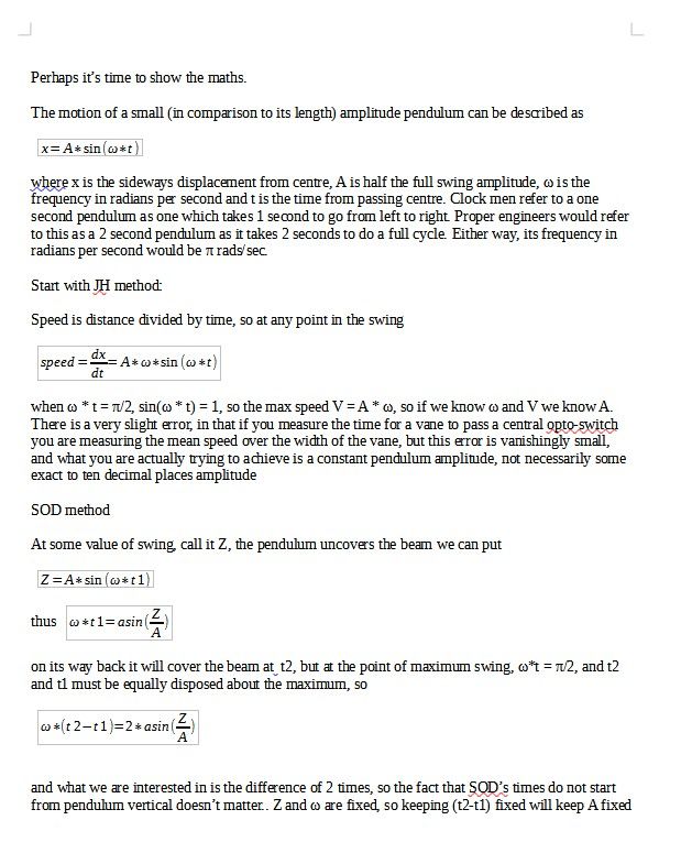
For those sad enough to want to see my sums see below
Well, Duncan … I have read it, and at least we are in agreement on “what you are actually trying to achieve”
i.e.a constant pendulum amplitude, not necessarily some exact to ten decimal places amplitude
That sums it up nicely ^^^
But what I still fail to understand is why, therefore, everyone wants to derive something which can be physically measured.
On the reasonable assumption that any system producing amplitudes substantially greater or less than our target can be disqualified [because it renders the pendulum not fit for purpose] all we need is to detect ‘delta’ variations from the target value, and I suspect that even a 640 pixel wide sensor would easily suffice for that. … Ideally, every swing would shade the same pixel and, as I suggested before, scaling such that 635 pixels saw 1/4” we could have a central target line with +/- 317 pixels for detection of over-swing/under-swing [other scaling values are readily available]
I have no axe to grind … I just don’t understand why it is considered better/easier to do these calculations.
You have to have some kind of sensor to measure the period. You can use the same sensor to keep check on the amplitude, ie is it increasing or decreasing. You don't need to do any sums, if the measured velocity goes up reduce the impulse, or miss one out. Why introduce extra complication.
That’s why I have already suggested the use of a camera sensor.
MichaelG.
I should really stay out of this discussion, but: To directly measure the amplitude, a video camera would be needed, not a still camera. Moreover, it would need to have very fast frame rates and other features of merit for fast operation. A typical video camera operating at 60 fps would likely provide quite low position resolution. There are probably ways to get around that, e.g. by processing a sequence of frames to estimate the actual end point, but it's not going to be easy.
Another point: One must be careful about the difference between "precision" and "accuracy."
I think there are two reasons for wanting to "measure" amplitude.
The first is diagnostic – since period reduces with increasing amplitude (other things being equal), then being able to measure amplitude variations can help to identify and fix problems.
The second is the reverse of that medal – since amplitude affects period, controlling it to make it as constant as possible takes away a source of error.
The first can conveniently be done through a velocity measurement provided that the period is known as well, or could in principle be done with a camera as Michael suggests.
The second can be done very well with a "one pixel" camera, an opto that just gets triggered by any overtravel and inhibits impulsing. Doug Bateman's clock (described in HJ in 1972) did this and he set it up so that the impulse spends most of its time going hit/miss on alternate swings. Since the loss in amplitude between swings is the the decrement, related to the Q, and Q was measured, it could be inferred that the amplitude was being sensed to within 0.5 seconds of arc by the opto sensor. My pendulum uses a similar principle and though I haven't yet quantified it, just looking at the impulsing pattern on a scope looks like it's spending most of its time alternating hit and miss, so given my Q is not dissimilar I may be getting a similar accuracy.
That’s why I have already suggested the use of a camera sensor.
MichaelG.
I should really stay out of this discussion, but: To directly measure the amplitude, a video camera would be needed, not a still camera. Moreover, it would need to have very fast frame rates and other features of merit for fast operation. A typical video camera operating at 60 fps would likely provide quite low position resolution. There are probably ways to get around that, e.g. by processing a sequence of frames to estimate the actual end point, but it's not going to be easy.
Another point: One must be careful about the difference between "precision" and "accuracy."
.
I was suggesting the use of a webcam 640×480 pixels and useable on a Raspberry Pi
Specific reference to the sensor was because that provides the ‘measuring stick’
The frame-rate is of no great consequence, because the Region of Interest is where the swing is about to change direction. [ think about it ]
and finally … ‘one’ is conversant with the the difference between "precision" and "accuracy."
Moderator Note: Concerned to see a grumpy note has crept into the thread. Please try to keep it polite!
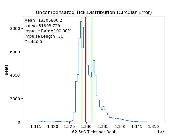
Today's graphs show yesterday's Impulse reduction wasn't enough. Though sharper (Q=440), the distribution is still skewed and has 3 peaks. (Ideally only one, same slope on both sides, with a narrow base, Q=10000-ish) Not like this:
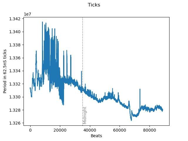
The log shows changing impulse caused an outbreak of wild swings that nook nearly 3 hours to settle:
Not sure why, except I happened to change impulse just as the central heating came on, so two changes at once, three if relative humidity counts. (Don't believe it does.)
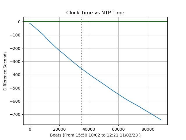
Otherwise good news: clock vs NTP (drift) is pretty constant, with no time jumps due to the beam not being broken cleanly.
An observation: despite being out of adjustment and behaving badly, my clock still keeps mildly good time on average. I've noticed this effect before and believe other pendulum clocks probably behave the same way. However, it may not matter! If a mechanical escapement causes impulse strength to vary and the effect averages out, it's not easy to see the error. Individual second beats can be obviously wrong, making the clock an untrustworthy sub-second timekeeper, but there's a good chance the 'going' mechanism will average them out so the clock performs well over days, weeks and months. Especially well if it has no seconds hand!
Moving on I've reduced impulse again and have to wait several hours to see what happens next. It's like watching paint dry!
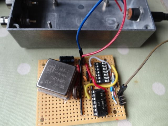
Diverted this morning into rebuilding my OCXO, after wiring the divider IC mirror image in the the first version. The new one doesn't work! Note that the divider chip isn't plugged in, and can't be to blame.
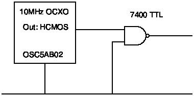
The part of the circuit that's not working is the easy bit! I buffer the OCXO output into a NAND gate, to increase the fan out:
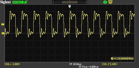
Input to the NAND gate from the OCXO:
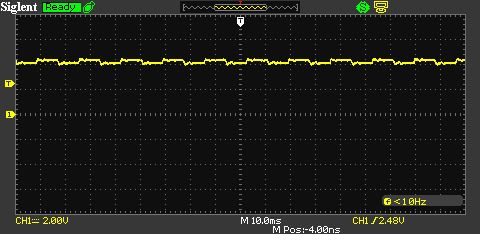
And then it all goes wrong, output from the NAND gate:
My electronics, never brilliant, is also rusty. I believe HCMOS should be able to drive a single TTL gate, and also that I can leave the inputs and outputs of the other 3 gates on the 7400 floating.
The mark one version worked OK, the only difference being I wired the other gate input HIGH, rather than LOW in this one, simply because the ground rail is adjacent. Surely this wouldn't stop the gate working?
Have to go out this afternoon so I'm hoping a clever member can tell me what I'm doing wrong.
The mark one version worked OK, the only difference being I wired the other gate input HIGH, rather than LOW in this one, simply because the ground rail is adjacent. Surely this wouldn't stop the gate working?
Yep, it will….
An AND needs both in's to be high for the out to be high, else the out stays low forever…NAND just inverts the state is all…So high on one, then the O/P toggles in sync with the 2nd in.
Aargh, of course it will. Now I feel REALLY stoopid! I might never have twigged due to becoming engrossed in unlikely explanations. If only I'd drawn a truth table…
and you should really pull at least one input of the other gates low. Noise on undefined inputs causes the outputs to switch putting noise on the power rails.