Posted by Michael Gilligan on 08/02/2023 06:11:33:
Posted by S K on 08/02/2023 04:23:37:
Posted by John Haine on 07/02/2023 22:09:35:
Actually it's only convention to think in terms of amplitude. We could just as well write all the equations in terms of velocity, then measuring the velocity is quite natural.
Interesting point – I can see that, thanks.
[…]
.
I confess to being particularly thick-headed at this ungodly hour, but I’m afraid the point is lost upon me:
If the equations are written in terms of velocity, then the peak of the swing is at velocity=Zero
So far, so good … but, if we are all agreed that a real pendulum is not isochronous, surely we need to know at what point in space that occurs
I must be missing something … What mathematical conjuring makes it possible to ‘tune’ the pendulum without controlling its arc ?
MichaelG.
Edited By Michael Gilligan on 08/02/2023 06:12:47
I would guess that:-
As you will be aware pendulums oscillate by exchanging kinetic energy with gravitational potential energy. Maximum velocity is proportional to KE and max amplitude proportional to PE. You can either use amplitude or velocity as your control element. There is no need to convert the one into the other. If one is stabe the other will be too. The fly in the ointment is how accurately can you measure changes in either. Personally I would say at a quick glance that amplitude is easier to measure to greater sensitivity than velocity.
There is no need to convert the one into the other. If one is stabe the other will be too. The fly in the ointment is how accurately can you measure changes in either. Personally I would say at a quick glance that amplitude is easier to measure to greater sensitivity than velocity.
Be interesting to see if John Haines agrees with what follows:
John states Amplitude = W x P/(2*pi*T)
What I call 'Relative Amplitude' is P / 2T, which is a simplified form of John's formula; my 'Relative Amplitude' is proportional to John's Amplitude.
Neither of us cares what the actual amplitude is. We both use an offset beam sensor to generate a number that varies with amplitude, and use it to trigger Impulses. I set the trigger threshold manually, adjusting by eye for a short swing that breaks the beam cleanly and then providing just enough impulse energy to keep the clock running reliably.
We both use Precision Event Timers, allowing individual pendulum swings to be measured with high resolution. Off the cuff I can't think of a way of measuring amplitude with a simple electronic or mechanical method; it needs a PET to work. John uses a picPET, from Tom van Baak. Tom's method can be implemented on other Microcontrollers, and my version works on Arduino AVR boards. The main advantage is more functions can be added to an Arduino PET, such as reading temperature, pressure, and humidity ensors, but I run an entire clock with sensors, GPS, and a built-in PET function on an Arduino Mega2560. However, the point is that a high-resolution PET allows John and I to get a usable approximation of amplitude by measuring small changes in bob velocity.
The Chronova article Michael identified recently has more on amplitude. It's in the December 2022 Horological Journal.
Be interesting to see if John Haines agrees with what follows:
…..
Dave
Edited By SillyOldDuffer on 08/02/2023 10:00:01
Broadly, except to say that my sensor is not (deliberately) offset, though it's very hard to get it exactly centred. I now average the measurements for LR and RL swings to compensate.
I don't agree with Martin, my amplitude "measurement" is resolving to better than 0.01mm without much trouble, and for each cycle. That might be possible with an image processing system analysing the images from a microscope, but that would be a lot more complicated to set up.
Posted by Michael Gilligan on 08/02/2023 06:11:33:
Posted by S K on 08/02/2023 04:23:37:
Posted by John Haine on 07/02/2023 22:09:35:
…..
I must be missing something … What mathematical conjuring makes it possible to ‘tune’ the pendulum without controlling its arc ?
MichaelG.
Edited By Michael Gilligan on 08/02/2023 06:12:47
Well I'm actually measuring it's velocity, so I could in principle simply control the impulse to maintain the peak velocity constant.
.
Therein, I think, lies the essence of my concern/confusion/whatever … Peak velocity occurs when the pendulum is vertical, but the ‘tuning’ seems more directly related to the magnitude of the swing.
Be interesting to see if John Haines agrees with what follows:
…..
Dave
Edited By SillyOldDuffer on 08/02/2023 10:00:01
Broadly, except to say that my sensor is not (deliberately) offset, though it's very hard to get it exactly centred. I now average the measurements for LR and RL swings to compensate.
I don't agree with Martin, my amplitude "measurement" is resolving to better than 0.01mm without much trouble, and for each cycle. That might be possible with an image processing system analysing the images from a microscope, but that would be a lot more complicated to set up.
I thought I said that I felt that amplitude was easier to measure is n't that what you suggest? My comment was just an impression, you lot are actually doing the measurements so would have a better feel for it.
A pendulum with a particular period and amplitude has a particular maximum velocity, so if you measure this maximum velocity, you can impulse the pendulum as necessary. The maths is not difficult, but putting equations in this forum is laborious.
On measuring amplitude, I think that astronomical types measured pendulum amplitude with a microscope and adjusted timings with some kind of tables.
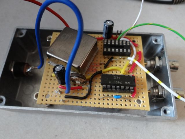
Someone has wired the empty socket back to front. He remains nameless to spare his embarrassment. The mistake is so serious I can't bear to think about it. Probably have to make another board from scratch. Started badly and finished worse. Works perfectly apart from the divider chip, where all the pins are wrong.
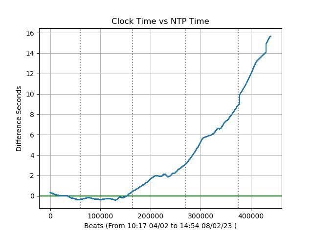
Meanwhile the clock is drifting even more badly:
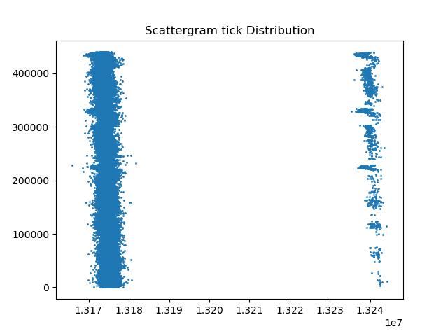
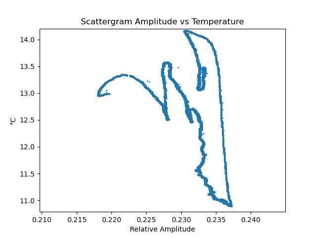
I think the problem is over impulsing, probably because the suspension is coming loose! The scattergram below shows two modes of oscillation, the dominant one centred near at 13175000 ticks per beat, the weaker near 13240000 ticks per beat. In the past the effect has been caused by over impulsing:
The weaker mode is getting stronger with time. As the impulse is accurately constant and nothing else has changed. I think the drift is due to a mechanical problem in the suspension.
Posted by Michael Gilligan on 08/02/2023 20:38:10:
Posted by duncan webster on 08/02/2023 14:18:56:
[…]
On measuring amplitude, I think that astronomical types measured pendulum amplitude with a microscope and adjusted timings with some kind of tables.
.
Yes … and that’s consistent with my comment to John about mind-sets:
The velocities that Astronomers tend to think of are very large
The measurement of small angles is commonplace … ergo, they excel at it.
MichaelG.
I very much doubt they had the facilities to accurately measure the peak velocity to parts per billion, so there was no other way than measuring amplitude.
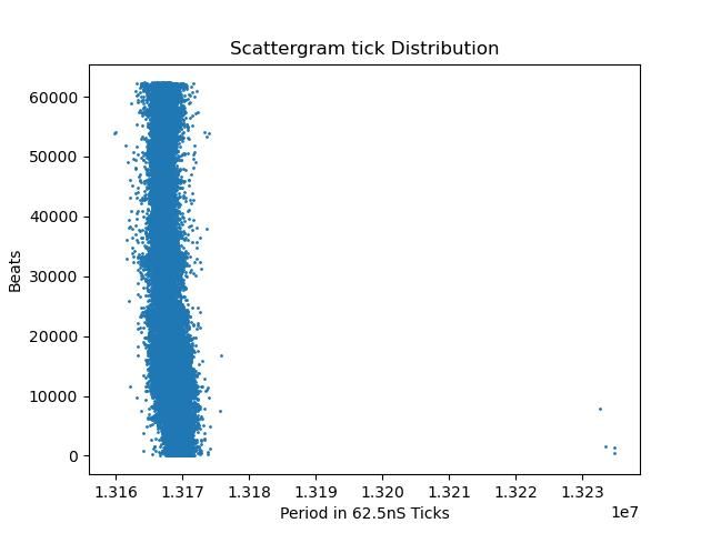
This morning's results are revealing. Last night I restarted the clock after finding it was being over impulsed, reducing impulse from 28 to 24.
The second mode of oscillation has almost disappeared, with 4 examples far right bottom when the clock starts.
Some off-centre vibration is expected because the clock auto-starts by applying a 2 second pulse to the electromagnet. The pulse is powerful enough to pull and hold the bob on the pole. When the start pulse ends, the bob swings violently for about 10 minutes, stays somewhat disturbed for about an hour, after which it swings up to the design amplitude, which is small. Or rather that's what I mean the bob to do! (In a an earlier version I attempted to start the clock gently by pulsing the electromagnet weakly at the pendulum's resonant frequency. Worked unreliably when I had to physically move the clock to make software changes. Ought to have another go now the clock doesn't have to be touched, otherwise I have to ignore the first 5000 statistics after a restart.)
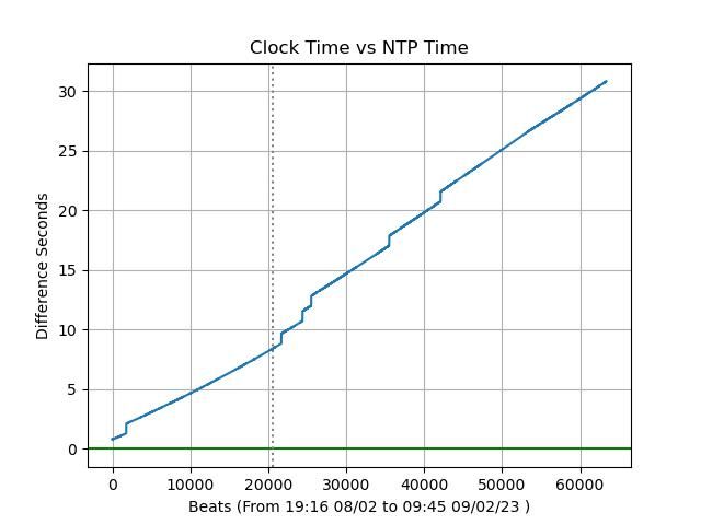
Looking at the drift graph shows another problem – steps are back:
The vertical dotted grey line marks midnight.
Steps are caused by the bob not quite breaking the beam reliably. They're caused by the impulse being slightly too weak to pull the bob fully across the beam 100% of the time. Bit of a quandary: increasing impulse causes the amplitude to rise excessively, whilst reduced impulses cause unreliable beam breaking!
What to do about it? Ideas so far:
Sharpen the beam so the bob breaks it earlier.
Provide a method of moving the beam sensor so the bob breaks it earlier.
Go back to governing amplitude, so the bob isn't impulsed above a certain threshold. The code for this already exists, turned off after I discovered my pendulum keeps better time when impulsed lightly on every beat, rather than more powerfully after 'n' beats. I probably need to be more sophisticated, by always impulsing below a minimum threshold, and never impulsing over a certain maximum.
Tilt the clock slightly so the bob hangs a little closer to the sensor at BDC.
Other suggestions welcome!
Looking at the earlier strange Amplitude vs Temperature graphs showed the Possum look is due to a succession of rounding errors causing the graph software to struggle with a narrow range of quantised data. However, something odd is going on:
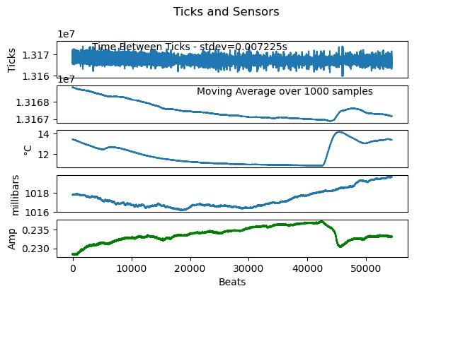
The graph above, scaled to hide rounding striping, shows there a weird relationship between temperature and amplitude. The two correlate in a non-linear way. Although amplitude obviously follows temperature, the path is inconsistent. For example, six amplitudes correlate with 13°C.
The effect of temperature on amplitude can also be seen on the next graph, green line:
What fun!
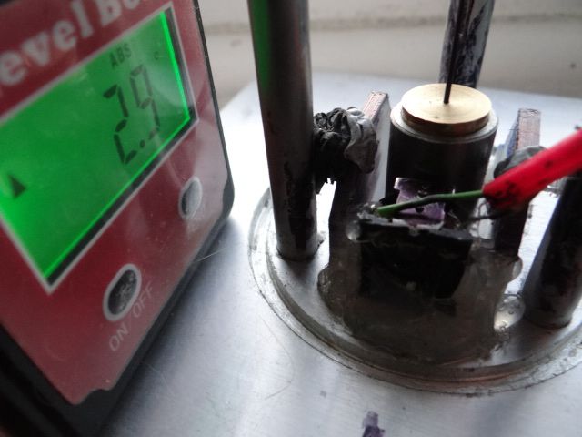
As it's easiest to do, I'm going to tilt the clock slightly.
I remember mentioning, a while back, that Jim Arnfield had considerable success by putting sender and receiver each at the bottom of a blackened tube of suitably small diameter. … I would think it worth a try.
Posted by Michael Gilligan on 09/02/2023 17:59:46:
Dave,
I remember mentioning, a while back, that Jim Arnfield had considerable success by putting sender and receiver each at the bottom of a blackened tube of suitably small diameter. … I would think it worth a try.
MichaelG.
Yes, it's a good idea, already noted, and I made a couple of brass tubes this afternoon intending to do just that. Unfortunately I forgot how little room there is inside the clock – only a few mm each side of the bob, barely enough space for a washer. That's why I used Bluetack, and probably put too much on. Serves me right, it was a bodge.
Taking the cover on and off to fix the problem is a pain, but I'm off to do it now. My language is bluer than the Bluetack!
Posted by Michael Gilligan on 09/02/2023 07:07:08:
This ‘debate’ has become hopelessly unproductive
… I apologise for asking my question.
MichaelG.
Michael, please don’t apologise, questions make people think so they can be answered. Your question has prompted me to look in detail at the maths. Both JH method and SOD method only measure amplitude accurately IF the frequency is known. They are not as good at measuring amplitude as actually measuring it direct if the pendulum frequency is changing and you're not keeping track. I think SOD is, not sure about JH, but I wouldn't be surprised. One could argue that it won't change, but it will, due to temperature and buoyancy
My method is to measure the amplitude directly with a second slotted opto. It has a Schmidt trigger so that it is a go/noGo output. This isn't why I did it that way, my processor has a ropey oscillator clock, so I didn't want to rely on it to work out amplitude, I want the pendulum to do it's own thing.
… I became aware that I was distracting from Dave’s amazing project by questioning the underlying methodology that both he and John are happily using, and thought it right to apologise for that.
Being more comfortable with optical measurement than I am with mathematical analysis, I would instinctively choose to measure amplitude directly … but I don’t want to argue the pros and cons.
Unfortunately, I am not currently in a position to do any practical experimentation … so I’m just along for the very interesting ride, and trying to keep the grey cells active.
Aha, now I think I see the issue! To characterise the clock I measure the times of the leading and trailing edges of the pulses from the opto sensor which detects a slot in a vane as the pendulum passes bottom dead centre. Actually 4 edge times are acquired from 2 swings and the average of these gives the time of the cycle peak. Differencing the peak times of successive cycles gives period. That period value is used in the next cycle's data acquisition to compute an amplitude value from each pulse of that next cycle. So there is an assumption that the period will be pretty well correlated from one cycle to the next, but essentially the amplitude calculation is based on the measured period from moment to moment.
All this happens in the R-Pi which is logging the timing data coming off the picPET. There is no connection from that to the clock electronics apart from a feed of the opto pulse. The pendulum amplitude is separately sensed by another opto, offset from the BDC one, which if it sees the edge of the slot in the vane inhibits the impulse drive for the next 2 swings. According to the "time-based" measurement this seems to be regulating the short-term variation of amplitude to +/- 5uM or so but that could include some error in the period measurement itself.. There is a long-term amplitude variation too which is clearly caused by temperature that I don't understand yet, amounting to about 0.02mm (at least for the limited range of cold temperatures this week).
so now, as the saying goes, we're all singing from the same hymn sheet
Not if I can help it – the devil has all the best tunes!
Back to amplitude – I don't believe any of my books explain how it was measured in the past. Must have been done because the old masters knew period varies with amplitude.
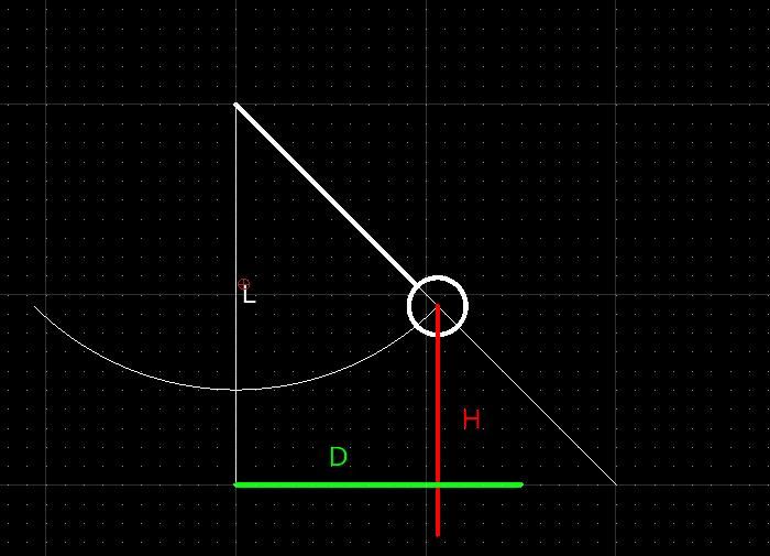
My guess is they did it by setting a degree scale behind a pointer on the bob to see the apex. Not too difficult because the bob stops and reverses at the apex. A microscope would give an accurate result. And if it wasn't good enough, screw adjusting the microscope up/down and sideways to put cross-hairs on the apex would give the accurate linear measurements needed to calculate amplitude from D and H below. Michael put the idea in my head!
Mechanically measuring amplitude only gives the average. An electronic Precision Event Timer, such as John's picPET or my ardPET, measures time with enough resolution to 'see' tiny variations in period and amplitude within individual swings. No idea if amplitude changes are important, or root cause, but my results show a strange relationship between temperature and amplitude. Most likely explained by a third variable in play, but it's a mystery to me!
I have to be brave now and look at what my clock did last night. Expecting it to be wildly out of adjustment because it's been moved, re-levelled, blobbed on the sensor, impulse increased to keep it running reliably, and I changed the software slightly. Not good to change more than one thing at a time, but needs must when the devil drives and I'm short of time…