Experimental Pendulum Clock

Advert

Experimental Pendulum Clock

Home Forums Clocks and Scientific Instruments Experimental Pendulum Clock

Viewing 25 posts - 351 through 375 (of 562 total)
  • Author
    Posts
  • #631374
    John Haine
    Participant
      @johnhaine32865

      I believe that it was actually Hope-Jones who implemented a chain synchroniser quite early last century. At any rate I have seen one at The Clockworks. Incidentally that's a museum that is well worth at least one visit.

      Advert
      #631383
      S K
      Participant
        @sk20060

        That chain timing controller is interesting. But I have to imagine it causes additional friction, as well as other disturbance due to the free hanging region of the chain applying slight side-ways resistance on the shaft as it rocks. Also, I think it inevitably has to lengthen and shorten slightly as the tray rocks back and forth too, meaning the amount of weight on the tray changes slightly too. In the case of this clock, these effects are evidently lower than the temperature and barometric pressure effects, though.

        I've imagined a battery-operated servo of some sort mounted to the shaft, or perhaps better-yet hidden inside a bob's case, to adjust the weight without such effects.

        #631478
        SillyOldDuffer
        Moderator
          @sillyoldduffer

          Good to report something worked for a change, well nearly,

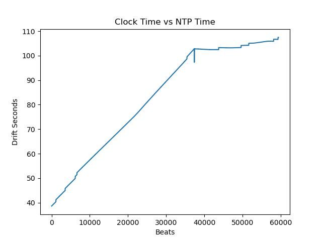
          This graph shows my clock gaining more or less constantly relative to Network Protocol Time until I applied drift correction at beat 37360, after which the line becomes more horizontal.

          3101comp.jpeg

          The result is marred by 5 step jumps, all of which, I suspect are due to the bob not quite breaking the beam. The faulty timings occur in pairs that sum close to a correct period, but on the slow side:

          Beat Time

          6186 4205678
          6187 8967229 = 13172907

          6627 4202164
          6628 8968950 = 13171114

          43724 4233017
          43725 8937554 = 13170571

          In hope of curing incomplete swings I've increased Impulse by one notch and left the clock running. A better way would be to move the beam, or to pass it through a slit, but that means taking the cover off. I'll do it when the long awaited new suspension is finished.

          Dave

          Edited By SillyOldDuffer on 31/01/2023 17:20:13

          #631507
          duncan webster 1
          Participant
            @duncanwebster1
            Posted by duncan webster on 07/01/2023 17:20:59:

            Multivariant analysis is far too clever for me, but you could perhaps reduce the number of variables. Temperature, pressure and humidity all change the air density, which affects buoyancy, so you can calculate density, then you only have that and the temperature effect on length to worry about instead of 3

            Edited By duncan webster on 07/01/2023 17:21:34

            So I've had a go at this, and it's not as easy as I thought. It would be easier to produce a set of table of density vs pressure, temperature and relative humidity, a sort of 3D matrix. Can the clever controller cope with this?


            Ignore this, I think I've worked out how to do it

            Edited By duncan webster on 31/01/2023 20:24:47

            #631512
            SillyOldDuffer
            Moderator
              @sillyoldduffer
              Posted by duncan webster on 31/01/2023 20:04:39:

              Posted by duncan webster on 07/01/2023 17:20:59:

              Multivariant analysis is far too clever for me, but you could perhaps reduce the number of variables. Temperature, pressure and humidity all change the air density, which affects buoyancy, so you can calculate density, then you only have that and the temperature effect on length to worry about instead of 3

              Edited By duncan webster on 07/01/2023 17:21:34

              So I've had a go at this, and it's not as easy as I thought. It would be easier to produce a set of table of density vs pressure, temperature and relative humidity, a sort of 3D matrix. Can the clever controller cope with this?

              Ignore this, I think I've worked out how to do it

              Hurrah! I was worrying about how the size of the matrix. floats are 4 bytes each, so a 10x10x10 array would take 4kb of memory, so they can take up a lot of room. No problem on a PC but microcontrollers don't have much RAM.

              Dave

              #631769
              SillyOldDuffer
              Moderator
                @sillyoldduffer

                Still ploughing on, three steps forward, two back.

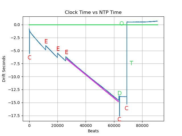
                After various software tweaks I set the clock to compensate for pressure and temperature but not drift and let it run overnight until lunchtime. Purpose, to identify the drift rate from scratch and apply it. Result, a mix of good and bad news:

                0202drift.jpg

                The green line represents perfection, the settings at which my clock and NTP agree exactly.

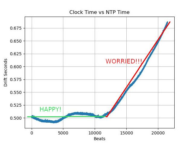
                Good first. The purple line establishes the drift rate, and the necessary compensation was applied at point D, resulting in a flat line. After waiting to confirm it, I resynchronised the clock to NTP, causing the line to jump to point O, and carry on flat, about 0.18s faster than NTP. The line stays reasonably flat for about 10000 beats, just over 2 hours,

                Bad news!

                • Commands sent to the clock disturb timekeeping at the points marked C. It appears the clock is correct and the error occurs in the raspberryPi when the log is timestamped. Probably a software fault.
                • The beam break sensor misreads period 3 times at points E. Hardware fault.
                • Setting the clock to NTP time causes a synchronisation error. Design fault! The clock is set to the nearest second, but the raspberryPi should wait until the exact next second before sending the synchronisation message. Otherwise the clock starts wrong by up to 1 second, not good when it's aiming for sub-millisecond accuracy.
                • Although it should be compensated out, Temperature effects are still visible. Maths, logic or programming error.
                • Worst of all, corrected drift doesn't stay parallel with the green line. OK for a couple of hours, then it suddenly rises – red line below:

                0202worry.jpg

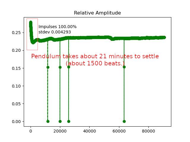
                Lastly, the relative amplitude graph shows my pendulum takes a long time to settle after a cold-start, red box below:

                0202ampsettle.jpeg

                Arguably, the graph suggests turbulence lasts for about an hour. I think the clock should be allowed to run for at least an hour before trusting measurements.

                Dave

                #632027
                SillyOldDuffer
                Moderator
                  @sillyoldduffer

                  Too early to break out the champagne, but today's results are best yet. I'm encouraged!

                  Yesterday I improved the clock software so that it would synchronise closer to the NPT time command. The program on the main computer was changed so that, on receipt on a synchronous command from me, it waits until the next whole second before telling the clock. This eliminates most of the error due to ignoring microseconds at the sender.

                  In the clock, when a synchronisation time message arrives, I obtain the bob position by reading the pendulum timer/counter. This varies between zero and about 13175309 ticks. As each tick is 62.5nS, how far through a swing the bob is can be calculated accurately. This value is used to adjust the gearTrain so that counter time aligns with pendulum ticks. How good it is varies, but better than 0.1s is typical. More work needed.

                  I also changed the clock so that it only sends messages immediately after time reports. As these are written immediately after a 'tock', any extra messages have a whole pendulum period in which to send. Previously, clock messages where sent immediately, which meant the microcontroller could be tied up when a 'tock' was received, and delay reporting it. Touch wood, seems to have stopped glitches. The graph is clean, and no bad ticks are in the log:

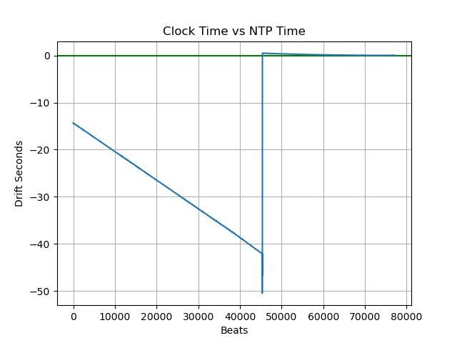
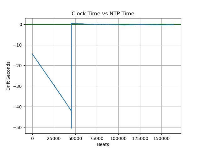
                  0402happy.jpg

                  The graph shows the clock running uncompensated for 45000 beats to establish drift rate, then the spike when drift compensation was loaded and the clock resynchronised to NPT. Thereafter the clock stays close to the green line, showing it's not far off NPT. Actual numbers:

                  ClockEnd = 2023-02-04 16:32:00.388850
                  NPTEnd = 2023-02-04 16:32:00.376452
                  Difference = 0.012s 0.000019% (0.195ppm)

                  The pendulum is unusually well behaved so far in this run, reporting Q=13883, Hopefully because the impulse is right and needn't be touched again.

                  It's what happens next that matters. With luck all is now good and the clock will stay close to NPT for months. More likely next time I check, it will have veered off for no apparent reason. I know the temperature and pressure compensation isn't spot on, but earlier runs showed deviations with no obvious cause. I suspect the suspension because it's not well made.

                  Dave

                  #632032
                  John Haine
                  Participant
                    @johnhaine32865

                    Very promising Dave! I've reached the point of re-writing my Python logging code for the new clock, having lashed up a pP07 and one of those OCXOs on a bit of veroboard. What environmental sensor are you using? With luck I can start logging tomorrow….

                    #632037
                    SillyOldDuffer
                    Moderator
                      @sillyoldduffer
                      Posted by John Haine on 04/02/2023 18:25:59:

                      Very promising Dave! I've reached the point of re-writing my Python logging code for the new clock, having lashed up a pP07 and one of those OCXOs on a bit of veroboard. What environmental sensor are you using? With luck I can start logging tomorrow….

                      It's a BME280, not too expensive but quite quick with good resolution,

                      My OCXO is nearly ready too. It's on Veroboard with two IC holders, and an Eddystone box is finished with two BNC sockets and a power socket. Would have had it working except I cut the board so the tracks are the wrong way round! Now I have to rethink the connections and find a 10k pot.

                      Do you have any ideas about setting the OCXO to exactly 10MHz? I'm wondering about comparing BBC R4 Longwave (198kHz) to the OXCO with an oscilloscope. Or using an SDR (which I have) to zero the OXCO with WWV on 10MHz. Trouble is WWV comes from Colorado, and the signal is patchy. Pity the OXCO isn't working, because WWV is usable at the moment. RWM (Moscow's time signal) is usually loud on 9.996MHz but I'm boycotting all things Russian at the moment!

                      Dave

                      Edited By SillyOldDuffer on 04/02/2023 19:09:25

                      #632049
                      Michael Gilligan
                      Participant
                        @michaelgilligan61133

                        Nice work, Dave … your perseverance is being handsomely rewarded.

                        MichaelG.

                        #632059
                        John Haine
                        Participant
                          @johnhaine32865

                          Dave, I've put a pot on the frequency control input and just left it half way up for the moment. It would be nice to set it more precisely but it's likely to be near enough for all practical purposes. Now having a picPET on the board, if I had a GPS 1pps signal I could just feed that in and adjust the pot to get precisely a 1 second period as measured at the data output…

                          I'm using a BME280 also, I had some problems with the recommended Python library but found you actually need to use an old version to make it work!

                          #632060
                          duncan webster 1
                          Participant
                            @duncanwebster1

                            Anthhorn is broadcast at 60 kHz with an accuracy of 2 parts in 10^12.

                            #632090
                            John Haine
                            Participant
                              @johnhaine32865

                              It does, but receiving it and synching a micro to it doesn't seem to be so easy. Do you know of any low cost receivers Duncan please? I have tried receiving dcf77 using a module recovered from a cheap weather station but without success.

                              #632094
                              SillyOldDuffer
                              Moderator
                                @sillyoldduffer
                                Posted by John Haine on 05/02/2023 08:45:16:

                                It does, but receiving it and synching a micro to it doesn't seem to be so easy. Do you know of any low cost receivers Duncan please? I have tried receiving dcf77 using a module recovered from a cheap weather station but without success.

                                Same problem here. The 60kHz signal is weak. DCF77 (Germany) is stronger. I suggested 198kHz (BBC Radio 4) because the transmitter is powerful, and frequency locked to a Rubidium clock. Although R4 doesn't issue time synchronisation signals like WWV, MSF, DCF77 and others, that doesn't matter in this application because all we need to do is set a 10MHz oscillator as accurately as possible. The OCXO John and I are using claims 200 parts per billion, so we ought to set it within ±1Hz of 10MHz. (Is that right: 10000000 * 200/1000000000 = 2)

                                As I have a GPS Module that outputs accurate 1 second pulses, I think I'll use picPET technique. That is clock the PET with the OCXO and measure how long the PET thinks GPS seconds are, then adjusting the OCXO to 10,000,000 pulses per GPS second.

                                Actually I'll use my ardPET because I can modify the code. My OCXO unit contains a divide by 2 and divide by 5 IC, so it can output 1, 5 and 10MHz. I'll feed 1MHz into the PET modified to count pulses for, say, 100 GPS seconds and then tweak the OCXO for 1,000,000,000 pulses in 100s. Summing over 100 seconds should improve setting accuracy by providing more resolution and by averaging out some of the error.

                                Another thought was to use a couple of pic dividers to take the OCXO and Radio 4 down to audio frequency, and then compare with Lissajous. But I think the PET approach is easier, and I already have GPS.

                                Having struggled to exploit radio Frequency Standards, I think GPS is the better option provided there's a clear view of the sky. A GPSDO would be nice…

                                Dave

                                #632095
                                Michael Gilligan
                                Participant
                                  @michaelgilligan61133

                                  I’m not sure how to pick the useful bits out of this, but:

                                  I noticed last night that NPL seems to ‘speak with forked-tongue’ about the availability of this carrier signal

                                  **LINK** : https://www.npl.co.uk/msf-signal

                                  [quote] The MSF radio signal is a dedicated standard-frequency and time broadcast that provides an accurate and reliable source of UK civil time. It is available 24 hours a day across the whole of the UK and beyond. The signal operates on a frequency of 60 kHz and carries a time and date code that can be received and decoded by a wide range of readily-available radio-controlled clocks.

                                  The MSF signal is transmitted from Anthorn Radio Station in Cumbria by Babcock International, under contract to NPL. The signal covers the whole of the UK, and can also be received throughout most of northern and western Europe. It is monitored against the national time scale UTC(NPL) and corrected when necessary, ensuring that the transmitted time is always correct. [/quote]

                                  At first sight ‘It is available 24 hours a day across the whole of the UK and beyond’ appears to be an unambiguous statement … but dig a little deeper, and there are a lot of caveats.

                                  To apply useful synchronisation, it would appear to be necessary to do this on an ad hoc basis, as-and-when the carrier is actually [and unpredictably] available.

                                  Eagerly awaiting someone’s clever work-around.

                                  MichaelG.

                                  #632097
                                  duncan webster 1
                                  Participant
                                    @duncanwebster1
                                    Posted by John Haine on 05/02/2023 08:45:16:

                                    It does, but receiving it and synching a micro to it doesn't seem to be so easy. Do you know of any low cost receivers Duncan please? I have tried receiving dcf77 using a module recovered from a cheap weather station but without success.

                                    I bought one off ebay for very little. I used it to pulse a slave clock as it had a square wave 1 second on one second off output. I took it out eventually as when anthhorn was down for maintainable the clock went doolally. I'll have a search later on, if I can find it you can have it. With a software event timer you could count ticks per 2 seconds from the OCXO.

                                    #632111
                                    SillyOldDuffer
                                    Moderator
                                      @sillyoldduffer

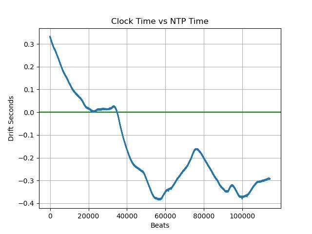
                                      Today's report, clock still close to Network Protocol Time, staying close to the green zero line:

                                      0504driftscale.jpg

                                      Sadly zooming in by changing the scale shows a swing of ±0.3s either side of NPT:

                                      0502drift.jpg

                                      Going to collect more data before investigating the wandering.

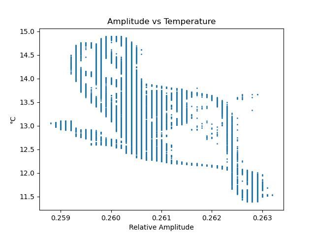
                                      As an aside I graphed Amplitude vs Temperature and drew a Possum on a branch:

                                      0502ampvstemp.jpg

                                      The vertical stripes are due to mathematical rounding between sensor and graph. Otherwise the graph shows amplitude broadly increases as temperature falls but the effect isn't precise. No idea what causes the horizontal gaps.

                                      Dave

                                      #632114
                                      John Haine
                                      Participant
                                        @johnhaine32865

                                        Dave, don't despair, those errors could be in part due to NTP wandering at your location…

                                        **LINK**

                                        #632123
                                        S K
                                        Participant
                                          @sk20060
                                          No idea what causes the horizontal gaps.

                                          Dave

                                          Your data in X starts with integers? The horizontal data looks to be quantized in units of 0.0001. So either the horizontal gaps are the natural result of starting with integer data, or there's rounding to 0.0001 units in the X axis as well?

                                          #632154
                                          duncan webster 1
                                          Participant
                                            @duncanwebster1
                                            Posted by duncan webster on 05/02/2023 10:00:10:

                                            Posted by John Haine on 05/02/2023 08:45:16:

                                            It does, but receiving it and synching a micro to it doesn't seem to be so easy. Do you know of any low cost receivers Duncan please? I have tried receiving dcf77 using a module recovered from a cheap weather station but without success.

                                            I bought one off ebay for very little. I used it to pulse a slave clock as it had a square wave 1 second on one second off output. I took it out eventually as when anthhorn was down for maintainable the clock went doolally. I'll have a search later on, if I can find it you can have it. With a software event timer you could count ticks per 2 seconds from the OCXO.

                                            This is on ebay, cheaper from China, but unless I'm missing something it doesn't have the 1 second on/off pulse, so might be more difficult to use. I think you'd have to unscramble the data, as the 60kHz is switched on and off to send the data. Loads of info on web about this. However, the good news is I've found mine. It has a much smaller aerial, but got good signal in NW England. If you want it send me your dirt mail address via email

                                            #632156
                                            Michael Gilligan
                                            Participant
                                              @michaelgilligan61133

                                              [ Addendum ] __ For clarity:

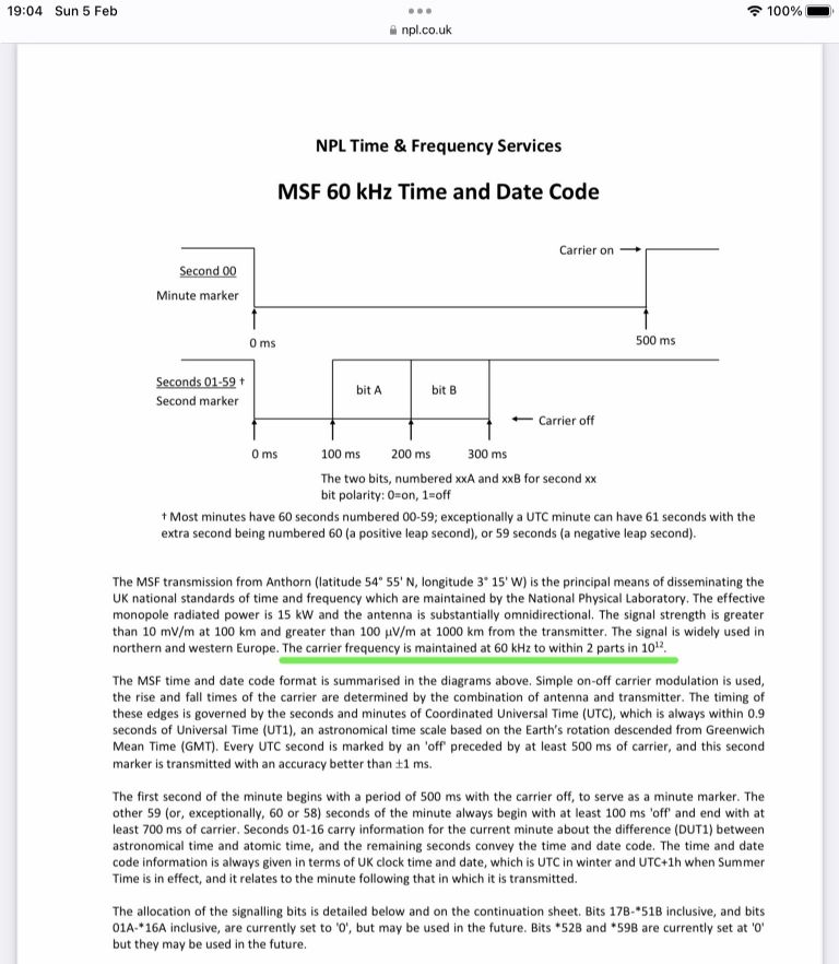
                                              9a77e99e-56cf-42f8-8d09-26edc87493ba.jpeg

                                              .

                                              Ref. __ **LINK**

                                              https://www.npl.co.uk/products-services/time-frequency/msf-radio-time-signal/msf_time_date_code

                                              .

                                              I think, therefore, it may be the carrier frequency that would be most useful in the present context, rather than the time signals.

                                              .

                                              MichaelG.

                                              #632158
                                              S K
                                              Participant
                                                @sk20060

                                                The 60 kHz carrier turns off and back on once per minute, and so can't be relied on as a continuous source, if that's your hope.

                                                #632160
                                                Michael Gilligan
                                                Participant
                                                  @michaelgilligan61133
                                                  Posted by S K on 05/02/2023 19:58:13:

                                                  The 60 kHz carrier turns off and back on once per minute, and so can't be relied on as a continuous source, if that's your hope.

                                                  .

                                                  … and it also turns off at other times

                                                  That was the point of my previous post, at 09:48:08

                                                  MichaelG.

                                                  Edited By Michael Gilligan on 05/02/2023 20:16:02

                                                  #632162
                                                  duncan webster 1
                                                  Participant
                                                    @duncanwebster1

                                                    But if you unscramble it you can get pulses at 1 second intervals, which is what my receiver does, and they are very accurate seconds, so you can use it to calibrate / adjust an OCXO. The fact that it goes off for maintainence is irrelevant, just don't calibrate at that time, they publish in advance.

                                                    #632164
                                                    Michael Gilligan
                                                    Participant
                                                      @michaelgilligan61133

                                                      Sorry, Duncan …

                                                      Yes I understand how it works … I have several MSF clocks.

                                                      I was just wondering if the 60kHz carrier frequency itself was a more useful reference for calibrating or disciplining milliseconds.

                                                      MichaelG.

                                                    Viewing 25 posts - 351 through 375 (of 562 total)
                                                    • Please log in to reply to this topic. Registering is free and easy using the links on the menu at the top of this page.

                                                    Advert

                                                    Latest Replies

                                                    Viewing 25 topics - 1 through 25 (of 25 total)
                                                    Viewing 25 topics - 1 through 25 (of 25 total)

                                                    View full reply list.

                                                    Advert

                                                    Newsletter Sign-up