Experimental Pendulum Clock
Experimental Pendulum Clock
Home › Forums › Clocks and Scientific Instruments › Experimental Pendulum Clock
- This topic has 561 replies, 22 voices, and was last updated 27 February 2023 at 22:17 by
duncan webster 1.
-
AuthorPosts
-
18 January 2023 at 09:10 #629942
 Michael GilliganParticipant@michaelgilligan61133Posted by duncan webster on 17/01/2023 22:59:31:
When I went to SOD's link the cupboard was bare. Said 'this item has been deleted'. Any clues?
[…]
.
Same here … and the rest of the message is: You might be able to find it in your deleted files. If it's not there, try asking the person who shared it with you.
So … Hello, Dave; where is that file, please ?
MichaelG.
18 January 2023 at 09:52 #629948John Haine
Participant@johnhaine32865Posted by duncan webster on 17/01/2023 22:59:31:When I went to SOD's link the cupboard was bare. Said 'this item has been deleted'. Any clues?
According to leapsecond.com you can drive a picpet with 20 Mhz, no intention of going back to pics, they made my head hurt, and that was 10 years ago at least
Edited By duncan webster on 17/01/2023 23:05:38
I found the file OK.
If you have a pre-programmed PIC you just use it as a component, no sweat.
18 January 2023 at 10:08 #629957SillyOldDuffer
Moderator@sillyolddufferPosted by Michael Gilligan on 18/01/2023 09:10:46:Posted by duncan webster on 17/01/2023 22:59:31:When I went to SOD's link the cupboard was bare. Said 'this item has been deleted'. Any clues?
[…]
.
Same here … and the rest of the message is: You might be able to find it in your deleted files. If it's not there, try asking the person who shared it with you.
So … Hello, Dave; where is that file, please ?
MichaelG.
My fault, though I didn't know changing a Dropbox file would invalidate the link!
After publishing the link I noticed the code was configured to use an external clock, which needs an oscillator connected to Pin D5. Line 37:
#define EXTERNAL_CLOCK
This is an advanced option, and the default should be to use the internal 16MHz oscillator. So I changed Line 37 to:
#define NO_EXTERNAL_CLOCK
This is the latest download link. John probably downloaded the EXTERNAL_CLOCK version before I changed it.
Fingers crossed Dropbox works and also the bug I found last night fixed my weird stepping problem.
This morning's job is to graph the overnight run to confirm the clock is reporting properly now, without glitches.
If fixed I can get back to improving time keeping. Lots to do in that department. I know the existing temperature and pressure compensations aren't quite right and want to try the multi-variable compensation John H helped me to get. As soon as the software is working properly, I need to make a better suspension incorporating the mechanical improvements received a few weeks ago. And then maybe a Tungsten loaded spherical bob!
Also occurred to me that the Infrared beam could be replaced with a laser. IR beams are broad, and I've done nothing to collimate mine. The sensor is almost certainly receiving a noisy signal that adds uncertainty to period measurements. Improving this with a lens or slit has long been on the list but maybe a laser is easier and better. Laser modules like the KY-008 produce sharply defined narrow beams, and can be had for under £5 (Much less direct from you know where!)
Dave
Edited By SillyOldDuffer on 18/01/2023 10:13:26
18 January 2023 at 10:52 #629977 Michael GilliganParticipant@michaelgilligan61133
Got it … thanks, Dave
ardPET sounds like a Pit-Bull

MichaelG.
18 January 2023 at 11:00 #629981 Michael GilliganParticipant@michaelgilligan61133
Posted by SillyOldDuffer on 18/01/2023 10:08:27:
[…]
Also occurred to me that the Infrared beam could be replaced with a laser. IR beams are broad, and I've done nothing to collimate mine. The sensor is almost certainly receiving a noisy signal that adds uncertainty to period measurements. Improving this with a lens or slit has long been on the list but maybe a laser is easier and better. Laser modules like the KY-008 produce sharply defined narrow beams, and can be had for under £5 (Much less direct from you know where!)
.
Good thinking, Dave … and when everything else is sorted, ask me about ‘Spatial Filtering’
[ not now … we don’t want you getting distracted ]
MichaelG.
18 January 2023 at 11:44 #629992John Haine
Participant@johnhaine32865I did some measurements on opto interrupters and posted some results here – can't immediately find it but could send a copy of the full article. Basically you can get sub-micron sensing of a pin or vane on the end of the rod.
18 January 2023 at 12:09 #630002SillyOldDuffer
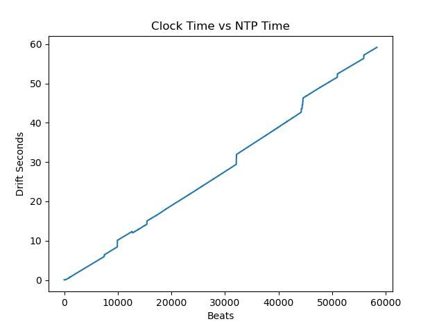
Moderator@sillyolddufferWoe, woe and thrice woe! The step problem is still unfixed:
A straight line rising diagonally from 0,0 is fine, because steady drift at the same rate is easy to fix. Step jumps are unacceptable, and in my case they are all associated with mangled data:
12735 13240093 0.2605 0.3600 28 981.84 0.00 9.74 824447 1674000470 843515 1674000458 800457 0.006643000000000399
15457 5079547 0.0000 0.3600 28 982.08 0.00 9.33 824446 1674002714 987039 1674002700 289264 -0.5089489999999994
15458 8170408 0.0000 0.3600 28 982.08 0.00 9.33 824446 1674002715 811485 1674002700 798200 -0.31550999999999974Beat number 12735 has been reported as bad because it's over 5mS different from the previous tick. But it's not corrupt: a period of 13240093 isn't too far off the average 13206989, and an amplitude of 0.2605 is OK too.
However, beats 15457 and 15458 are both obviously wrong and they cause gross reporting delays of -0.5089s and -0.3155s. A jump of nearly 1 second. Interestingly the clock reports the time correctly, and the step occurs because the report takes tenths of seconds to get from Arduino to RaspberryPi. The data corruption and delay are both clues!
Dave
18 January 2023 at 12:45 #630006duncan webster 1
Participant@duncanwebster1Posted by John Haine on 18/01/2023 11:44:47:I did some measurements on opto interrupters and posted some results here – can't immediately find it but could send a copy of the full article. Basically you can get sub-micron sensing of a pin or vane on the end of the rod.
And if you choose the right one they incorporate a schmidt trigger, so no bounce
18 January 2023 at 13:48 #630019John Haine
Participant@johnhaine32865Specifically this one: **LINK**
Also available from various hobby suppliers, also with a small breakout pcb. The first lot of optos I bought though came as a pack of 10 for not a lot of money on eBay, each on a pcb with a comparator "buffer" – they were quite useless as the comparator hooted at each transition.
21 January 2023 at 14:16 #630476SillyOldDuffer
Moderator@sillyolddufferAnother lack of progress Progress Report. I've been busy eliminating possible causes of the stepping problem, and am now 99% sure the issue is in my Arduino code or maybe the board.
I've confirmed it's not caused by the RaspberryPi or the software I wrote to read and timestamp data sent by the Arduino. It's not due to the time taken by the Humidity Sensor, and is unlikely to be due to I2C or the other sensors. Nor caused by the over-complicated way I was counting ticks, variable or buffer overflow, misused pointers, or a run-time memory shortage.
I've got one other software possibility to try, then I''ll swap the Arduino board. Could be a hardware problem, like a dry-joint glitching, or an intermittent plug contact. If so, it's the first time an Arduino board has failed me. Whatever the cause, I've not been able to replicate it on my dining table.
As a positive, I've learned more about the accuracy of Linux clocks. Although Linux provides nano-second timers, they're only accurate between 150 and 15uS, presumably depending entirely on the underlying hardware. My raspberryPi3B isn't completely accurate below about 0.2mS, whilst my Intel workstation isn't reliable below about 20uS. Also, NTP time is 10x worse on the raspberry than the workstation, probably because the raspberry gets internet time via Wifi, an extra stage compared with the hardwired workstation.
Linux is good for long-term accuracy – always accurate within tens of milliseconds – but highly inferior to a microcontroller for sub-millisecond accuracy, precision and resolution.
Dave
24 January 2023 at 12:27 #630833SillyOldDuffer
Moderator@sillyolddufferNow I'm thoroughly confused!
Last night I gave up on the stepping problem, whereby every so often my clock apparently jumps compared with Network Protocol Time:
It doesn't really jump – the problem is something wrong in the logging software, written by me. Wasted days trying to fix it with no success. Anyway, noticing that apart from the steps the graph line shows my clock drifts fast compared to NTP by a more-or-less constant rate, I decided to fix that.
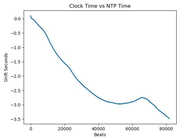
The clock software already compensates (imperfectly) for temperature and pressure, so I added the code necessary to compensate for constant drift, recompiled, and restarted a new log, resulting in:
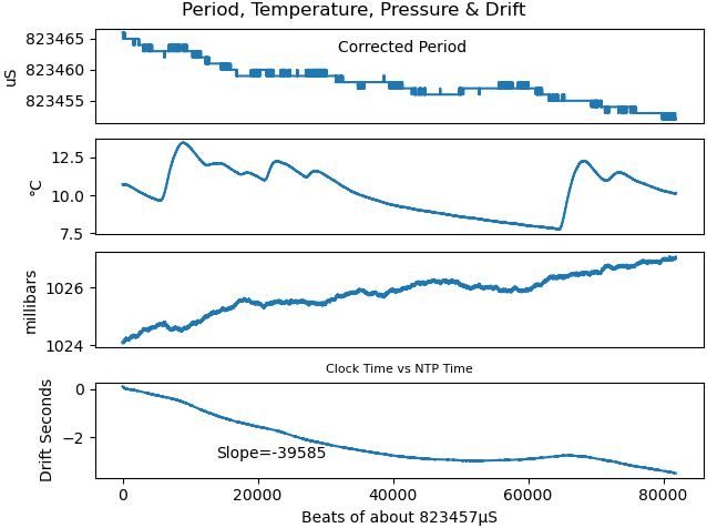
Though still not right, this is much better. The clock is now slow by 3.5 seconds (in 19 hours) rather than 65 seconds fast. However, whilst the drift compensated graph is nearly straight, it bumps upwards at about 65000 beats. This I think correlates to a drop in air pressure followed by a rapid rise in temperature, see below:
Not worried much because I already know the way I compensate for temperature and pressure combined is flawed. Although the maths in the clock is better than not bothering, the clock is still obviously sensitive to temperature and pressure change. (Obviously sensitive to statistical analysis, not the human eye!) Thanks to John H, I have the analytical method needed to produce the numbers required to improve the clock's compensation, fingers crossed.
Two new mysteries! Although I only made a simple addition to the code, with no obvious relationship to the stepping problem, last night's run was perfect – there are no incorrect steps in the log. Good news except I don't like problems that fix themselves by magic. Probably still lurking in the undergrowth waiting to bite me again.
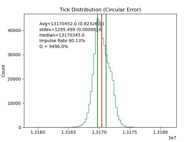
Also odd is the Q measurement and underlying tick distribution. Normally I get a spike graph like this example:
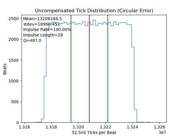
Not so, last night the Q apparently fell from about 9500 to 487, due to the period measured in ticks falling almost equally across a range, an unnatural distribution:
Might be another software problem. Has to be investigated. More work!!!
Previously I'd have blamed this abnormality on disturbing the physical clock in order to upload new software. Except for nearly a month I've been able to upload new software , and reconfigure various values, without going anywhere near it. The clock and logging raspberryPi are upstairs, whilst I do all the analysis, code changes and testing in my dining room. As I talk to the raspberry via my home network, the pendulum is only disturbed when the clock is restarted, and that's automatic. I've eliminated clumsy me as a source of error.
Dave
Edited By SillyOldDuffer on 24/01/2023 12:33:58
24 January 2023 at 19:53 #630871SillyOldDuffer
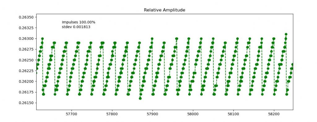
Moderator@sillyolddufferAnother mystery from last night's run. Amplitude varies predictably even though there's a constant impulse on every beat. Zooming in:
Relative amplitude appears to rise from about 26.175% to about 26.28% in 22 consistent steps and then drop back. Given the pendulum is getting an accurate constant impulse I would expected amplitude to vary randomly about the mean. I've no idea what would cause a zigzag, yet there it is! Almost as if amplitude builds up until something gives way and releases the energy with a bump. Most odd.
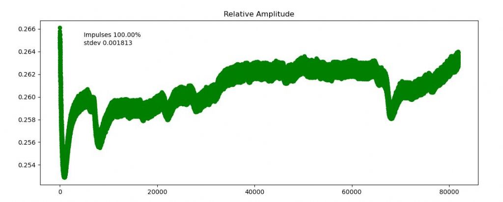
Relative Amplitude varies strangely over the long run too. Not by much, less than 1 part per thousand, but the graph shows something effects it. Possibly temperature. Dunno.
Why is nothing ever easy?
Dave
Edited By SillyOldDuffer on 24/01/2023 19:53:59
25 January 2023 at 11:27 #630905SillyOldDuffer
Moderator@sillyolddufferI left the clock logging overnight without making any changes:
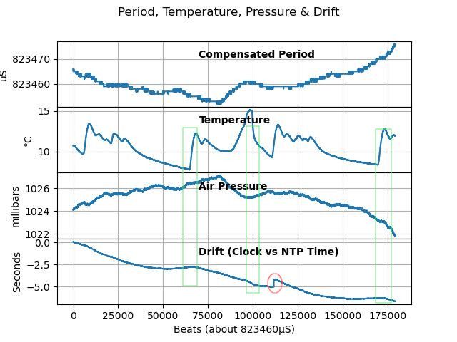
Whatever was causing step jumps has stopped. There's only one jump, circled in red, and checking the log shows it's different. The step jump errors that caused so much grief were obvious data corruptions associated with malfunction of the serial data link. Something truly nasty. The single example in last night's run is consistent with a sensor error. The step is due to the clock reporting two beats, when there was only one. The Arduino counter-timer reported a period lasting 3587640 cpu ticks, followed by a second period of 9708108 ticks. These add up to 13295748 which though high suggests a normal tick was miscounted, cause unknown.
Looking at the Drift graph (Clock vs Network Protocol Time), the line confirms a constant drift amounting to a little under 37 microseconds per beat, which I can correct without stopping the clock. (If the new code works properly!)
The bumps in the line, highlighted in the Green boxes above, look to be associated with temperature change. The relationship isn't obvious because air pressure and temperature both effect pendulum period and can compensate or reinforce each other. But the biggest bump (leftmost green box, around beat 63000), aligns with temperature and pressure rising together.
That my compensation is wonky is fairly obvious from the graphs. Although Compensated Period is mostly temperature corrected, it follows air-pressure changes almost exactly. The maths is wrong, so that's the next job. Whilst rewriting the software, I'll let the clock run with a further 37uS drift correction to see how close it stays to NTP time.
Just to be clear, the clock is running independently. The pendulum isn't being time corrected by the Arduino quartz crystal or GPS. Instead it counts average period in microseconds compensated for temperature and air pressure, albeit imperfectly. That causes a new problem! Counting in microseconds is flawed because it limits average period precision to ±1uS. Will switch to counting in tenths of uS or Nanoseconds later, if the pendulum performs well enough to justify improved counting.
Dave
26 January 2023 at 10:51 #631008S K
Participant@sk20060A few things come to mind:
First, I believe you are only using a single position sensor (e.g. an opto-interrupter), right? In that case, how are you measuring the "relative amplitude?" Calculated from slight changes in period?
I believe you are also applying an impulse on every swing. Are you absolutely sure that the impulse width is exactly the same every time, and not off by +/- your clock period? If not, your variation in amplitude may be due to a beat-like phenomena. Maybe that 64ns or whatever your timing resolution is can be found in your data? For example, if the interrupt signal (or something similar) cannot be detected or acted on to better than 64 ns resolution, then the width of the pulses can vary slowly between x and x+64 (or x-64) ns and then flip back to x?
Stepping back, I think you should consider switching to a two-sensor arrangement (e.g. using those Sharp sensors): one for the bottom dead center (where the impulse should be applied) and one for an extremity of the swing.
I'm not sure it's a good idea to be applying an impulse every swing. That requires a finely-balanced impulse that can maintain a certain swing amplitude just based on the strength of the impulses alone. That's difficult to maintain, and I suspect that's leading to some of your trouble as in the "relative amplitude" graph. Instead, it should be applied only when the swing fails to reach the extremity-sensor. The impulse should then be just strong enough to cause the swing to exceed the extremity sensor for some number of swings, like say 30 on average. That way, the strength of the impulse is not critically important, it just has to be "strong enough" (though everything will eventually be found as flaws in the data if you look close enough!). You might choose to note or exclude the impulsed swing from your data, as it probably causes a non-ideal swing.
Edited By S K on 26/01/2023 11:09:10
26 January 2023 at 12:33 #631027SillyOldDuffer
Moderator@sillyolddufferPosted by S K on 26/01/2023 10:51:00:A few things come to mind:
First, I believe you are only using a single position sensor (e.g. an opto-interrupter), right? In that case, how are you measuring the "relative amplitude?" Calculated from slight changes in period?
I believe you are also applying an impulse on every swing. Are you absolutely sure that the impulse width is exactly the same every time, and not off by +/- your clock period? If not, your variation in amplitude may be due to a beat-like phenomena. Maybe that 64ns or whatever your timing resolution is can be found in your data? For example, if the interrupt signal (or something similar) cannot be detected or acted on to better than 64 ns resolution, then the width of the pulses can vary slowly between x and x+64 (or x-64) ns and then flip back to x?
Stepping back, I think you should consider switching to a two-sensor arrangement (e.g. using those Sharp sensors): one for the bottom dead center (where the impulse should be applied) and one for an extremity of the swing.
I'm not sure it's a good idea to be applying an impulse every swing. That requires a finely-balanced impulse that can maintain a certain swing amplitude just based on the strength of the impulses alone. That's difficult to maintain, and I suspect that's leading to some of your trouble as in the "relative amplitude" graph. Instead, it should be applied only when the swing fails to reach the extremity-sensor. The impulse should then be just strong enough to cause the swing to exceed the extremity sensor for some number of swings, like say 30 on average. That way, the strength of the impulse is not critically important, it just has to be "strong enough" (though everything will eventually be found as flaws in the data if you look close enough!). You might choose to note or exclude the impulsed swing from your data, as it probably causes a non-ideal swing.
Thanks SK, good points, and I find it helpful to explain. It's so easy to get into a mental rut where fixed ideas and unchallenged assumptions cause endless bother.
Yes, it's a single-sensor, deliberately offset to remove ambiguity about which way the pendulum is swinging. Period is measured as the time between FALLING events (i.e time between bob blocking the beam).
'Relative amplitude' is the time between FALLING and RISING, that is how long the beam is blocked by the bob as it sweeps past the beam. I propose the ratio between Period and Blocked is proportional to amplitude because pendula aren't isochronous – their period varies slightly with amplitude. I appear to be able to detect this with a microcontroller. Seems to work in practice, even though the latest amplitude results are odd!
Impulses are triggered by FALLING events. The bob swings into the beam towards a side-mounted electromagnet. I can trigger the magnet at any time after the FALLING event, and began with the unconventional idea of lifting the bob gently above the end-of-swing point to counter gravity and then impulsing by dropping it. Although this didn't obviously disturb the bob, it's fiddly to get right, and had no obvious advantage. So I reverted to impulsing the bob immediately on each FALLING event. More conventional, the bob is closer to BDC and still travelling quite quickly, so less likely to be disturbed – in theory. Works just as well and is much easier to set up.
As the clock is able to measure amplitude, at first it was programmed to impulse only when the amplitude fell below a certain level – huff and puff governed impulses. Tried various combinations, at one extreme only impulsing once per 100 beats, and at the other impulsing on every beat. Impulse power can be varied accurately to do either.
Once per 100 beats seemed smart because the pendulum swings freely, undisturbed most of the time. But once per 100 beats a hefty impulse is needed to keep the clock going, and it shows up in the data. I've found less evidence of disturbance by impulsing lightly on every beat, and this also keeps the pendulum more regular because each swing is more-or-less of constant amplitude. In this mode, the governor is off and impulse power was set manually to be just strong enough to keep the pendulum swinging.
So far the pendulum has been maintained with constant length impulses but I could try governing it by varying impulse length rather than huff and puff on/off methods. Should be finer grained and less disturbing to the bob.
Impulse power is accurately controlled by a hardware timer that's almost independent of whatever else the microcontroller is doing. The magnet pulse can be any length from 0 to 4.096mS in steps of 0.016mS. So yes, I'm certain the impulse length is accurate – it's driven by CPU clock ticks, which come from a 16MHz quartz crystal oscillator, somewhere in the 20ppm region.
I don't claim that anything in my approach is wonderful or going to change the way pendulum clocks are made. It's just fascinating to explore what works and what doesn't, especially if it's a shade maverick!
I like your beat phenomena suggestion – I'd never have thought of that, and don't have any suggestions of my own. I think I can test it on my dining table with an oscilloscope and signal generator. Got to go out this afternoon. Most frustrating, I want to try it!
Ta
Dave
26 January 2023 at 15:39 #631039S K
Participant@sk20060After I posted I wondered some more about the difference between impulses on every beat vs. every n beats.
The synchronome-type clocks only impulse based on the retardation of the swing below a trigger level. But it's via a messy mechanical detection and impulse scheme, and I could see them wanting to minimize the frequency of doing that. Your essentially frictionless optical and electromagnetic version shouldn't suffer much from that.
And of course ordinary clocks do impulse on every beat. I'd expect clock makers would have devised n-beat impulse schemes long ago if that was really superior.
Anyway, so now I'm doubtful that a 1 beat impulse is better or worse than an n-beat one. But what I did think is that a scheme which skips the impulse-beats and somehow counts time only on the non-impulse beats could be superior. That would naively be hard to measure time from, but in hybrid mechanical / computational system, all kinds of magic can happen.
If I were you, I'd stop thinking of your measurements as "amplitude" and just call it what it is: "period." Yes, I know it's related, but you aren't actually computing the amplitude (e.g. in degrees) from period, are you? You are just measuring and plotting the period.
I still think there's some beat-type situation going on. I can totally see ~22 x ~3ns errors adding up to 64 ns and then starting over somewhere in your system.
26 January 2023 at 16:57 #631049duncan webster 1
Participant@duncanwebster1Pedant alert! Synchronomes and Pulsynetics impulse every 30 seconds via a gravity escapement, PO type 36,which were made by quite a few manufacturers, used Hyp toggle and magnetic impulse when amplitude decayed.
26 January 2023 at 17:45 #631055S K
Participant@sk20060Some used a ratchet-like system to time the gravity-driven impulse, e.g. every 30 seconds exactly by counting swings, and others used the Hyp toggle, whose timing is variable based on the amplitude of the swing.
All those that I've seen used a gravity "escapement" (used loosely), with the lever reset electromagnetically. I haven't seen a direct magnetic impulse (no gravity escapement) on any of the original historic models. I've wondered why, or maybe I have just missed them?
It's surprising how well those old systems worked despite the mechanical impulses. One would hope that a modern "frictionless" interpretation would do better. Of course, it's all just for fun and satisfaction these days.
(I love being pedantic too!)
Edited By S K on 26/01/2023 17:49:17
26 January 2023 at 17:47 #631056SillyOldDuffer
Moderator@sillyolddufferPosted by S K on 26/01/2023 15:39:52:
…
Anyway, so now I'm doubtful that a 1 beat impulse is better or worse than an n-beat one. But what I did think is that a scheme which skips the impulse-beats and somehow counts time only on the non-impulse beats could be superior. That would naively be hard to measure time from, but in hybrid mechanical / computational system, all kinds of magic can happen.
If I were you, I'd stop thinking of your measurements as "amplitude" and just call it what it is: "period." Yes, I know it's related, but you aren't actually computing the amplitude (e.g. in degrees) from period, are you? You are just measuring and plotting the period.
I still think there's some beat-type situation going on. I can totally see ~22 x ~3ns errors adding up to 64 ns and then starting over somewhere in your system.
In reverse order, I've been through the logic looking for an integer rounding effect. I'm using binary arithmetic for efficiency and 'relative amplitude' is calculated in micros(), an Arduino time function that increments in 4uS steps. No joy with that so far. I'm about to try altering the impulse power, ie pulse length, to see if it changes the waveform. Might prove it's a beat effect.
I'm calling it 'relative amplitude' because, though derived from period, it's not period. And I'm already using period to name the real one measured in 62.5nS ticks. 'relative amplitude' is a comparator rather than a accurate measurement, just a way of indicating is rising or falling. A bit of maths acts (I hope!) as a kind of digital filter because period measured in 62.5nS ticks is rather noisy, making it difficult to reliably detect decay directly. At the moment the measurement isn't used for anything because the impulse was set manually. It becomes important if I go back to actively governing impulses.
I don't know if constant impulsing vs free swinging is better or worse either! From memory Shortt-Synchronomes are intermittently pulsed once every 30 seconds or so, whilst Riefler clocks are impulsed on every beat. Possibly the difference is due to the mechanical difficulties of impulsing when the clocks were built. Maybe Shortt did better by free swinging because his impulses were a bit rough and were less disturbing when done infrequently. Riefler came up with a more delicate impulse system, and maybe did better by impulsing gently on every beat.
Your idea of not counting abnormal beats is what my clock does to an extreme. It doesn't care what the pendulum period actually is, instead average period at the current temperature and pressure is counted.
In stage one the pendulum's performance is measured by collecting period, temperature and pressure over a long time. The data is statistically analysed, giving me the mean period at any given temperature and pressure. In stage two, the clock just counts unmeasured ticks, it being assumed that the oscillator is operating within it's normal statistical range. This variations in mechanical performance are filtered out, and, provided the pendulum ticks normally, the clock should keep good time. Ideally the pendulum should have a low standard deviation, with sensitive temperature and pressure sensors, and only need small compensations.
Dave
26 January 2023 at 18:06 #631060S K
Participant@sk20060Also: If you have an oscilloscope, I'd put it on long or infinite persistence and see if any of the waveforms that should be uniform aren't.
I wish I could find good quality drawings or photos of the Riefler pivoting spring mechanism. I guess I could look up his old patent.
26 January 2023 at 20:10 #631064S K
Participant@sk20060It's amusing to think about all the corrections that can be made to a pendulum based on sensors and math, some of which has been discussed and implemented in this thread: temperature and humidity at the least.
It's even likely possible to "discipline" a pendulum such that its motion precisely matches a GPS pulse-per-second signal, for example by adjusting the amplitude via a PID controller to take advantage of its slightly non-isochronous behavior. That reduces it to an "executive toy," but it's a fun idea.
Mine will not be a second's pendulum, so I figured I'd just rate it mathematically by comparing it to a precise RTC over a reasonably-long time period, e.g. a week or so. Ticks would be in floating-point rather than integers, or else if one felt the need for integer seconds, they could be generated by interpolation.
Of course, it's then tempting to correct it daily, or hourly, or even continuously. Is that any different from someone with a fancy new mechanical watch who obsessively monitors and corrects it every day?
In an age of atomic clocks, we are all just making "executive toys." 😀
Edited By S K on 26/01/2023 20:13:03
26 January 2023 at 22:04 #631070duncan webster 1
Participant@duncanwebster1I don't think it is difficult to come up with an expression relating period to pendulum length, temperature and air density (this is affected by temperature, pressure and humidity). This I'm sure will involve a sqrt, so attempts to fit a linear regression might be compromised. I would imagine over the years someone has done this, but if not I'll have a go. Always better to fit experimental data to a curve which has the correct shape. Don't try to baffle me with statistics, it won't mean anything to me!
29 January 2023 at 12:34 #631259SillyOldDuffer
Moderator@sillyolddufferLast night's run was "quite interesting".
The clock is keeping it's own time, whilst logging actual period, clock-time, temperature and air pressure to a raspberryPi that timestamps each log entry.
Whilst debugging other faults, I've added to the number of commands I can send to configure the clock's software on the fly. As well as logging, the clock obeys commands received from the raspsberryPi, and the raspberryPi can be sent clock commands from any network connected computer in my home.
The commands are:
* U unixtimestamp – set time in seconds since 00:00:00 1/1/1970
* P pressureCoef – set pressureCoefficient arrives as n * 1000
* T tempCoef – set tempCoefficient arrives as n * 1000
* I impulse – set impulse, up to 255 in 8uS steps.
* A amplitude – set threshold, 0.0 – 1.0 where 3456 = 0.3456
* C,c n – Turn compensation on/off. Any n
* D n – set constant drift compensation
* R n – Reset Arduino (and clock). Any n.
* X n – xtal frequency in Hz for tick to second conversionSo without physically touching it I can set the clock in flight to NTP time switch compensation ON/OFF, alter the pressure and temperature compensation coefficients, compensate for steady drift, change impulse power, and restart the clock.
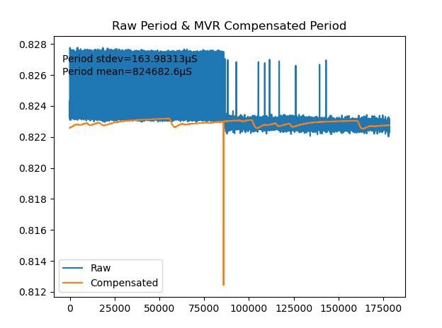
Yesterday's log showed clear evidence of over impulsing, and a steady drift. So at beat 86380, I sent the commands needed to reduce impulse from '28' to '20', and to compensate for the steady drift.
Result this morning:
On the left, period in blue shows many spikes (actually about 1 in 30). On the right, after impulse power was dropped, the number of spikes is much lower. Conclusion: over impulsing was disturbing the pendulum, and might be good to drop the impulse a little lower.
The orange line is period corrected by the clock compensating for temperature and pressure using values obtained by applying multivariable regression to previous statistical data. Not quite right because the line visibly bumps when my central heating comes on morning and evening. The error is partly because the regression was applied to only 18 hours of data, when it should be at least a week's worth, ideally more, and partly because changing impulse changed period, so the earlier period/temp/pressure relationships are skewed.
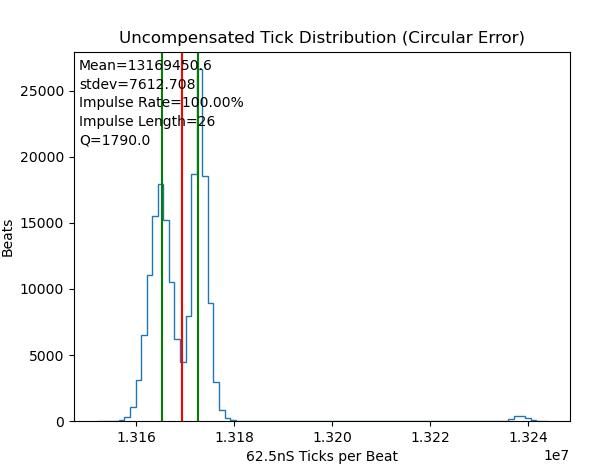
Reducing impulse had an obvious effect on Q too:
Three peaks! The first and third (at 1.324) are from the strong impulse, the second from the weaker. Changing impulse power altered the pendulum's period, or, in old-fashioned parlance, 'the pendulum was dominating the clock', not good. Impulsing too powerfully shifts the period slightly, reduces Q, and – in this clock – creates a second mode of oscillation at about 13240000 ticks per beat.
Improved Q is visible in the second reduced impulse peak, because it'is taller and sharper than the first. Overall Q has dropped to 1790 on the graph because the data covers a shift in frequency. Earlier runs showed Q approaching 10000, which is good for an ordinary pendulum, but on my clock only if the pendulum isn't over impulsed, and it's sensitive. The effect of over impulsing is probably worse in my pendulum because the bob is very light. Less than 30g, compared with the usual few kilograms in pendulum bobs.
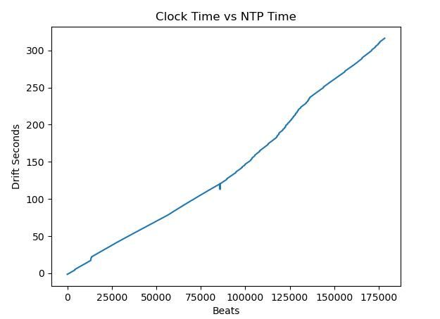
Annoying mistake, I got drift correction wrong by entering the correct number with the wrong sign, making drift worse:
Slightly worrying is drift appears to have become less constant after reducing impulse. More to do.
Dave
Edited By SillyOldDuffer on 29/01/2023 12:34:49
29 January 2023 at 16:37 #631275Alan Wood 4
Participant@alanwood4There was a recent article in HJ where the author was moving the CoG of the pendulum and hence the timing by moving weights up and down a church clock pendulum with a stepper motor. This was done within a control loop. The idea appealed as it did not need modification of the clock mechanism and could easily be removed. Weight trays are quite common on church clocks. There are strict rules what you can and cannot do to such installations.
I then found this which would be much easier to implement. The author (at CERN) simply winds a ball chain up and down into the weight tray with a stepper motor, again within a control loop. Beautifully simple and elegant.
Edited By Alan Wood 4 on 29/01/2023 16:38:32
30 January 2023 at 12:51 #631350SillyOldDuffer
Moderator@sillyolddufferCouple of blunders yesterday:
- Reduced impulse power too much and the clock stopped.
- Tested Drift compensation and it didn't work – wrong numbers. Operator error! Turned out to be because my data analysis program calculates compensation is microseconds. whilst the clock compensates in units of about 62.5nS, and converts to microseconds later. Right and left hand failed to communicate!
So restarted last night with a little more impulse oomph, and after realising the drift correction unit was wrong, put in a better number. A step in the right direction – the code is working:
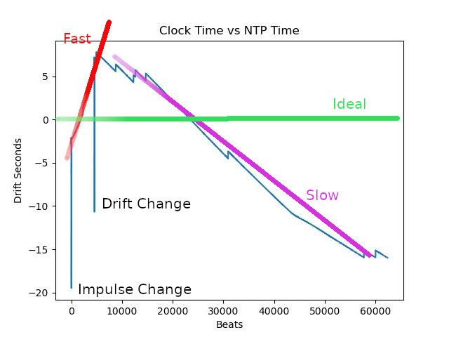
The graph shows shortly after the clock started, I increased the impulse, first down spike. The clock then ran fast – red line – compared with Network Protocol Time until I changed the drift compensation at about beat 5000, after which the clock runs slow – purple line.
Still not correct – the target is a flat horizontal line on zero – the green line
Just now, the statistics told me error overnight was 208.24uS per beat, so I have to tell the clock to compensate by +3332 ticks of about 62.5nS each. I shall issue the necessary command now and see what happens.
dave@condor:~/devel/python$ nc dove3b 11111
D 3332
OK D 3332 65347'nc' is netcat, described as the Swiss Utility Knife of network commands! It connected me to port 11111 on the computer 'dove3b', and let me send the command line 'D 3332'.
dove3b is the raspberryPi computer connected to the Arduino that runs the clock. It's also wifi connected to my home network.
A program written by me on dove3b writes everything it receives from the clock to a log file. It also listens on port 11111 for network requests, and forwards any received to the clock. The program tells nc it got the command correctly by echoing it back with an OK. 65347 is the beat number at which the change was made.
Don't bet the farm on this latest correction achieving a green horizontal line showing zero drift!
Meanwhile, I've identified another problem with my statistical strategy; the weather!
Previously, weather's been delightfully changeable with plenty of big temperature and air-pressure swings. Lots of change are just what's needed to identify correlations, whilst settled weather doesn't provide good data. The statistics have nothing to work on unless temperature and air pressure in the dataset change significantly. It means I have to collect a lot more beat data at he moment before trusting an analysis intended to identify the perfect compensation between drift, temperature and air-pressure.
Dave
-
AuthorPosts
- Please log in to reply to this topic. Registering is free and easy using the links on the menu at the top of this page.
Latest Replies
Home › Forums › Clocks and Scientific Instruments › Topics
-
- Topic
- Voices
- Posts
- Last Post
-
-
All things Beaver Mill
1
2
…
8
9
Started by:
Robert James 3 in: Manual machine tools
- 42
- 206
-
1 July 2025 at 13:57
Swarf Maker
-
Speed camera
Started by:
 David George 1
in: The Tea Room
- 1
- 1
-
1 July 2025 at 13:25
 David George 1
-
Firth Valve Gear
Started by:
Andy Stopford in: Traction engines
- 9
- 18
-
1 July 2025 at 12:59
Nigel Graham 2
-
Help for DIY lathe build.
1
2
Started by:
moogie in: Help and Assistance! (Offered or Wanted)
- 16
- 30
-
1 July 2025 at 12:26
Pete
-
M type top slide conversion??
Started by:
jimmyjaffa in: Beginners questions
- 7
- 11
-
1 July 2025 at 11:35
 David George 1
-
Dial test indicator vs Dial indicator
Started by:
martian in: Workshop Tools and Tooling
- 14
- 21
-
1 July 2025 at 11:25
Pete
-
Request for a Slot to be Milled in a Shaft
Started by:
James Alford in: Help and Assistance! (Offered or Wanted)
- 9
- 17
-
1 July 2025 at 10:47
James Alford
-
Offen screw type telescopic gauge.
Started by:
Graeme Seed in: Workshop Tools and Tooling
- 4
- 9
-
1 July 2025 at 10:41
Graeme Seed
-
Bearing boxes for ball race
Started by:
Paul McDonough in: Beginners questions
- 9
- 15
-
1 July 2025 at 09:41
Zan
-
Twin Engineering’s heavy mill/drill quill removal
Started by:
Martin of Wick in: Manual machine tools
- 7
- 8
-
1 July 2025 at 09:35
Clive Foster
-
2 Machine lights
Started by:
modeng2000 in: Workshop Tools and Tooling
- 2
- 6
-
1 July 2025 at 08:57
Dalboy
-
IME Watchmakers lathe
Started by:
Greensands in: Manual machine tools
- 5
- 6
-
1 July 2025 at 08:26
SillyOldDuffer
-
New member looking for help
Started by:
 manfromthemist
in: Introduce Yourself – New members start here!
- 11
- 24
-
1 July 2025 at 08:19
Juddy
-
Wiring up a single phase AC motor with 4 wires
Started by:
ell81 in: Beginners questions
- 6
- 8
-
30 June 2025 at 19:49
Howard Lewis
-
New (old!) member
Started by:
iansoady in: Introduce Yourself – New members start here!
- 3
- 3
-
30 June 2025 at 19:30
Howard Lewis
-
Meddings MF4 Manual
Started by:
Richard Kirkman 1 in: Help and Assistance! (Offered or Wanted)
- 9
- 17
-
30 June 2025 at 16:11
Richard Kirkman 1
-
FreeCAD v1.0 tutorials
1
2
3
Started by:
 Michael Gilligan
in: CAD – Technical drawing & design
- 12
- 51
-
30 June 2025 at 15:40
Speedy Builder5
-
Boiler Design – issue 4765
1
2
…
7
8
Started by:
Charles Lamont in: Model Engineer & Workshop
- 26
- 178
-
30 June 2025 at 12:58
Paul Kemp
-
High strength 4mm steel?
1
2
Started by:
iansoady in: Materials
- 20
- 31
-
30 June 2025 at 10:55
JohnF
-
What Did You Do Today 2025
1
2
…
6
7
Started by:
 JasonB
in: The Tea Room
- 32
- 172
-
30 June 2025 at 07:37
Diogenes
-
cutting cams
Started by:
bricky in: Help and Assistance! (Offered or Wanted)
- 4
- 14
-
30 June 2025 at 06:54
 JasonB
-
Cookies
Started by:
 Michael Gilligan
in: The Tea Room
- 4
- 4
-
29 June 2025 at 21:42
 Fulmen
-
Multi Cylinder Radial Engine.
Started by:
ebeneezer in: I/C Engines
- 3
- 5
-
29 June 2025 at 20:24
 JasonB
-
Clarkson MK3 t&c grinder
Started by:
Gerd Vanhaevere in: Manual machine tools
- 5
- 7
-
29 June 2025 at 19:07
noel shelley
-
Tell ‘Em Straight! (Anti-virus sellers)
Started by:
Nigel Graham 2 in: The Tea Room
- 3
- 3
-
29 June 2025 at 13:35
Andrew Crow
-
All things Beaver Mill
1
2
…
8
9
-
Latest Issue
Newsletter Sign-up
Latest Replies
- All things Beaver Mill
- Speed camera
- Firth Valve Gear
- Help for DIY lathe build.
- M type top slide conversion??
- Dial test indicator vs Dial indicator
- Request for a Slot to be Milled in a Shaft
- Offen screw type telescopic gauge.
- Bearing boxes for ball race
- Twin Engineering’s heavy mill/drill quill removal


