Experimental Pendulum Clock

Advert

Experimental Pendulum Clock

Home Forums Clocks and Scientific Instruments Experimental Pendulum Clock

Viewing 25 posts - 276 through 300 (of 562 total)
  • Author
    Posts
  • #627443
    duncan webster 1
    Participant
      @duncanwebster1

      So fit a 16Mhz crystal, measure its temperature and compensate in software. A sort of DIY TCXO

      Advert
      #627447
      Michael Gilligan
      Participant
        @michaelgilligan61133
        Posted by SillyOldDuffer on 03/01/2023 20:00:53:

        […]

        Problem is the chip gets a 180MHz clock by multiplying up from an internal 16MHz Resistor-Capacitor oscillator …

        .

        dont know

        Apart from anything else … Why would anyone choose to multiply by 11.25 ?

        MichaelG.

        #627449
        SillyOldDuffer
        Moderator
          @sillyoldduffer
          Posted by Michael Gilligan on 03/01/2023 20:27:33:

          Posted by SillyOldDuffer on 03/01/2023 20:00:53:

          […]

          Problem is the chip gets a 180MHz clock by multiplying up from an internal 16MHz Resistor-Capacitor oscillator …

          .

          dont know

          Apart from anything else … Why would anyone choose to multiply by 11.25 ?

          MichaelG.

          I wondered that too! The spec says the base oscillator is 16MHz and the machine clocks at a nominal 180MHz, actually averaging 182718152Hz as I measure it.

          Might be because 16MHz is a cheap crystal frequency and the microcontroller can't manage to run at 192MHz. Reminds me, my first computer job was programming an ICL1906A, proudly claimed to be the fastest 1906A in the world. Apparently, the engineers would increase the oscillator until the machine just started throwing errors, and then back off slightly so it worked reliably. 1906As were all slightly different, and by pure chance ours was fastest by a small margin. The glory didn't last long – ICL's next generation of mainframes were smaller, faster, cheaper, and used less power.

          Dave

          #627486
          Joseph Noci 1
          Participant
            @josephnoci1
            Posted by SillyOldDuffer on 03/01/2023 16:20:45:

            Meanwhile I've cracked how to count ticks with a Nucleo F466RE hardware timer, hurrah. Looks promising. The computer clock runs at about 180MHz, giving a potential resolution of about 5.5nS per second, about ten times better than an Arduino. Next job is to check how stable the base oscillator is, and it may be poor.

            Also, in hope of understanding what my Allan Variance graph means, I've been reading the NIST Handbook of Stability Analysis. Now my brain really hurts!

            Thanks,

            Dave

            Dave,

            I was away a day or two – did not see you plea for nucleo timer assistance..sorry – seems you sorted it though..

            Dave, Allen variance/deviation is one of the tools that will lead you down that time-nuts path – it is addictive and confounding…

            How did you get the Allan data you measured? The only way is two basically compare two different clocks – via an interval timer – one clock must be order(s) of mag better in phase and frequency stability than the clock under scrutiny, and accurate in frequency if you wish to know accurate freq deviation and not only stability. You can't use the same processor clock as the processor uses to generate timing control for the loop as that is somewhat incestuous…eg, if using the 1PPS from a GPS to control a GPSDO loop, you cannot use that same 1PPS as the 'accurate' clock reference for the interval timer to measure the deviation of the GPSDO's XO from the GPS 1PPS…sort of head up your own backside – you need an external STABLE signal source.

            That why you will find a half-dozen or more oscillators, if not 1 or 2 ceasium standards etc, in any time-nut's garage…

            This is probably the best reference to goto – Stable32 is a good SW that will allow the measurement and display of Allen dev/var info…

            **LINK**

            Drilling down some menu's ( look at them all if you have the time..)

            **LINK**

            The Nucleo board I use is the 446-RE – the osc input to the 446 can come from the on-board STLINK module – two jumpers labelled MCO (SB16 and 50) on the underside must be intact, and SB55 removed. The CPU then has the 8MHz clock as input.

            I have fed 10MHz from my GPSDO into that clock for accurate timer measurments…

            Welcome down the Rabbit-Hole

            Joe

            This gives some examples of a measurement system:

            **LINK**

            And this is a nice explanation of what it is all about:

            **LINK**

            #627509
            John Haine
            Participant
              @johnhaine32865
              Posted by Michael Gilligan on 03/01/2023 20:27:33:

              Posted by SillyOldDuffer on 03/01/2023 20:00:53:

              […]

              Problem is the chip gets a 180MHz clock by multiplying up from an internal 16MHz Resistor-Capacitor oscillator …

              .

              dont know

              Apart from anything else … Why would anyone choose to multiply by 11.25 ?

              MichaelG.

              180/16 = 11.25. But 180/45 = 16/4 = 4MHz.

              #627528
              SillyOldDuffer
              Moderator
                @sillyoldduffer
                Posted by Martin Kyte on 02/01/2023 13:21:16:

                Just to complicate thing’s further, I seem to remember some data in MORT (I think) relating to door open and door closed results. Most precision pendulum’s are housed in a reasonably large enclosure whereas S O D,s is in a fairly small diameter tube. The displaced air has to go from the front to the back in an oscillating cycle so there is work done and consequently energy absorbed in achieving this. Fortunately the tube walls will be smooth so skin effects will be less than say wood but there is the viscosity losses too.
                regards Martin

                Until this morning, the clock has been running outside it's tube, but I thought it worth putting it on today to see if the pendulum being enclosed makes a difference. I hope having a small enclosure won't matter because the bob is small too. Against that I now understand a cylindrical bob is a poor choice due to turbulence.

                Nightmare! The pendulum is sensitive to being moved, which is a suspension design fault, and I managed to bump it whilst fitting the case and reconnecting the wires. Result the clock wouldn't run, and I had to re-level it. Now I won't know if any change in performance is due to my clumsiness or to air being stirred inside the case.

                Never mind, it's working again – see what happens. An opportunity missed though.

                Dave

                #627532
                Michael Gilligan
                Participant
                  @michaelgilligan61133

                  Posted by John Haine on 04/01/2023 10:18:58:

                  […]

                  180/16 = 11.25. But 180/45 = 16/4 = 4MHz.

                  .

                  Sorry, John … I am probably being dim … but I have to ask

                  The relevance of that numerical juggling is what ?

                  MichaelG.

                  #627534
                  John Haine
                  Participant
                    @johnhaine32865

                    Divide the 180 MHz by 45 and 16 by 4 then phase lock the 180.

                    #627542
                    Michael Gilligan
                    Participant
                      @michaelgilligan61133
                      Posted by John Haine on 04/01/2023 11:59:04:

                      Divide the 180 MHz by 45 and 16 by 4 then phase lock the 180.

                      .

                      Yes, I understand that’s something you may wish to do … but how does it relate to the stated ‘problem’

                      [quote] Problem is the chip gets a 180MHz clock by multiplying up from an internal 16MHz Resistor-Capacitor oscillator … [/quote]

                      Did the makers foresee your intentions ?

                      MichaelG.

                      #627547
                      SillyOldDuffer
                      Moderator
                        @sillyoldduffer
                        Posted by Joseph Noci 1 on 04/01/2023 07:45:44:

                        Posted by SillyOldDuffer on 03/01/2023 16:20:45:

                        Meanwhile I've cracked how to count ticks with a Nucleo F466RE hardware timer, hurrah. Looks promising. …

                        Dave,

                        I was away a day or two – did not see you plea for nucleo timer assistance..sorry – seems you sorted it though..

                        Dave, Allen variance/deviation is one of the tools that will lead you down that time-nuts path – it is addictive and confounding…

                        How did you get the Allan data you measured? The only way is two basically compare two different clocks – via an interval timer – one clock must be order(s) of mag better in phase and frequency stability than the clock under scrutiny, and accurate in frequency if you wish to know accurate freq deviation and not only stability. You can't use the same processor clock as the processor uses to generate timing control for the loop as that is somewhat incestuous…eg, if using the 1PPS from a GPS to control a GPSDO loop, you cannot use that same 1PPS as the 'accurate' clock reference for the interval timer to measure the deviation of the GPSDO's XO from the GPS 1PPS…sort of head up your own backside – you need an external STABLE signal source.

                        That why you will find a half-dozen or more oscillators, if not 1 or 2 ceasium standards etc, in any time-nut's garage…

                        This is probably the best reference to goto – Stable32 is a good SW that will allow the measurement and display of Allen dev/var info…

                        **LINK**

                        Drilling down some menu's ( look at them all if you have the time..)

                        **LINK**

                        The Nucleo board I use is the 446-RE – the osc input to the 446 can come from the on-board STLINK module – two jumpers labelled MCO (SB16 and 50) on the underside must be intact, and SB55 removed. The CPU then has the 8MHz clock as input.

                        I have fed 10MHz from my GPSDO into that clock for accurate timer measurments…

                        Welcome down the Rabbit-Hole

                        Joe

                        This gives some examples of a measurement system:

                        **LINK**

                        And this is a nice explanation of what it is all about:

                        **LINK**

                        Typo, I have a F446 too! I hadn't realised it can be clocked from the ST-link crystal, which is good news.

                        I'm still a bit stuck with the Nucleo timer. The STArduino package comes with a HardwareTimer class that does Input Capture, and a few examples of it in action. It doesn't support clocking timers from an external source, unless ETR can do that. The class header hides the internal detail of register settings, but I expect I can work them out from the CPP file and datasheet.

                        I think what I need to do is connect an external clock to a TI1 or TI2 input, but I can't see which pin they go to. A 'Blue Pill' pinout and datasheet identifies them, but not the F446. I suspect it might be the EFR pin, and its mode is switched by "Configure channel 2 to detect rising edges on the TI2 input by writing CC2S = ‘01’ in the TIMx_CCMR1 register." Or maybe it's the TIM1_CH2 pin. Worryingly, on other timers such as TIM2, TIM2_CH1/TIM2_ETR are both on pin PA15, implying Input Capture and External clocking can't both be used together. Maybe I'm not understanding the datasheets.

                        So not clear to me if its possible to set up an ST timer to:

                        1. clock with an external oscillator, AND
                        2. do Input Capture, AND
                        3. generate overflow interrupts.

                        It's step 1, the external oscillator, I'm struggling with.

                        Any guidance on this gratefully received!

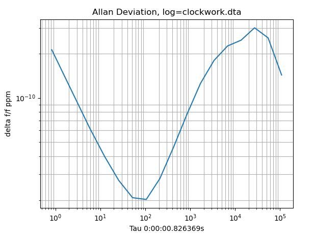
                        Re Allan, I'm measuring short term pendulum with timings with a 16MHz crystal, whilst the crystal is measured with a GPS pps reference. This mostly compensates for crystal instability, mostly due to temperature. Long term performance is measured relative to ordinary NTP, but I'm not using that with Allan.

                        The latest graph:

                        allanexample.jpg

                        The tau value looks OK, and is in the right range 10⁰ to 10⁵

                        Not sure about 'delta f/f ppm' because the range 10-¹⁰ is tiny. The curve might be right, but what does it mean.

                        What it's displaying is 'Pendulum Period Time, measured in ticks with a 16MHz crystal, that's been compensated relative to a GPS pps tick, where the tick has been converted and rounded to microseconds by diciding by the crystals average frequency'. Feel free to say if this is bonkers, I don't really understand what I'm doing!

                        Thanks

                        Dave

                        #627548
                        John Haine
                        Participant
                          @johnhaine32865

                          Michael, it's the standard method of deriving a high frequency clock in processor chips from a low frequency crystal, which is desirable for cheaper crystals and low oscillator power consumption.

                          #627585
                          Michael Gilligan
                          Participant
                            @michaelgilligan61133
                            Posted by John Haine on 04/01/2023 12:49:20:

                            Michael, it's the standard method of deriving a high frequency clock in processor chips from a low frequency crystal, which is desirable for cheaper crystals and low oscillator power consumption.

                            .

                            Thanks, John … I didn’t know that

                            That much admitted; it surprises me that [these days] anyone would go to the trouble.

                            Crystal oscillators of middling performance are cheap and plentiful.

                            MichaelG.

                            #627598
                            John Haine
                            Participant
                              @johnhaine32865

                              Well in your PC the processor is clocked at some GHz but needs to be stable. Given a few million gates in the processor a few extra in the PLL is neither here nor there.

                              #627602
                              Michael Gilligan
                              Participant
                                @michaelgilligan61133

                                You’ve said it twice, John … but I still don’t understand the relevance, when Dave’s starting-point was a simple, and inherently inaccurate, resistor/capacitor circuit.

                                As Boris once said … it’s like polishing a Turd.

                                Don’t worry about it, I’m tired and going to bed early

                                MichaelG.

                                #627704
                                SillyOldDuffer
                                Moderator
                                  @sillyoldduffer
                                  Posted by Michael Gilligan on 04/01/2023 21:34:12:

                                  You’ve said it twice, John … but I still don’t understand the relevance, when Dave’s starting-point was a simple, and inherently inaccurate, resistor/capacitor circuit.

                                  Wires crossed slightly I think. For speed, my Nucleo microcontroller is clocked at 180MHz. The clock synchronises the machine's internal operations, and provided they stay in step, all that's needed is a reasonably stable square wave. An accuracy of about 1% is adequate unless the microcontroller takes accurate time measurements.

                                  The easiest way to get a clock running at tens of megahertz is to multiply a low frequency oscillator up with an integer, usually in factors of 2 and 3. So 16MHz x 3 x 3 results in 144MHz, and 16 x 2 x 2 x 3 is 192MHz. This method can't get 180MHz from 16Hz!

                                  Another way getting a high-speed clock is by phase locking two oscillators. A free-running oscillator runs unstably at about 180MHz whilst the other runs much more stably at 16MHz. The trick is to connect the two together such that the high-frequency oscillator is synchronised with the low frequency oscillator, achieving high frequency and good stability together. Same principle as the Robinson Clock mentioned earlier, except he only got one synchronisation signal per day, which is hard to build on, rather than 16 million corrections per second. Phase lock loop electronics are a little complicated, but not significantly compared with the rest of the computer.

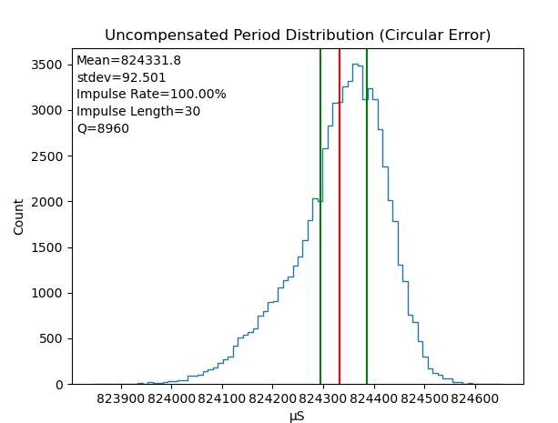
                                  Today's results are good despite me messing up fitting the cover yesterday by bashing the clock. After resetting I had to increase the impulse to get reliable running. May have overdone it, because the distribution is biased towards fast beats, rather than centred around the mean.

                                  q5jan.jpg

                                  Q is improved to 8960. Possibly this is because re-levelling the clock de-stressed the suspension, but no doubt the bob being draughtproofed helps too.

                                  Time keeping is OK: 0.32s slow after 16 hours uncompensated, 0.06s fast after compensation.

                                  Next job is to compensate in the clock. Looks good in theory, but making stuff work in practice isn't so easy.

                                  Dave

                                  #627742
                                  Michael Gilligan
                                  Participant
                                    @michaelgilligan61133

                                    Posted by SillyOldDuffer on 05/01/2023 16:26:19:

                                    […]

                                    Wires crossed slightly I think. […]

                                    .

                                    I will happily accept that, Dave …

                                    and will try to avoid attempting to discuss things that are out of my depth.

                                    Trouble is; to my feeble brain this all seems a bit too much like the ‘interpolation’ of digital images.

                                    [ No …I don’t want an explanation of why it isn’t … thank you ]

                                    MichaelG.

                                    #627976
                                    SillyOldDuffer
                                    Moderator
                                      @sillyoldduffer

                                      Yesterday I modified the clock to keep it's own time corrected for temperature and pressure. The result depends only on the pendulum and isn't influenced by GPS or any other external time reference. They're only used to measure performance.

                                      After only 19 hours, the clock is 75 seconds fast, a cruel disappointment.

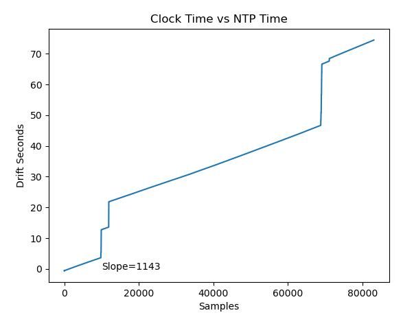
                                      Still hope because the graphs and data log show I still have software problems. Clock vs actual time (NTP) shows the biggest error is due to three step jumps:

                                      freeclockntp.jpg

                                      The log shows these jumps are always associated with corrupt data. This example shows beat number 69071 jumps 0.744 seconds and all the data values are correct apart from the tick count, which is 1271824 when it should be close to 13174874.

                                      69071 1271824 0.4136 0.3600 28 984.46 84.57 14.44 824435 1673076005 736565 1673075946 582831 –0.7443499999999972

                                      Seems that once in a blue moon (202 errors in 83107 beats), the clock hardware registers a beat correctly, but the tick count is mangled and the log output delayed. Been trouble with this before, and I thought I'd fixed it. Obviously not! However, I have a good idea what's wrong and shall test another fix today.

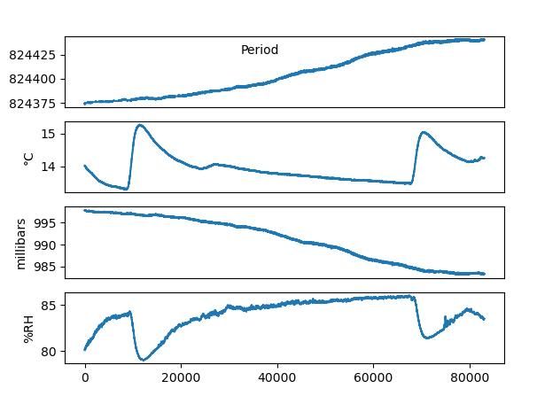
                                      Another problem is that barometric compensation isn't working properly, period rising as pressure falls:

                                      freeclocksummary.jpg

                                      I think I know the cause, but not what to do about it. Faulty application of the statistics is suspected. I understand how to compensate for temperature changes OR how to compensate for pressure, but am far from convinced I know how to do both. I've assumed they can be compensated together in the clock code, and although the barometric error is small, about 5 microseconds per millibar, any link being evident at all suggests I'm wrong. Needs more thought. Might have to start another thread on fixing my iffy mathematics!

                                      Dave

                                      #627985
                                      John Haine
                                      Participant
                                        @johnhaine32865

                                        Are you calculating the multivariate regression Dave?

                                        #628020
                                        SillyOldDuffer
                                        Moderator
                                          @sillyoldduffer
                                          Posted by John Haine on 07/01/2023 12:28:18:

                                          Are you calculating the multivariate regression Dave?

                                          No, because I don't understand how to program it! I'm using python numpy and could use scipy. both or which have simple functions for linear regression. Multivariate is a step too far for me because I couldn't find an example I understand.

                                          Instead, I regress temp versus period to get y=mc+x

                                          Then, having recalculated period by applying y=mx+c, to correct for temperature, I regress pressure against corrected period to get another y=mx+c

                                          Thus I hoped the second y=mx+c corrects for both temperature and pressure.

                                          Though it sort of works, I'm uneasy about my method, and the results confirm it's not working properly.

                                          Dave

                                          #628043
                                          Michael Gilligan
                                          Participant
                                            @michaelgilligan61133
                                            Posted by SillyOldDuffer on 07/01/2023 11:47:28:

                                            […]

                                            Another problem is that barometric compensation isn't working properly, period rising as pressure falls:

                                            .

                                            I hope you don’t mind me mentioning this, Dave … I think that statement is more exactly true than you might have thought when you wrote it. [at least in terms of your plots, if not in reality]

                                            I have just copied your picture and flipped it: and so far as I can tell visually, they match precisely.

                                            Unless I am stating the obvious [in which case, shut me up], I would suggest you check what data you are actually plotting.

                                            MichaelG.

                                            #628044
                                            duncan webster 1
                                            Participant
                                              @duncanwebster1

                                              Multivariant analysis is far too clever for me, but you could perhaps reduce the number of variables. Temperature, pressure and humidity all change the air density, which affects buoyancy, so you can calculate density, then you only have that and the temperature effect on length to worry about instead of 3

                                              Edited By duncan webster on 07/01/2023 17:21:34

                                              #628065
                                              John Haine
                                              Participant
                                                @johnhaine32865

                                                Dave, Excel will in fact compute multivariate regression coefficients, I'll try to remind myself of how to do it. You need the "data analysis" toolpack IIRC which is free to download. Alternatively (and much better once you have a lot of data) there's a free but incredibly powerful package called R Studio which is used by all kinds of professional statisticians which will eat this kind of problem for breakfast. Inevitably a bit harder to use but once you get the up the learning curve fairly easy to apply.

                                                Also reading back over the pendulum-nuts mailing list I came across some postings about barometric pressure measurements which made the point that you probably need to do some smoothing on the raw pressure measurements since there can be very rapid fluctuations at short time scales. These might affect the statistical analysis but not actually the pendulum so much.

                                                #628092
                                                David Tocher
                                                Participant
                                                  @davidtocher94033

                                                  Multivariate linear regression isn't that difficult. As others have said there are lots of tools out there. Excel with add-ins is fine.

                                                  You are assuming a linear relationships between the dependent variable (y) and the x_i independent variables. Given the independant variable changes are small is a reasonable assumption.

                                                  One thing multivariate analysis will give is the covariance matrix which indicate how the independent variables are correlated. I suspect temperature and pressure are but it might be seasonal. High pressure in the winter is usually associated with cold weather and the reverse in the summer (for Atlantic Europe)

                                                  #628143
                                                  John Haine
                                                  Participant
                                                    @johnhaine32865

                                                    There's a good explanation of how to do multivariate analysis in Excel here:

                                                    https://smallbusiness.chron.com/make-regression-table-excel-30870.html

                                                    There's also an Open Office calc extension doing something similar.

                                                    #628159
                                                    SillyOldDuffer
                                                    Moderator
                                                      @sillyoldduffer
                                                      Posted by David Tocher on 07/01/2023 23:36:07:

                                                      Multivariate linear regression isn't that difficult. As others have said there are lots of tools out there. …

                                                      That's easy for you to say, but I'm way out of my depth! My fault I know, but my sadly limited mathematical abilities are stretched on this one and it's new territory for me. A-level science, but further progression abandoned due to weak maths.

                                                      After some light reading I now understand multi-variate and multivariable regression are often confused by beginners, but not which of the two is appropriate to my case. I think my requirement is multivariable and the answer should be a scalar. Unfortunately the implementation examples I've found are multi-variate, where the answer is a vector. I want to do something fairly simple, instead I'm trying to understand material using words like homoscedasticity.

                                                      I feel like that passenger in an air disaster drama who has to land a jumbo jet based on 10 minutes experience watching someone else playing Microsoft Flight Simulator 20 years ago!

                                                      I know there are lots of tools, the problem is I don't understand how to use any of them. I'd rather stick with Python if I can. It's strong on statistics and scientific number crunching because it has modules written for this type of job. Nothing wrong with R, except the learning curve – I don't know R at all. Excel, or any other spreadsheet, is likely to be unsuitable because of the size of the dataset. A minimum 3 columns of at least 100,000 rows, and the biggest I've created so far was over 1.5 million rows.

                                                      Single linear regression in Python with the numpy or scipy modules is easy. Given a list of periods and corresponding list* of temperatures then, with numpy polyfit():

                                                      tmodel = np.polyfit(temps,periods, 1)

                                                      tmodel is a tuple containing the x and c values needed to solve y=mx + c, from my data:

                                                      Temperature-model=
                                                      12.56 x + 8.242e+05
                                                      [1.25622792e+01 8.24239035e+05]

                                                      I was hoping to find a function like 'np.polyfitn(temps,periods,pressures,1) that did much the same job with three lists.

                                                      Unless I'm missing something, the code needed is considerably more complicated, like this example, which needs a lot of thought. I understand the program's syntax but not its logic.

                                                      I am the boy at the back of the class who took 3 years to get percentages…

                                                      sad

                                                      Dave

                                                    Viewing 25 posts - 276 through 300 (of 562 total)
                                                    • Please log in to reply to this topic. Registering is free and easy using the links on the menu at the top of this page.

                                                    Advert

                                                    Latest Replies

                                                    Viewing 25 topics - 1 through 25 (of 25 total)
                                                    Viewing 25 topics - 1 through 25 (of 25 total)

                                                    View full reply list.

                                                    Advert

                                                    Newsletter Sign-up