Experimental Pendulum Clock

Advert

Experimental Pendulum Clock

Home Forums Clocks and Scientific Instruments Experimental Pendulum Clock

Viewing 25 posts - 251 through 275 (of 562 total)
  • Author
    Posts
  • #626199
    Michael Gilligan
    Participant
      @michaelgilligan61133
      Posted by SillyOldDuffer on 26/12/2022 14:41:47:

      […]

      On a positive note, a potential source of measurement error is eliminated. The GPS enhancement confirms the clock's temperature drift is mainly due to the pendulum, not the Arduino crystal.

      Dave


      .

      That’s actually great progress, Dave … You have a real quarry to hunt-down now yes

      MichaelG.

      .

      .

      As an entirely non-confrontational footnote:

      From Wikipedia, the free encyclopedia

      Tilting at windmills is an English idiom which means "attacking imaginary enemies", originating from Miguel de Cervantes' novel Don Quixote.

      Edited By Michael Gilligan on 26/12/2022 15:15:17

      Advert
      #626606
      SillyOldDuffer
      Moderator
        @sillyoldduffer

        Before xmas, thanks to John Haine, I ordered a second-hand 10MHz Oven Controlled Crystal Oscillator. Not the best OCXO ever made, but only cost a few pounds and it's 5 times better than anything else I have. The output is a 5V logic level too, ideal. It needs to be boxed up and powered.

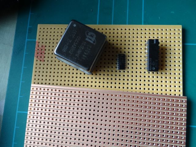
        Annoyingly, the microcontroller the OXCO is intended to feed has a maximum external clock speed of 6.4MHz, so simply stuffing 10MHz into it won't work. Not a big problem I thought because there are lots of chips which will divide by two, and the microcontroller will be happy with a 5MHz input. Silly me. My junk box failed to provide a suitable chip, so I ordered a couple, which arrived yesterday. Big mistake, they're sub-miniature, which don't go well with my eyesight and clumsy soldering technique. What I assumed was an old-school 14 pin dual in-line package, a type that's become rare with passage of years.

        Wanting to show the difference, and to show that the older DIP package fits neatly into a 0.1" stripboard, I grabbed an example at random and took this photo:

        dsc06654.jpg

        As can be seen, the pins on the tiny chip don't line up with the copper strips or the hole grid. This is a right pain, because I either have to source a larger chip, or make a printed circuit board, or make a carrier for the small chip. A simple job suddenly got complicated.

        However, at this point I noticed the workshop gremlins had got me good and proper. The random chip in the photo in a 7490, a decade counter equivalent to the tiny one, and exactly what was needed in the first place. So I've wasted time and money!

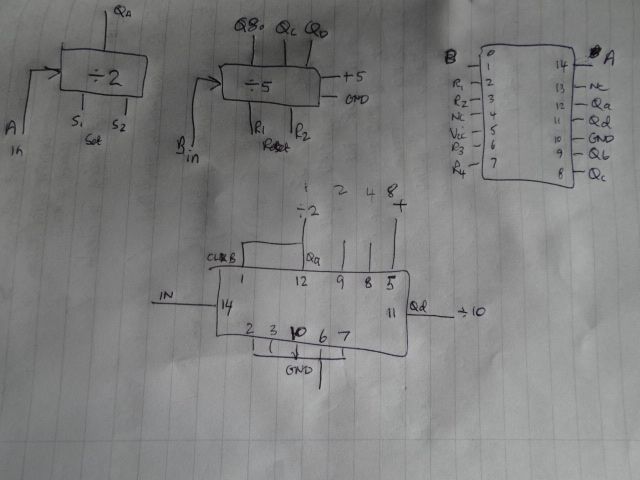
        Moving on, I have to assemble this circuit:

        dsc06655.jpg

        10MHz from the OXCO will be taken direct to one BNC socket, whilst pin 12 on the chip puts 5MHz on a second. I'll also use the chip's divide by 5 module to put a 1MHz output on a third socket.

        A problem solved though is that the OXCO pins aren't on a standard 0.1" setting. However, it will fit standard stripboard if rotated as shown, and a hole is enlarged for the slightly off earth pin.

        Dave

        #626659
        Michael Gilligan
        Participant
          @michaelgilligan61133

          Dave,

          If you really want to get into this … may I recommend: **LINK**

          http://jrmiller.online/projects/freqstd/frqstd.htm

          Please don’t ask about mine though … it’s a long and very sorry tale, and it won’t do me any good to recite it here.

          sad MichaelG.

          #626662
          John Haine
          Participant
            @johnhaine32865

            I'm planning to have a go at this one:

            https://www.eevblog.com/forum/projects/lars-diy-gpsdo-with-arduino-and-1ns-resolution-tic/

            Not sure where it is in the project queue though…

            #626684
            duncan webster 1
            Participant
              @duncanwebster1

              This has gone way above my understanding, but I do have some Arduino mini boards (not pro mini) which have a stonking big crystal rather than a resonator. Would these be any use?

              #626895
              SillyOldDuffer
              Moderator
                @sillyoldduffer
                Posted by duncan webster on 30/12/2022 00:56:20:

                This has gone way above my understanding, but I do have some Arduino mini boards (not pro mini) which have a stonking big crystal rather than a resonator. Would these be any use?

                Kind offer thanks Duncan, but I'm already using Arduinos with crystals rather than resonators. The latest iteration is running on a Mega 2560, mainly because it has two hardware timers I can use for input capture rather than one. The first timer counts crystal ticks per pendulum swing, the second counts crystal ticks per GPS second.

                Not all the Arduino processors are suitable; it's a combination of clock features, number of counter/timers, counter capability, and whether or not the necessary pins are made available. The Nano Every is very promising, but turns out it's timers don't support what I'm doing.

                I'm looking again at the Nucluo, which has a fast 32 bit processor, but a complicated clock system, and a programming manual I don't understand. Also investigating the possibility of building a GPSDO based on Michael and John's input.

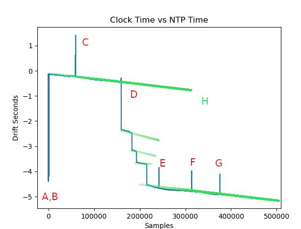
                Meanwhile the latest clock graph has started an investigation:

                glitches.jpg

                I don't know what caused the A & B down spikes, or the C,E,F, G up spikes. Or the down staircase at D. Maybe a bug in the maths, because the log data doesn't seem to be jumping about. But as the changes are quite small, I'm writing a program to zoom in on anomalies.

                The green slopes, showing GPS and NTP are apparently drifting apart, might well be due to rounding error. I measure the pendulum in 16MHz crystal ticks giving 8 digit precision, but my clock code truncates them into 6 digit unrounded microseconds. Better I think to alter the clock to measure internally in crystal ticks rather than microseconds, only converting to human time after the sums have been done .

                Good news though is that a simulation of the temperature compensation code looks effective, so I need to implement it in the clock, and then add barometric compensation as well. I'm optimistic this might work reasonably well and there are more improvements in the pipeline.

                If I was running this as a project, I'd sack the Designer, Machinist, Programmer and Mathematician because they've all made silly mistakes. Unfortunately these roles are all done by me and I have to put up with the team I've got.

                Dave

                Edited By SillyOldDuffer on 31/12/2022 14:02:08

                #627128
                SillyOldDuffer
                Moderator
                  @sillyoldduffer

                  Pleased to report I found and fixed a bug in the clock code that corrupted the output log randomly. Nine times in nearly a million samples! The total error was less than 7 seconds, but that's serious in a device aiming for accuracy better than 1 part per million.

                  The latest run, 27 hours so far, is looking good. Interestingly, correcting for temperature left an error of 41 seconds, which is dreadful. However, correcting for air pressure in addition reduced the error to 0.033s – much more respectable, but highlighting my pendulum is sensitive to both temperature and pressure change.

                  A rise in either increases the period. Which one has most effect depends on the weather. I guess sensitivity to air pressure is due to the light weight of the bob, presumably it being more effected by buoyancy and viscosity than a bigger one?. Might order some tungsten putty!

                  Dave

                  #627146
                  John Haine
                  Participant
                    @johnhaine32865

                    It's the density rather than mass which is important. Baro sensitivity is reduced in proportion to the ratio of air density to Bob density.

                    #627151
                    SillyOldDuffer
                    Moderator
                      @sillyoldduffer
                      Posted by John Haine on 02/01/2023 08:01:33:

                      It's the density rather than mass which is important. Baro sensitivity is reduced in proportion to the ratio of air density to Bob density.

                      Point taken, thanks.

                      Now I'm in another dither! Tungsten putty weighs about 10g per cc, compared with steel at about 7.5g per cc. But, a solid steel bob is easy to make and physically stable, apart from rusting, and it has suitable magnetic properties. Tungsten putty would have to sit in a steel can, and – being a putty – it's stability is uncertain. And is the bob worth fixing in a clock that can compensate for air pressure, that I hope to run in a vacuum? In principle, I think the pendulum should be as mechanically good as I can make it, but this diverts from my original plan which as to keep the mechanicals super-simple.

                      Did some swotting on the ideal bob shape last night. Seems somewhat uncertain! Jury out on the lenticular type, which I would have guessed to be optimum, the problem being a lens shape exposes a lot of surface to air resistance. Seems agreed a cylinder, like mine, is the worst shape due to turbulence, and a sphere might be best.

                      Feels wrong that a steel bob swinging rather slowly in air should suffer from buoyancy and viscosity effects, but it does!

                      This morning is devoted to debugging and improving the clock software:

                      • Two bugs that don't effect operation, but I don't understand the cause. They might be symptoms of something more serious.
                      • Applying temperature and barometric compensation inside the clock. At the moment the compensation maths is tested post mortem on the log file, and compensation code needs to be written and proved in the real world.

                      I'm waiting for one last part to arrive before boxing up the OCXO. It's a USB socket needed to provide power. Sod's Law ensures the connector determines the component layout inside the box. It can go anywhere, but has to be measured so the rest fits around it. Nothing is ever easy…

                      Dave

                      Dave

                      #627152
                      Michael Gilligan
                      Participant
                        @michaelgilligan61133

                        Dave

                        I am sending you an ebay link which might be of interest

                        The seller is in Bristol, so you could probably nip round to check

                        MichaelG.

                        #627155
                        John Haine
                        Participant
                          @johnhaine32865

                          Dave, have you seen Doug Bateman's article on bob shapes? He measured the Q of a range of shapes and carefully documented the results. I'm sure I could track down a copy.

                          #627158
                          duncan webster 1
                          Participant
                            @duncanwebster1

                            I've seen an article somewhere that claimed that bobs should be shaped like a rugby ball. I think your best bet for high density is the copper tungsten alloy, but to make it work in your configuration you'd need to incorporate some iron.

                            #627164
                            SillyOldDuffer
                            Moderator
                              @sillyoldduffer
                              Posted by John Haine on 02/01/2023 10:15:51:

                              Dave, have you seen Doug Bateman's article on bob shapes? He measured the Q of a range of shapes and carefully documented the results. I'm sure I could track down a copy.

                              No, not seen and would be grateful to eyeball a copy. I was reading Woodward's "My Own Right Time", who summarises Bateman over a page or so.

                              Ta,

                              Dave

                              #627171
                              Joseph Noci 1
                              Participant
                                @josephnoci1
                                Posted by John Haine on 29/12/2022 20:53:04:

                                I'm planning to have a go at this one:

                                https://www.eevblog.com/forum/projects/lars-diy-gpsdo-with-arduino-and-1ns-resolution-tic/

                                Not sure where it is in the project queue though…

                                Unless you have a 'good' quality OCXO, don't spend to much time on the 'time-to-digital' type of PPS jitter measurement circuits.

                                The Lars cct types, using an RC charge network and reading with an A/D in the processor needs careful design and layout to ensure cct noise does not influence the reading. For an average OCXO, it is a lot simpler to use a frequency lock type loop – 1PPS starts an overflow timer ( clocked with CPU clock..) and the timed residual is read at the next 1PPS – the residual relates directly to the 1PPS jitter and this is filtered in a slow IIR filter in the cpu. Use that to generate a PWM output, integrated to DC to drive the OXCO voltage control input. – maybe 5 or 6 chips plus a GPS…Before getting anxious re the CPU clock drift, tempco, etc – that add a very useful external shift to the counter operating point, and helps overcome the hanging-bridge control point on the OCXO…

                                The original GPSDO fellow was Brooks Shera – here is his original concept, using external counters – newer micros allow all that internally.

                                Brooks Shera GPSDO

                                This fellow has very good info and a useful design:

                                VE2ZAZ GPSDO site

                                and

                                **LINK**


                                GPS devices such as the UBLOX 7 and 8 series , with TCXO, can be programed via the serial interface and the UBLOX free SW tool to setup the 1PPS output to output almost any frequency. The base frequency in these units is 48MHz, so any output that is not an integer divisor will have jitter on the waveform. 8MHz seem to be 'jitter free', but is a nasty frequency – needs feeding into an Si5351 PLL set to give 10MHz, etc…still with some jitter. However, feeding an external PLL (4046 type) with a long time constant can result in a very clean low jitter signal, so that is another way to get frequency much more stable than you arduino table top clock, but not 'true GPSDo' quality…I am sure it will suffice for the pendulum measurements!


                                This is a good read, and shows the hanging bridge issue – pg 23

                                **LINK**

                                I have built a few GPSDO's – one with an old HP OCXO of very good performance (from a Tube Defunct Ceasium Beam standard), and one with a very good but not as good as the HP OCXO, new, from Golledge in the UK.

                                I have used the Freq-Lock loop method, the RC '1ns' resolution A/D method and a Texas TID chip, with 100ps resolution – some very good Allen dev results…

                                BUT, Beware!! if you start down this road, the next is a stop at Time-Nuts and then its tickets….You will chase that elusive extra 10 minus 1 down a long road to lost time…

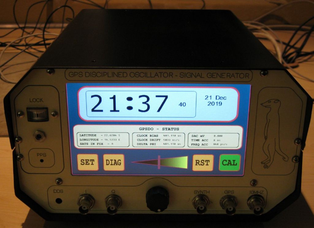
                                front main page.jpg


                                Edited By Joseph Noci 1 on 02/01/2023 11:31:02

                                #627196
                                duncan webster 1
                                Participant
                                  @duncanwebster1

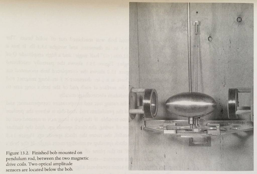
                                  This is an abstract from a book on pendulums by James Matthys in which he mentions the best shaped being a prolate spheroid, which is academic speak for rugby ball (or football if you're American). He says that a cylinder with 120 degree pointed ends is pretty good, but no mention in the abstract of L/D ratio. The long axis is in the direction of travel obviously. However unless the rod is non circular it won't be easy to make sure that the long axis is aligned, hence the use of spherical bobs, which are a non oblate spheroids

                                  no-one has mentioned the drag on the pendulum rod. This suggests it is not necessarily negligible. Perhaps SOD is on to something with his thin carbon fibre rod

                                  #627203
                                  Michael Gilligan
                                  Participant
                                    @michaelgilligan61133
                                    Posted by duncan webster on 02/01/2023 12:50:19:

                                    This is an abstract from a book on pendulums by James Matthys in which he mentions the best shaped being a prolate spheroid, which is academic speak for rugby ball (or football if you're American). […]

                                    .

                                    My copy of Matthys is packed-away at the moment; but I don’t recall him exploring the proportions of that shape in any great detail. … I may be wrong, and perhaps John Haine could advise.

                                    Obviously there is a geometric similarity between all prolate spheroids, but I suspect the devil would be in the detail.

                                    MichaelG.

                                    .

                                    Ref. for geometry __ **LINK**

                                    https://mathworld.wolfram.com/ProlateSpheroid.html

                                    #627204
                                    Martin Kyte
                                    Participant
                                      @martinkyte99762

                                      Just to complicate thing’s further, I seem to remember some data in MORT (I think) relating to door open and door closed results. Most precision pendulum’s are housed in a reasonably large enclosure whereas S O D,s is in a fairly small diameter tube. The displaced air has to go from the front to the back in an oscillating cycle so there is work done and consequently energy absorbed in achieving this. Fortunately the tube walls will be smooth so skin effects will be less than say wood but there is the viscosity losses too.
                                      regards Martin

                                      #627206
                                      Michael Gilligan
                                      Participant
                                        @michaelgilligan61133
                                        Posted by duncan webster on 02/01/2023 12:50:19:

                                        […]

                                        no-one has mentioned the drag on the pendulum rod. This suggests it is not necessarily negligible. Perhaps SOD is on to something with his thin carbon fibre rod

                                        .

                                        Interesting reference that ^^^ thanks Duncan yes

                                        I was more than a little surprised, though, to see them using Nylon monofilament as the ‘string’

                                        s-t-r-e-t-c-h-y stuff, is it not ?

                                        MichaelG.

                                        #627218
                                        John Haine
                                        Participant
                                          @johnhaine32865

                                          Dave, actually I'm not sure that it has been published as an article – I know Doug and will ask him for the reference. There's a more complete summary in the "new Rawlings".

                                          I did some limited experiments on rod diameter for my new clock, going from 10mm down to 3mm diameter. Smaller is definitely better but not by a huge factor, there are reasons for using a slightly larger diameter, I'm using 6mm OD so I can mount a little bar magnet in it.

                                          Thanks for the info Joe – too late, I've already caught the Time-Nute bus (again!).

                                          #627227
                                          SillyOldDuffer
                                          Moderator
                                            @sillyoldduffer

                                            Really helpful post Joe, thanks! I read the Brook's Shera article a few days ago thanks to John, thought it didn't look too difficult, especially as he had to deal with the extra jitter put on GPS signals by the US DoD. This has since been removed, and GPS receivers are cheaper too! A GPSDO has been added to my ever growing 'To Do' list.

                                            The work this project is generating seems endless. I realised this afternoon I need to write a program to simulate a pendulum losing and gaining amplitude. More work, just to test a simple change!

                                            Just a thought, but I know you favour Nucleo boards, and might be able to help with a coding issue. I'd like to program a timer in Input Capture mode with an external clock feed on a Nucleo F446RE, but I'm making heavy weather of the manual. Mbed doesn't seem to support Input Capture 'off the shelf'. STM Cube does, but I don't want to learn another environment just to get a few lines of time setup code. Have you any Nucleo timer examples?

                                            I'm struggling to understand my Allan graph too, but that's on the back-burner!

                                            Cheers,

                                            Dave

                                            #627373
                                            Michael Gilligan
                                            Participant
                                              @michaelgilligan61133

                                              I hope this brief quotation from “Accurate Clock Pendulums” is acceptable to the publisher:

                                              .

                                              7e26b367-e8fb-476f-9572-02abc3c2a20c.jpeg

                                              .

                                              ISBN 0 – 19 – 852971 – 6

                                              .

                                              MichaelG.

                                              .

                                              P.S. __ at the end of that very short [3 pages] Chapter, Matthys gives a reference to:

                                              D. Bateman. “Is your bob in better shape?” Clocks (June 1988), 34–7.

                                              Edited By Michael Gilligan on 03/01/2023 14:24:03

                                              #627386
                                              John Haine
                                              Participant
                                                @johnhaine32865

                                                I checked with Doug and the detailed results were only published in Rawlings 3rd edition.

                                                #627401
                                                SillyOldDuffer
                                                Moderator
                                                  @sillyoldduffer
                                                  Posted by John Haine on 03/01/2023 15:30:55:

                                                  I checked with Doug and the detailed results were only published in Rawlings 3rd edition.

                                                  Well that's bizarre! I have Rawlings 3rd Edn and was convinced the book only summarised bob shape. Not so, there's 9 pages! I think I've confused my sources. Please tell Mr Bateman he has a new fan!

                                                  Meanwhile I've cracked how to count ticks with a Nucleo F466RE hardware timer, hurrah. Looks promising. The computer clock runs at about 180MHz, giving a potential resolution of about 5.5nS per second, about ten times better than an Arduino. Next job is to check how stable the base oscillator is, and it may be poor.

                                                  Also, in hope of understanding what my Allan Variance graph means, I've been reading the NIST Handbook of Stability Analysis. Now my brain really hurts!

                                                  Thanks,

                                                  Dave

                                                  #627416
                                                  John Haine
                                                  Participant
                                                    @johnhaine32865

                                                    There's both Rawlings original and Doug's work in a separate section, I found it confusing too!

                                                    #627440
                                                    SillyOldDuffer
                                                    Moderator
                                                      @sillyoldduffer

                                                      I tested the clock stability of a Nucleo F466RE, and wasn't surprised to find it poor. After 4 hours Q 2788, and stability 2869ppm.

                                                      Problem is the chip gets a 180MHz clock by multiplying up from an internal 16MHz Resistor-Capacitor oscillator, accuracy about 1%, yuk. Although multiplication is done with a Phase Locked Loop, it's based on a wobbly oscillator. The board allows a crystal to be fitted.

                                                      Apart from that the Nucleo woks well, and I may be able to clock the timer from an external pin.

                                                      Dave

                                                    Viewing 25 posts - 251 through 275 (of 562 total)
                                                    • Please log in to reply to this topic. Registering is free and easy using the links on the menu at the top of this page.

                                                    Advert

                                                    Latest Replies

                                                    Viewing 25 topics - 1 through 25 (of 25 total)
                                                    Viewing 25 topics - 1 through 25 (of 25 total)

                                                    View full reply list.

                                                    Advert

                                                    Newsletter Sign-up