Enquiry into functionality of NVR (No voltage release) switches for 3 phase and single phase machine tools

Advert

Enquiry into functionality of NVR (No voltage release) switches for 3 phase and single phase machine tools

Home Forums Manual machine tools Enquiry into functionality of NVR (No voltage release) switches for 3 phase and single phase machine tools

Viewing 25 posts - 1 through 25 (of 29 total)
  • Author
    Posts
  • #117174
    SteveI
    Participant
      @stevei

      Hi,

      I have some questions about the functionality that NVR (no voltage release) switches (and associated components if any) perform, in respect to single and 3 phase machine tools. If this has been covered before please educate me on the specific thread. A search has not revealed the answers that I am looking for.

      I am renovating 3 old machine tools (2 3 phase and 1 single phase) that do not currently have NVR on off switches. I intend to fit the correct NVR solution to each machine. Since I started looking into sourcing the NVR switches I see quite a price range depending on the functionality.

      For the simple case for a single phase machine a NVR will as a minimum monitor and cut the live should the voltage drop below a threshold. Is it normal that they will also cut the neutral?

      For the 3 phase case do they cut all 3 phases plus the neutral? Do they monitor all 3 phases? I.e. are 1 or 3 phase NVR in effect AC voltage protection relays? I.e. they continuously monitor single phase or three phase AC voltages, tripping upon fault condition. A fault being outside nominal voltage. Do they also trip on phase loss, phase reversal, voltage unbalance?

      For reference note that I am currently based in Norway and I have 3 phase 220VAC into the home. (Norway has it's own electrical standard. "Single phases" is actually 2 live phase at 115VAC 120deg out of phase to produce 230VAC across the live and hot "neutral" plus an earth. The use of this uncommon "single phase" electric standard is the reaons I am looking for a NVR switch that cuts both poles for any single phase equipment. In my workshop I have a transformer that upconverts my 220VAC 3 phase to 400 VAC 3 phase and also provides a (near earth) neutral.

      Thanks,

      Steve


      Edited By SteveI on 17/04/2013 19:58:56

      Advert
      #12119
      SteveI
      Participant
        @stevei
        #117190
        Les Jones 1
        Participant
          @lesjones1

          Hi Steve,
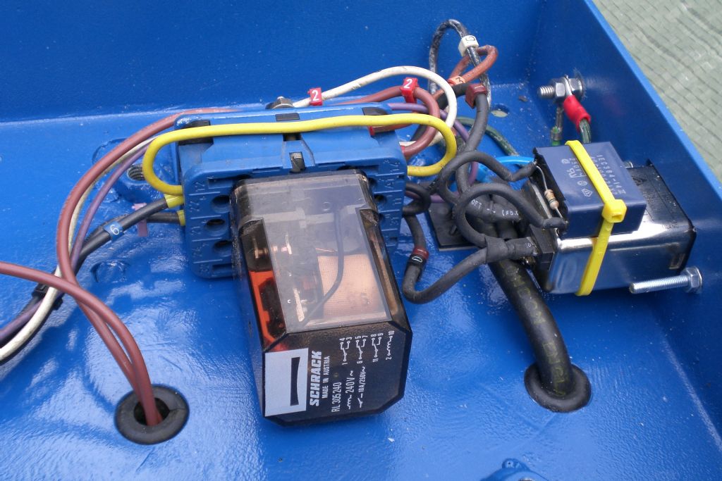
          An NVR is basically a relay with one set of contacts holding the coil energised. The start button just bypasses these contacts when pressed. After the start button is released the contacts on the relay keep the coil energised. The stop button is a normally closed contact that breaks the current to the coil when pressed. The very cheap NVRs do not have a separate stop and start button. On these the start button just pushes the relay closed and the stop button forces the armature away from the coil. The better NVRs also have thermal overloads which trip the NVR off if the current exceeds a set value for a period of time. They are normally called motor starters when they have thermal overloads. The number of sets of contacts on the relay (Normally called a contactor in this type of application.) determines if neutral and live are broken or just live.
          On three phase NVRs the coil is normally just between two phases so you could loose one phase and the contactor would not drop out. Another contactor could be added to prevent this but I have not seen this done. Another variation is to have a transformer so that the wiring to the start and stop buttons and safety interlocks is at a low voltage. The contactor then has a low voltage coil.

          Les.

          #117202
          Robbo
          Participant
            @robbo

            Steve,

            The modern NVR switch as fitted to most single-phase machines when new is usually a 2-pole switch, switching both line and neutral, which works as Les has described, ie opens the switch if the current fails.

            For 3-phase we usually use a contactor, also known as a DOL (direct on line) Starter. These have 3 coils and all three will be thrown out if current is interrupted. They also have an overload protection facility which varies of course depending on the rating of the machine. These 3-phase contactors are commonly used on single-phase applications by wiring two of the coils in series.

            Hope this helps, but if Ted Fletcher sees this thread I am sure he can enlarge on it.

            Phil

            #117260
            Peter G. Shaw
            Participant
              @peterg-shaw75338

              Hi Steve,

              Some years ago the "switch" on my lathe failed. At that time I did not know how they worked, and when I saw the cost of replacement systems, I decided to have a go at repairing mine. Which in turn required me to learn how they worked.

              Obviously I cannot be certain that all "switches" work like mine, but have no reason to believe that they are not similar. Anyway, here goes:

              The same device can be used for both 3-phase and single phase supplies by means of internal re-arrangement of the wiring. There is only one relay/contactor in the device and its coil is connected between either the Live & neutral for single phase working, or any one of the three phases and neutral for 3-phase working. I suppose it is assumed that if one phase of a 3-phase system fails then all phases will have failed.

              The relay/contactor has 4 contacts – one is used to provide a hold path for the relay/contactor and is usually wired via all the safety cutouts on the machine. The other three contacts are used to disconnect the three phases in a 3-phase system, or are wired effectively in series for a single phase system.

              Also, there may be an overload device – in my case this is nothing more than three bimetallic strips surrounded by small heating coils. Each coil is connected in series with one of the phases in a 3-phase system and hence in series with each of the three motor coils, whilst in the single-phase system, they are all effectively in series along with the supply to the motor. Therefore each coil is heated by the motor current and if one coil takes too much current, the bimetalic strip bends and breaks the relay/contactor holding circuit and thus disconnects the power.

              In your case, you will need to determine whether or not the relay/contactor will operate and hold to one half of the power supply. If so, then you should be able to wire the relay/contactor for 2-phase working. Otherwise wire it as for single phase using the full power supply. In respect of the overload coils, these will have to be wired as for single phase, ie all three coils in series.

              If you have a look at MEW192, you will see some diagrams for my lathe which may help you to understand how my system works, and how I was then able to replace my faulty relay/contactor with 4 contacts (for 3-phase working) by a relay with only 3 contacts (for single-phase working).

              Regards,

              Peter G. Shaw

              #117377
              john fletcher 1
              Participant
                @johnfletcher1

                Hello Steve, I think this might answer your questions, should you have any other question feel free to contact me.

                Here in UK we don’t under normal circumstance ever switch the Neutral, all our lighting circuits are switched lives. All Three phase motor circuits are three phases only, neutral not needed.

                Both Poles in single phase motor system are switched, but I’m not sure of your electrical system in Norway, possibly you switch both HOT wires. Maybe a North American/Canada reader might enlighten us all on how they go on. I know they have 120 and 220 for heavier loads.

                Les, Phil and Peter are quite right in what they say.

                Answering your question in Para. 3. Yes, here in UK we switch both live and neutral in single phase motor circuits. I think you would do the same in Norway on your 220 volt two hot wire system, but not sure.Ted

                Para. 4. You don’t need a neutral in a 400 volt three phases motor system. Regarding no volt release, over load protection, these are part and parcel of the normal motor starters, found in run of the mill applications

                single phasing, such as home workshops. The other facilities such as single phasing monitoring are only found on the expensive industrial drives

                You didn’t say the size of your machine motors, be generous with the cable size. Motors can cause a large voltage drop when starting up together with a large initial current surge, up to 8 times normal running current.

                I suggest you consider reconnect the motors in Delta, so that they will run on 220 volt three phase, usually it’s only a matter of moving links around in the terminal box, from the horizontal to vertical positions, not a big job.

                For an explanation, draw yourself three coils in a Y, shape. Call one coil V the next U and the third W, each coil must have a start and finish on its windings. The centre part of the Y is where all the start ends are connected ( normally known as the one ends and star point) obviously now the outer must be the two ends, this is where we connect the 400 volt three phase from the electric mains, via switch gear and starter, this now known as STAR connected motor.

                So you have V1 & V2, U1&U2, and W1&W2.

                Now draw a delta shape, label the coils V, U, and W , start at the bottom left hand side V1, the obviously its top must be V2 which connect to W1, the other end of

                W1 is W2 which connects to U1, finally U2 connects to V1.The motor is now 220 volt three phase, connect the 220 volt three phases from the mains supply to the outer points. If you connect your motors as I described above you could control them via inverters then you would have speed control as well.

                #117386
                Sub Mandrel
                Participant
                  @submandrel

                  I case anyone with appropraie experience decides to wire up their own NVR, when I did this I found that I had to use a bridge rectifier to power the relays, otherwise they were unreliable, despite the coils being AC rated. No smoothing was required.

                  Neil

                  #117400
                  Mike Poole
                  Participant
                    @mikepoole82104

                    The purpose of the NVR is to prevent the automatic restart of equipment in the event of a supply failure. It is desireable to use an NVR on a machine tool as in the event of power failure the machine will stop, if we rely on the operator to turn off the machine he may not realise what has happened and not turn it off, when power is restored he may not be in attendance when the machine restarts and if any auto feeds were engaged major damage to the work or machine could occur, injury could occur if the operator or third party were working on the machine when auto restart happens. Auto restart is often required on devices like pumps where no equipment or operator damage will occur.

                    On a large piece of eqipment the NVR will kill the whole control circuit. On a device like a motor starter the contactor will serve the purpose of NVR and motor starter, the motor overload unit will often be wired into this contactor. The other conditions like low voltage and phase failure are not the function of an NVR.

                    Mike

                    #117634
                    SteveI
                    Participant
                      @stevei

                      All,

                      Thanks very much for all the kind and educational advice. I have also spoken to some of the suppliers that have been linked in previous postings of a similiar topic. Some of whom didn't know what there projects functionality was.

                      Based on this I speculate that what I originally assumed would be the 3 phase functionality is not common. What I thought would be normal is something such as the Schneider elektro Phase Failure Relay Class 8430 Type MPD (http://static.schneider-electric.us/docs/Machine%20Control/Relays%20and%20Timers/Relays-Control%20and%20Measurement/8430MP%20Phase%20Failure%20Relays/65013-008-89.pdf) or the Eltime controlls (http://www.eltime.co.uk/product.php/28/Phase%20Protection%20Relays.html) phase protection relays.

                      It would seem to me that in my set-up I might consider one of those on the input side to my 230VAC to 400VAC transformer. And then rely on more normal NVR switches on the machine tools. Having said that for a home workshop it might be a bit OTT.

                      Regarding the suggestion re-wire to delta I'll take it under advisement. My lathe is ~2HP/ 1.5 KW, and the other tools much less. (Still on the lookout for a mill). I plan to use some 2.5mm2 wire for each of the 3 phases and also the earth.

                      Many thanks,

                      Steve

                      #117684
                      Peter G. Shaw
                      Participant
                        @peterg-shaw75338

                        Stub/Neil

                        Normally I would agree that for a relay to operate reliably on ac it will need a rectifier of some description and possibly with a capacitor for smoothing, however, the relay I used was specified as being designed for 240Vac use (RS Components 348-813). There is no rectifier or capacitor and it works fine with no buzzing.

                        Regards,

                        peter G. Shaw

                        #117694
                        Anonymous

                          As a generalisation DC relays don't care which way round the DC is applied to the coil. They work equally well either way round. So in an AC relay the contacts close on each cycle irrespective of the applied voltage. However, an AC relay will tend to open as the applied voltage goes through zero. So AC relays have a shading pole that tends to retain some residual magnetism in the core as the voltage goes through zero, thus keeping the contacts closed until the applied voltage rises again. That's why AC contactors 'chatter' if the pole pieces are dirty and don't quite mate, thus reducing the maximum magnetism. The residual magnetism isn't then quite enough to keep the pole pieces closed, so they start to open, before being closed again as the voltage rises.

                          Regards,

                          Andrew

                          #117700
                          MICHAEL WILLIAMS
                          Participant
                            @michaelwilliams41215

                            Does anyone make an all electronic NVR ??

                            #117707
                            john fletcher 1
                            Participant
                              @johnfletcher1

                              I am not familiar with the current wiring regulations, but pretty certain that an electronic NVR wouldn't comply, as there has to be a definite physical air gap between contacts. Which is not possible with semi conductor devices. Its possible to operate AC relays on DC using the appropriate value series resistor, not without ! Just buy a proper starter, thats the way to go, then you have contacts of the right size and all that goes with it. Relay contact are tiny compared to those on a motor starter and motors take a large intial surge current when starting up to 8 times full load current.Ted

                              #117724
                              Peter G. Shaw
                              Participant
                                @peterg-shaw75338

                                It all depends on how you use them. For any switching contact, the most onerous condition is when breaking an active circuit, followed by making an active circuit. In both instances contact bounce will cause arcing and burning of the contacts. However, if the contacts are operated well before current is drawn, then contact bounce should be nil hence the steady state current rating of the contacts can be used and this is usually much higher than the switching rating. Of course, there is still the possibility of local heating on the contacts.

                                In my case, the DOL is operated to connect the power supply to the lathe, and then the motor is switched on by means of a FWD-OFF-REV switch. This means that when the DOL switch is activated, there is NO current flowing through the contacts therefore the initial startup current may be reasonably ignored. It is of course possible that the reverse operating procedure can be used in which case due to the positioning of the DOL switch, the lathe could easily start with my arm stretching over the top of the lathe, something I am rather loth to do! Indeed, if I forget to operate the DOL switch, and try to start the lathe normally, I immediately move the FWD-OFF-REV switch back to the OFF position as my hand will not even have left the switch.

                                Are NVR's required on home machinery? I'm not saying that it is a good idea to run without them, but if there is no requirement once the machine is in the hands of the home user, then I do not see any reason why an electronic NVR could not be self-designed, built & used on older machinery without them – as per the original question, indeed this may be the only method by which Steve could meet his requirements. I would expect a pair of triacs or some power mosfets with clever switching and appropriate current & voltage detection could be used. But it would require the builder to have a good knowledge of electricity and electronics.

                                Regards,

                                Peter G. Shaw

                                #117767
                                Anonymous

                                  In theory designing a semiconductor NVR for mains voltages is straightforward. A couple of back to back N-channel MOSFETS with the gates connected together would do the trick. An isolated gate drive would be needed, which is a bit more involved. I don't think that the voltage detection would need to be that complicated; all it needs to do is power up in the off state, and have a means of turning it on, and keeping it on as long as there are volts on the downstream side of the switch. It doesn't need to know anything about the current.

                                  While the open frame contactors and NVRs do have problems, such as dirty pole pieces and contact pitting they also have some practical advantages:

                                  They're pretty simple

                                  When they're off, they're off, no leakage currents or anything else

                                  Unlike semiconductor devices they're pretty robust against all the cr*p that comes down the mains, especially in an industrial environment

                                  Most of my 3 phase machines already have relay style NVRs built in, with the exception of the shaper and surface grinder, where I've replaced motors and switch gear with DOL starters but no NVR.

                                  Regards,

                                  Andrew

                                  #117770
                                  MICHAEL WILLIAMS
                                  Participant
                                    @michaelwilliams41215

                                    Perhaps there is scope for an all embracing safety unit – NVR switching with built in RCD as well .

                                    On a related topic machines in some of the several training workshops I visited had 'ALL STOP' switching – like a ring main NVR system – mains failure or hitting any one of many kill switches around the walls shut the whole electrical system down and it wouldn't restart until the responsible person inserted a special key into a master reset device .

                                    #117786
                                    Weldsol
                                    Participant
                                      @weldsol

                                      I have used these units so I have start/stop and E stop

                                      **LINK**

                                      Paul

                                      #117792
                                      john fletcher 1
                                      Participant
                                        @johnfletcher1

                                        I'm certain that in the IEE wiring regulation it is stated that ( I'm not sure of the exact number of mm) there should be a physical gap between contacts. Not so in Mosfets, Thyristors or Triacs circuits. The direction switch should be AFTER the DOL. Sequence of operation, select motor direction of rotation by moving the direction switch to forward or reverse position, then press the GREEN DOL switch start button. As I have previously stated the motor surge current can be up to 8 times full load current and possibly higher depending on the position of the Sine wave at that moment in time. This can be viewed on a CRO should a double beam scope be available or a recording ammeter.Most if not ALL direction of rotation switch contacts will arc when used as OFF/ON switches. I have repaired lots of Dewhirst switch as fitted to the Myford range of lathes for my friends, they were just not durable. Eventually the BELL rang at Myford and they fitted DOL together with direction switch, probably pushed by H&S, the DOL did the switching ON. This is the normal procedure in industry. I think we have all move well away from what was originally an information request.TED

                                        #117793
                                        john fletcher 1
                                        Participant
                                          @johnfletcher1

                                          Back again, I forgot to mention that the ON/OFF as Paul mentioned, these as far as I know, do not have overload protection, they engises a relay. I have emergency stops around my workshop, which can be actuated by either knee or foot.They all wired in series with the stop push, can't have to many.I don't want to lecture you all about electrical safety, but probably one of the most important things which is omitted from workshop wiring is EQUAL POTENTIAL BONDING, all pieces of machinery should be linked via a separate conductor.Don't rely on the earth pin of the 13 amp plug.Our bathroom and kitchen should also have EQB. Under freak conditions one piece of equipment could be alive and not blow a fuse, should you then touch an other piece which is not alive but is at earth potential then current will flow from arm to arm. Its mills that kills and volts that jolts. I am told that arm to arm shock are the ones that is an undertakers delight and I believe it, not trying to test the theory.Ted

                                          #117798
                                          Sub Mandrel
                                          Participant
                                            @submandrel

                                            > I believe it, not trying to test the theory.Ted

                                            I tested it as a teenager Ted. No undertaker involved, but my chest muscles ached for a few hours!.

                                            Neil

                                            #117809
                                            Robbo
                                            Participant
                                              @robbo

                                              Ted,

                                              Off thread indeed. I have tried the 240 volts up both arms simultaneously, and it was far from enjoyable.

                                              It happened after my Mother's house had been rewired by what are known as "competent persons"frown, and after they had gone I noticed a nail sticking up from the floorboards.

                                              You can guess the rest………………….. It wouldn't hammer down, and I couldn't pull it out with a claw hammer (you know how soft these flooring brads are) so I applied a large pair of pincers, held firmly in both hands …………….. and when I came to I was on my back on the other side of the room.

                                              Oh how we laughed!

                                              Phil

                                              #117811
                                              MICHAEL WILLIAMS
                                              Participant
                                                @michaelwilliams41215

                                                (1) Need for air gap in safety switches .

                                                Your safety in a modern large aeroplane depends on at most a few microns of semiconductor material not breaking down . Actually a lot less than a few microns in most devices and millions and millions and millions of them to go wrong .

                                                There is multiple redundancy in the systems but at the end of the day you still need and get very nearly 100% reliability of all components .

                                                Many large industrial systems with multiple high power motors are controlled entirely electronically .

                                                I'd quite happily use a semiconductor NVR .

                                                (2) Trains .

                                                A close relative of the NVR switch is the electromechanical overload trip with manual reset . Most of the British electric train systems used banks of these in the substations .

                                                The London underground used mostly conductor rails taking current to the trains . An important safety device carried on all trains was the shorting bar . In the event of a problem the shorting bar was dropped onto live and return rails creating a dead short . High current flow then triggered an overload trip at the substaion which shut down power . System would not power up again until shorting bar was removed and overload trip manually reset .

                                                These overload trip switches were a delight to look at . Various designs but always old fashioned looking ( like my coal mine switches ) with a big solenoid consisting of a few turns of copper bar , a big knife switch type handle for resetting , a toggle device for overcentering the contacts , arc suppressors and lots of brass work .

                                                MikeW

                                                #117814
                                                Nicholas Farr
                                                Participant
                                                  @nicholasfarr14254

                                                  Hi, when I was about 27 and doing some rewiring on my house at the time, I too tested the so called undertakers theory. Don't ask how or why, but a pair of pliers in each hand ment I could not let go. I had to actually throw my whole body backwards to get off the shocking expereance (pun intended) and the only floorboard in the room that was lifted, my foot went down and punched a hole through the kitchen ceiling. I was needless to say all shook up for an hour or so, but I'm more than double that age now and know better.

                                                  As regards to NVR's and AC relays, some six years or so ago, I made a stand alone drilling station using my late farthers Bonds "Maximus" sensitive drill press, to which I used an AC relay without having to use a bridge retifier. It performs well and does not chatter or buzz. It is however the plug in type, so if it did give up, it can quite simply be replaced.

                                                  drill07.jpg

                                                  There is a picture in my general photos album of the drilling station, along with a circuit schematic for anyone who is interested.

                                                  Regards Nick.

                                                  #117815
                                                  Sub Mandrel
                                                  Participant
                                                    @submandrel

                                                    I am sure the relays I used must have been DC ones. (the coils, not the contacts)

                                                    Neil

                                                    #117818
                                                    Peter G. Shaw
                                                    Participant
                                                      @peterg-shaw75338

                                                      John Fletcher 1/Ted (Which is it? John ? or Ted?)

                                                      I hear and understand what you say about the operating procedure, eg select direction, then use DOL switch.

                                                      So, in my case the FWD-OFF-REV switch is mounted on the front of the headstock whilst the DOL switch is mounted to the right of, behind , and level with the tailstock. Are you really suggesting that I should first select the direction and then stretch over or around the tailstock to activate the DOL switch? On the grounds of safety alone that simply does not make sense.

                                                      Furthermore, that also implies that in order to stop the motor, I should stretch over or around the tailstock again in order to operate the "OFF" button on the DOL switch, before placing the direction switch in the OFF position. It also implies that in order to reverse the motor, I should use the DOL switch to stop the motor, move the FWD-OFF-REV switch to the REV position, then reactivate the DOL switch.

                                                      Given the relative position of the switches, I don't think so, although to be fair, the latest version of my lathe does have a DOL switch in a much more usable position. I have also looked through my operating manual which specifically describes the FWD-OFF-REV switch as "Lever for starting and stopping….". The DOL switch buttons are described as power supply ON & OFF.

                                                      I would venture to suggest that the machine manufacturer will be, or should be, well aware that users will use the most convenient operating procedure, hence he will have, or should have, provided the FWD-OFF-REV switch with adequately rated contacts as otherwise he may be inundated with complaints.

                                                      Regards,

                                                      Peter G. Shaw

                                                    Viewing 25 posts - 1 through 25 (of 29 total)
                                                    • Please log in to reply to this topic. Registering is free and easy using the links on the menu at the top of this page.

                                                    Advert

                                                    Latest Replies

                                                    Home Forums Manual machine tools Topics

                                                    Viewing 25 topics - 1 through 25 (of 25 total)
                                                    Viewing 25 topics - 1 through 25 (of 25 total)

                                                    View full reply list.

                                                    Advert

                                                    Newsletter Sign-up