Engineering as Art

Advert

Engineering as Art

Home Forums Model Engineer. Engineering as Art

Viewing 25 posts - 26 through 50 (of 70 total)
  • Author
    Posts
  • #579819
    Dalboy
    Participant
      @dalboy

      Origins of vellum from the Latin word vitulinum 'made from calf'

      Advert
      #579822
      Nigel Graham 2
      Participant
        @nigelgraham2

        That also means the "modern times" may not always know their etymology!

        By my Chambers Dictionary, vellum is a finer grade of parchment, a writing material made from animal skin – but does add the word is also used for a material imitating it.

        My kitchen cupboard holds a roll of "baking parchment" which seems no more special a material than the adjoining "greaseproof paper" named as such on its box. Perhaps it's because the former bears the name "Morrisons" .

        I may be wrong but I think the first paper (plant-fibre) made in the West was based on flax, the material for linen mostly replaced by cotton.

        Whether true vellum or parchment is still made, I have no idea. It may need Allergen and V warnings for book-worms….

        #579823
        Michael Gilligan
        Participant
          @michaelgilligan61133
          Posted by Neil Wyatt on 11/01/2022 13:31:31:

          In the modern world 'vellum' has become a synonym for plant based tracing paper

          .

          How very sad

          MichaelG.

          .

          4e71e60e-0151-4ea7-a6d3-f85f49a7981f.jpeg

          Interpret as you wish ^^^

          Edited By Michael Gilligan on 11/01/2022 14:06:57

          #579837
          ega
          Participant
            @ega
            Posted by Nigel Graham 2 on 11/01/2022 13:56:11:…

            Whether true vellum or parchment is still made, I have no idea. It may need Allergen and V warnings for book-worms….

            I think I saw a news item recently saying that the last UK maker of vellum for eg Acts of Parliament was going out of business.

            #579839
            Nicholas Farr
            Participant
              @nicholasfarr14254

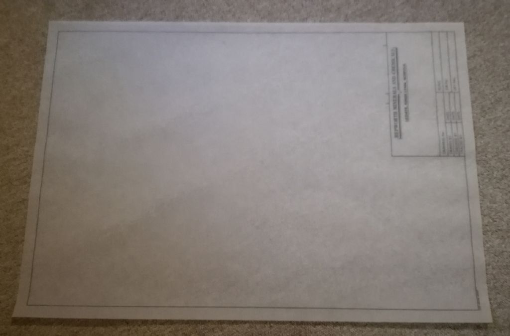
              Hi, I have never worked from an original drawing in all my working life, in my old job the drawings were done on translucent paper with a border and an information box in the lower right hand corner, below is a photo of a small portrait one.

              drafting paper.jpg

              Once the drawing was completed and checked, it would be fed into an A0 copying machine which had a roll of Diazo paper, which was sensitive to ultra-violet light. The drawing was driven through on top of the Diazo paper under ultra-violet fluorescent tubes, which the light would only pass through onto the paper where there where no lines of the drawing and then the exposed Diazo paper would pass through an ammonia vapour which would develop the drawing, which would be used in the workshop, the original drawings been keep flat in purpose made draws in the drawing office.

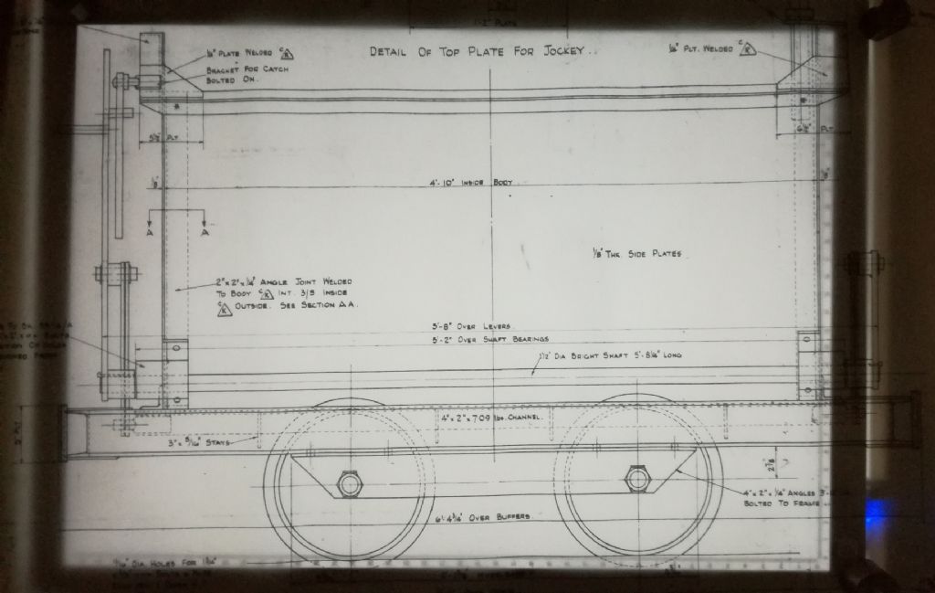
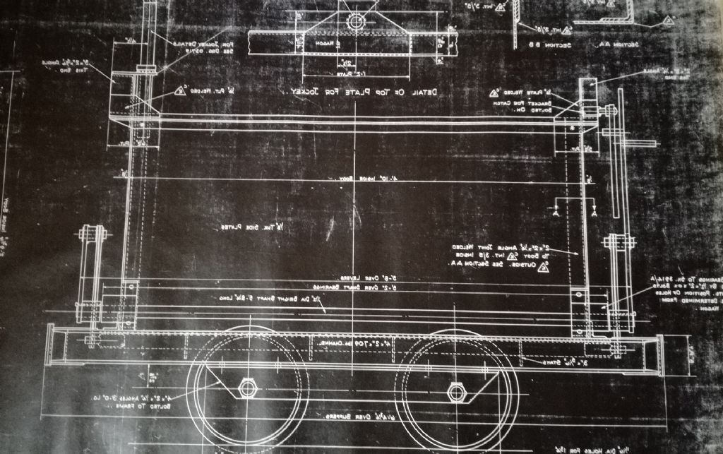
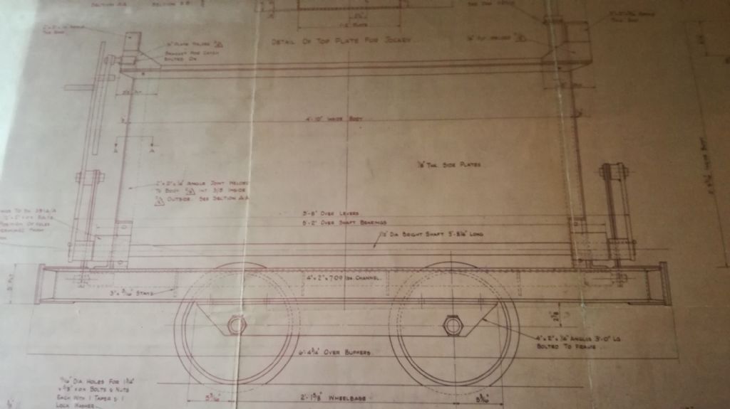
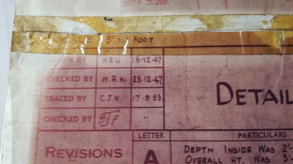
              I do have a couple of old drawings that were done in a similar manner I guess, this seems to be a two part copy paper where a master copy paper was made, the three photos below show a portion of a tracing from an original drawing. I don't know how the process worked, but I guess the original drawing was placed on the two part paper, the top part being translucent and the bottom one being sensitive ink, which would stick to the translucent one and produce a master copying print, which could then be copied onto a working drawing over and over again. The photo below show the translucent copy, a negative copy and a copy for the workshop. These were not made by the company I worked for, but from a company that supplied narrow gauge wagons.

              wagon 3.jpg

              wagon 2.jpg

              wagon 1.jpg

              The info box shows some dates when this was done.

              wagon 4.jpg

              In later years, this type was superseded by Auto CAD and ink jet printers.

              Regards Nick.

              Edited By Nicholas Farr on 11/01/2022 15:17:37

              #579850
              SillyOldDuffer
              Moderator
                @sillyoldduffer

                My Dictionaries cast light.

                Dr Ure's Dictionary of Arts, Manufactures and Mines:

                • Vellum is fine parchment.
                • True Parchment is made from animal skins,
                  • Basic writing parchment from sheep, or she-goat.
                  • Vellum, a heavier grade, is made from calves, kids, and dead-born lambs.
                  • drumhead parchment is made from He-goat, she-goat and wolves
                  • Battledores from Ass skin. (I think he means the paddles used in glass and bread making, not the early Badminton shuttle-cock.)
                • Parchment Paper starts as an unsized vegetable or rag paper, like blotting paper. After being treated carefully with Sulphuric Acid, and processes that remove all acidity the result 'undergoes a complete change.' 'The substance … exhibits in most of it's properties so close an analogy with animal membrane, that the name adopted appears fully justified'. Invented in the 1850s.

                Third Edn Shorter Oxford Dictionary allows Vellum to be made of paper as well as animal skin.

                My modern Dictionary of Science and Technology simply defines Vellum as being a fine writing paper.

                Pretty sure that the 'Vellum' used for technical drawing has always been Parchment Paper or similar well-made heavy writing paper, acid-free and long lasting, not animal skin. Mylar took over for technical drawing when dimensional stability is important because it resists stretching and humidity.

                Dave

                #579876
                JA
                Participant
                  @ja

                  I think true vellum is still being made and is used to record acts of Parliment.

                  I just remember linen. It was treated as a curiosity in the drawing training office. We were told the best thing to do with it was to wash it in hot water to get rid of the starch and then use it as a handkerchief. You can't do that with polyester film. I doubt if you can even get polyester film now.

                  JA

                  #579945
                  Bill Pudney
                  Participant
                    @billpudney37759

                    As Neil and others have said "Vellum" is a trade name for what is basically high quality tracing paper. Probably, mainly used by artists rather than draftsmen these days. I would imagine that the only people who use tracing paper/vellum or mylar these days would be those who produce "original" drawings on a drawing board in pencil or ink. In this context an "original" drawing is a valuable commodity. In any worthwhile organisation original drawings are kept under the control of a person whose job it is to ensure that "originals" are kept safely and not allowed out of the control of the drawing office. Drawings produced on CAD only have an electronic "original". Control of issue status is a major, some would say the major factor, especially with electronic drawings.

                    The printing process described by Nicholas Farr is the "dyeline" process. It can be used for making prints on either specially treated paper which is opaque, or secondary masters which are transparent. These are the drawings which would issued to a workshop make something. Then there is the secondary master type of print. This uses a specially treated mylar sheet (trade name "Ozalid" ) which can be used to produce duplicate originals, which can then be modified and given a new drawing number and a new issue status. Secondary masters can be used to produce dyeline prints. No doubt that this Dyeline process has become something of a niche process with the advent of CAD, but at one time any drawing office would have a dyeline printing machine, sometimes two or three. Now of course it is possible to take an electronic original to your local office supplies shop and they can print it on a large format photocopier.

                    cheers

                    Bill

                    Edited By Bill Pudney on 11/01/2022 21:42:50

                    ps I cannot get rid of the stupid yellow winking emoji thing

                    Edited By Bill Pudney on 11/01/2022 21:43:59

                    Fixed the emoji by putting a space between " and )

                    The forum editor generates emojis from certain character sequences. Supposed to help, I think it's an officious nuisance!

                    Edited By SillyOldDuffer on 11/01/2022 22:11:39

                    #579962
                    Bill Pudney
                    Participant
                      @billpudney37759

                      Thank you SOD!! You are quite right ….officious nonsense!!

                      cheers

                      Bill

                      #579981
                      PatJ
                      Participant
                        @patj87806

                        Vellum, as used on this side of the pond, is paper made from cotton fibers.

                        It can still be purchased in all sized including rolls for a plotter, and it is premium paper with a premium price.

                        It is similar to what money is made of, ie: you can get it wet and it will not disentigrate or deform, and will not be harmed by water if you dry it carefully.

                        Less expensive paper is made from wood fiber, and it will degrade and deform if exposed to water.

                        The vellum drafting paper is very tough, and can be purchased a little thicker than standard paper if desired.

                        You can erase pencil many times from vellum, and sometimes ink a few times from it, without abrading a hole in the paper.

                        We used vellum exclusively to create engineering drawings, both from an initial durability standpoint, and also from a long term storage standpoint. Vellum is great to work with.  I still have some of my vellum drawings from my later drafting classes in college.

                        The next step in the drawing elovlution I think was mylar, and we used double-side-matte finish, so it could be drawn on both sides (we sometimes did that in the day).

                        Mylar will last about forever, and my large clients still require all my final designs to be plotted on it.

                        36" x 50 yard mylar runs almost $400.00 per roll, so for me that is 75 plots, at $5.33 US per sheet.

                        I have projects with 100 sheets, so one must not forget to include the printing costs in the initial proposal.

                        In the old days of manual drafting, you had to be very careful to not burn through the top matte on mylar with the electric eraser, else you would have a bright spot where only a permanent marker could be used.

                        Mylar uses a special plastic eraser material.

                        Then came the "slick" system, which was clear plastic sheets with a photo sensitive coating.

                        You could create multiple copies of an architectural base plan, and distribute those drawings to all the various engineering disciplines.

                        A clean mylar sheet was placed over the slick, and then each discipline drew their own material on their own mylar sheet. When the architectural floorplan changed, one only had to pull out the slick, and insert a new slick.

                        Registration was accomplished using a "pin bar", which was a thin strip of stainless steel, about 36" long, with short pins protruding up every six inches or so.  All of the mylar sheets and the slicks had holes across the top.

                        Every now and then the slick registration would get off, and would cause terrible problems.

                        With slicks, you could also stack multiple drawings on top of each other, and print them on a vacuum printer, which was photo sensitive based printing.  This could be useful for cross-discipline coordination.

                        The original "blueline" prints (copies of vellum drawings) had a blue background with white lines.

                        When I started, they were using ammonia-developed bluelines to make copies, and the lines were blue, with a white background. The old blue background bluelines are very difficlult to read in my opinion.

                        With the advent of modern 2D CAD programs, which I started using in the early 1990's, we used virtual layers instead of physical slick/drawing layers.

                        2D CAD revolutionized how drawings were produced in the engineering world, but there were still many errors due to the fact that each view was drawn separate from all the other views.

                        In my opinion, 3D modeling is having a more profound affect on the engineering world than say the wheel, or fire.

                        3D models are interactive, and thus any change in the base model propagates immediately and automatically to every 2D drawing, with no human intervention required.

                        I use 3D modeling for model engines (and work projects), and I can run an engine virtually, and test for interferences.

                        If my 3D model is not absolutely correct, the virtual model will not run, so I know when I try new engine designs that they will run flawlessly when constructed.  There is all sorts of data that can be extracted from a virtual model, such as mass, balance, velocity, acceleration, etc., and so one can measure the vertical and horizontal forces being generated from a virtual engine that is being run, and find out how badly it will vibrate.

                        .

                        Edited By PatJ on 12/01/2022 03:24:54

                        Edited By PatJ on 12/01/2022 03:25:45

                        Edited By PatJ on 12/01/2022 03:26:32

                        Edited By PatJ on 12/01/2022 03:27:17

                        Edited By PatJ on 12/01/2022 03:28:42

                        Edited By PatJ on 12/01/2022 03:33:56

                        Edited By PatJ on 12/01/2022 03:34:56

                        Edited By PatJ on 12/01/2022 03:51:53

                        #579984
                        PatJ
                        Participant
                          @patj87806

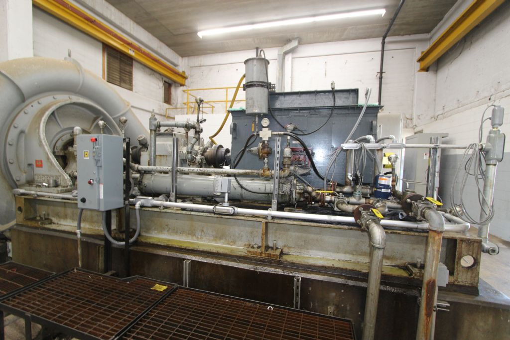
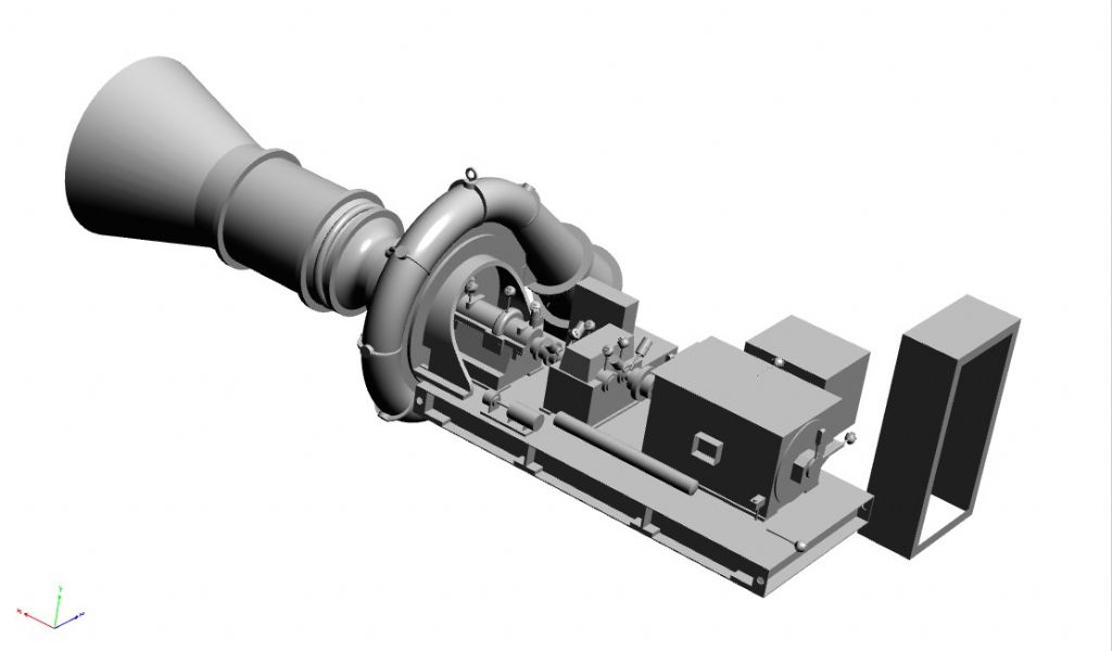
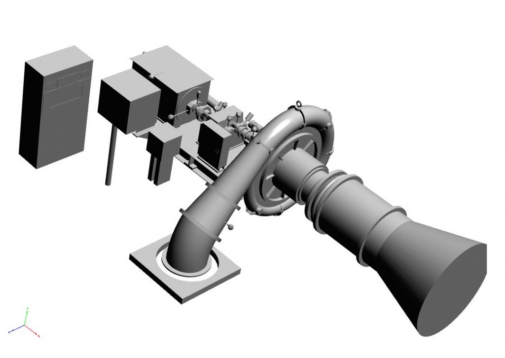
                          Here is a project for a wastewater system aeration blower that I did a few years ago.

                          1,500 hp 5KV motors. We replaced the control systems for six of these with modern PLC controls and SCADA.

                          I made some calipers about six feet long, and took off the measurements from one of these blowers, and put it into a 3D model.

                          I was able to send this model to various parties, where they could pan/tilt/zoom on the model to see all the various sensors and their location.

                          These days, the trend is to use a scanner, and thus what took me perhaps one day to create in 3D can be created in a couple of minutes.


                          img_8930.jpg


                          image24.jpg


                          image25.jpg

                          Edited By PatJ on 12/01/2022 03:45:16

                          Edited By PatJ on 12/01/2022 03:46:12

                          #579987
                          PatJ
                          Participant
                            @patj87806

                            In the old days, people would save all of their engineering drawings, and so an engineering firm would typically have a large storage room full of racks or drawers of drawings, and boxes stacked to the ceiling containing specifications (on had to watch the floor loading).

                            I accumuated many full sized drawing, and eventually had to begin discarding them.

                            I started plotting archive drawings at 1/2 size.

                            These days, I keep 11"x17" final plots in binders on the shelf, per project.

                            With 1200 dpi resolution on copy machines, you can easily read a 24"x36" drawing reduced to a 11"x17" print.

                            The new copy machines will copy/print/scan in 1200 dpi, and I use mine for a printer too.

                            I can scan directly to a PDF file on a flash drive that is plugged into the copy machine, or print from a pdf file.

                            The first word processor computers (IBM) that our firm had 12" diameter floppy disks (I still have one of these machines). Computers progressed to hard drives, which were prone to failure.

                            The computers I buy now have solid state drives (no moving parts).

                            I use four flash drives for work, and carry two on my keychain, each at 1TB, and they basically contain every drawing I have ever made, and every photo I have ever taken.

                            When I began in engineering in 1980, the only computers they had were mainframes, with line printers, and IBM punch cards. There were no screens or mice. The program we used was FORTRAN, and I still have my compiler somewhere.

                            When I started working in 1985, we had a mainframe with four "dumb" CRT screens (small monochrome units) and keyboards, and again used FORTRAN. Nobody got out of engineering school without at least learning FORTRAN, but I also took an assembly language class, and created assembly language programs that ran on a PDP-11 computer (a dinosaur, but a reliable computer).

                            The times, they have changed………..

                            Seems like yesterday.

                            .

                            Edited By PatJ on 12/01/2022 04:33:38

                            Edited By PatJ on 12/01/2022 04:34:38

                            Edited By PatJ on 12/01/2022 04:54:20

                            #579988
                            PatJ
                            Participant
                              @patj87806

                              I have a 1200 dpi color scanner, and three 1200 dpi inkjet printers.

                              These days, most engineering work is paperless.

                              Drawings are created in CAD, and plotted to PDF files.

                              Specifications are also in PDF format.

                              When a project is bid, no physical prints are issued; everything flows to the various people via the internet and PDF files.

                              Generally there will be one set of printed drawings on the job site, in the contractor's job shack, used to record "as-built" changes.

                              The supervising contractor will have an pad type computer, and when discussing the project with him, he pulls up drawings on the screen and pans through those, which are high resolution (1200 dpi).

                              I refuse to "go ipad", LOL, but many have gone that route.

                              I carry an 11"x17" set of drawings to the job site.

                              I still primaryily use AutoCad to make 2D drawings, but I also use Solidworks to create 3D models.

                              A buddy of mine who is a mechanical engineer has used an integrated 3D building modeling system (Autodesk's version) for many years, and his 3D models appear as a part of one large model that contains all the disciplines. The 3D model can change dynamically, as people all over the country work on it in real time (in the clouds, as they say).

                              I am not "going BIM" either. I will retire before I do that.

                              BIM = building information model

                              BIM is a bridge too far for me.

                              The mandatory annual fee to run BIM software can approach $2,000.00 per person.

                              I use a perpetual liscense of AutoCad 2004, and it works well with 2D drawings.

                              For one-off 3D models, I use Solidworks 2012, which is also a perpetual license.

                              .

                              Edited By PatJ on 12/01/2022 04:50:22

                              #579989
                              PatJ
                              Participant
                                @patj87806

                                One more thing about drafting vellum (made from cotton fibers).

                                It is translucent, and so allows blueprint copies to be made from it (not that anyone makes blueprints anymore in the modern world).

                                .

                                #580002
                                norm norton
                                Participant
                                  @normnorton75434

                                  Lots of technical comment. The original question was along the lines of 'can these two drawings in ME be described as art?'.

                                  In my view, yes, they are most attractive to look at and enjoyable. Are they technically imperfect, do they have flaws – yes that is inevitable as they are hand drawn to that individual's aesthetics. And that is what makes them special.

                                  I thoroughly enjoy seeing hand drawings in ME, and equally shudder at the thought that the editor has converted many into cold, sterile, technically correct drawings.

                                  CAD has done a great service in making dimensionally accurate drawings easily achievable, and I use it for that, but the result is cold and mechanical, and rarely beautiful.

                                  #580011
                                  Michael Gilligan
                                  Participant
                                    @michaelgilligan61133
                                    Posted by norm norton on 12/01/2022 09:22:36:

                                    Lots of technical comment. The original question was along the lines of 'can these two drawings in ME be described as art?'.

                                    .

                                    Fair comment, norm yes

                                    But, having never seen the drawings in question, I could only remark upon ‘Vellum”

                                    MichaelG.

                                    .

                                    With many thanks to PatJ for the information.

                                    Edited By Michael Gilligan on 12/01/2022 09:59:48

                                    #580022
                                    Martin Kyte
                                    Participant
                                      @martinkyte99762

                                      I would have some of the classic draughted pencil drawings from old engineering books on my wall. Inddeed some old books have pages missing where this has actually been done. Grimthorpe's treatise on Clocks Bells and Watches is a point in case. It is supposed to have a fold out drawing of the Westminster Clock (aka Big Ben,yes I know it's really the bell) but in most copies this has been removed and sold separately.

                                      Not sure I would want any of the CAD drawings on the wall even the 3 D renderings.

                                      On a slightly different track a friend had an interesting story back to the period where their company was transitioning from drwing boards to CAD. The employed a lady who had been a tracer to digitise the old drawings. Essentially clicking on the ends of lines etc and generating computer input. For printout they used an HP pen plotter which could do A0 sheets by moving the pens in the X direction and rolling the drawing sheet in and out to generate the Y axis. When the printed any of the newly digitised drawings it took an age as the plotter spent all its time drawing a bit and then moving to the other corner of the sheet and doing a bit there and so on. Things were plotted in the order of input. When she was asked why she had done thing in this way instead of systematically moving from the top to the bottom in one pass, she said that as a tracer, you had to do a bit and then do somewhere else whilst the ink dried otherwise you got smudges. That was the was she always did it then, so she just carried on the same when doing the digitising.

                                      regards Martin


                                      Edited By Martin Kyte on 12/01/2022 10:22:23

                                      #580039
                                      PatJ
                                      Participant
                                        @patj87806

                                        When 2D CAD systems began, there were no CAD standards, and so each draftsman did their own standard, which was incompatible with anyone else's.

                                        It became a turf war thing, and the drafting folks would introduce CAD tricks into their drawings, that only they understood, so that you had to keep using one particular drafter after initially beginning a project with them (job security they openly claimed).

                                        Each draftsman would come up with their own symbols, again without adhering to any standard.

                                        By about 1995, I was in a position to be supervisor for a department, and I forced all of the drafters to use exactly the same CAD symbols, layers, linetypes, screen colors, legends, etc.

                                        One drafter refused to go along, and insisted on using his system no matter what. We had to fire that guy.

                                        The other drafters often went along with the standard sytem after a prolonged period of wailing and complaining. Within about a year, I could take any drawing to any draftsperson (we had women and men), and I could get consistent results back.

                                        Then we had to drill into each draftsman's drawings and get rid of all the tricks.

                                        We came up with one simple method for displaying all drawing information, and did not allow any tricks that only one draftsman understood or used.

                                        We created an fly-out menu for symbols, that automatically put the symbol on the corrrect layer, using the correct linetype and color. No more getting a symbol on the wrong layer, or plotting to light or heavy.

                                        At one company, we used different CAD software for different clients, ie: some clients used AutoCad, and some used VersaCad. It took several years to convince management to standardize on a single software (in this case AutoCad).

                                        Then there was a battle between AutoCad, which was used mostly in the Architectural world, and a totally different CAD system, which I forget the name, but it was dreadful and totally counterproductive to use.

                                        If you wanted to do government work, you had to use the inefficient CAD software, and charge enough extra money to cover the inefficiency.

                                        There are good CAD standards now.

                                        I have my own, but generally somewhat adhere to some of the national standards.

                                        The bottom line is how much work can you produce in a give amount of time, or in other words, how efficient is your CAD system.

                                        Nothing to do with drawings as a work of art, but in the beginning of CAD, it was a proverbial Tower of Babel, and pitched battles went on for years to get it all worked out, in case anyone wants to know.

                                        .

                                        Edited By PatJ on 12/01/2022 11:35:53

                                        Edited By PatJ on 12/01/2022 11:37:16

                                        #580041
                                        Michael Gilligan
                                        Participant
                                          @michaelgilligan61133
                                          Posted by Martin Kyte on 12/01/2022 10:20:39:

                                          […]

                                          it took an age as the plotter spent all its time drawing a bit and then moving to the other corner of the sheet and doing a bit there and so on. Things were plotted in the order of input. […]

                                          .

                                          Not entirely true, Martin

                                          HPGL has it’s own idea of optimisation, and will behave like that regardless of the original order of input.

                                          The Roland DXY-1100 flatbed behaves in a similar fashion.

                                          MichaelG.

                                          #580044
                                          Martin Kyte
                                          Participant
                                            @martinkyte99762

                                            I do hope you realise I am just repeating the story. The intresting point was the tracer worked as she always had.

                                            However our own plotter used for plotting PCB transparencies did follow the input file including redrawing lines where there were two lines between two points. That used to gum up the pens something chronic, so I'm not sure I entirely believe you Michael.

                                            regards Martin

                                            #580048
                                            Michael Gilligan
                                            Participant
                                              @michaelgilligan61133
                                              Posted by Martin Kyte on 12/01/2022 11:56:31:

                                              I do hope you realise I am just repeating the story. The intresting point was the tracer worked as she always had.

                                              […]

                                              However […] so I'm not sure I entirely believe you Michael.

                                              .

                                              (a) Understood

                                              (b) That is entirely your choice, Martin

                                              .

                                              MichaelG.

                                              .

                                              Edited By Michael Gilligan on 12/01/2022 12:07:23

                                              #580049
                                              Ches Green UK
                                              Participant
                                                @chesgreenuk

                                                PatJ,

                                                Thanks for that useful brief on different CAD systems' 'standards'.

                                                Are there actually any 2D CAD packages that rigorously follow

                                                – ISO 128 – https://en.wikipedia.org/wiki/ISO_128 or

                                                – BS 8888 – https://en.wikipedia.org/wiki/BS_8888 ?

                                                Ches

                                                Edited By Ches Green UK on 12/01/2022 12:05:32

                                                #580055
                                                Martin Kyte
                                                Participant
                                                  @martinkyte99762
                                                  Posted by Michael Gilligan on 12/01/2022 12:02:57:

                                                  Posted by Martin Kyte on 12/01/2022 11:56:31:

                                                  I do hope you realise I am just repeating the story. The intresting point was the tracer worked as she always had.

                                                  […]

                                                  However […] so I'm not sure I entirely believe you Michael.

                                                  .

                                                  (a) Understood

                                                  (b) That is entirely your choice, Martin

                                                  .

                                                  MichaelG.

                                                  .

                                                  Edited By Michael Gilligan on 12/01/2022 12:07:23

                                                  I meant that that may be the case sometimes, but our system certainly operated sequentially maybe VuTrax had it's own plotter driver built in. I have no idea what my friends system used.

                                                  regards Martin

                                                  #580150
                                                  Michael Gilligan
                                                  Participant
                                                    @michaelgilligan61133

                                                    Not for anything but the joy of reminiscing: **LINK**

                                                    HP 7475A Plotter and HPGL Demo

                                                    MichaelG.

                                                    #580167
                                                    SillyOldDuffer
                                                    Moderator
                                                      @sillyoldduffer

                                                      With my ex-programmer's hat on, the order in which lines are drawn by a plotter are at the whim of the programmer.

                                                      Basically lines are drawn between two coordinates, in a colour, with pen up or pen down. When plotters first appeared, memory was small and expensive, so simplicity ruled: lines would be drawn in the order received. This has several disadvantages such as smudging, stop-starts, long jumps, and other inefficient movements.

                                                      When a plotter or other device has lots of memory and compute power, all the lines can be captured in a list and the program can traverse it in more-or-less complicated sequences, to improve performance and economy. For example, the programmer might:

                                                      • Save time by sorting the list so contiguous lines are drawn end to end in sequence
                                                      • Improve ink efficiency by printing lines colour by colour
                                                      • Avoid smudging by deferring lines that cross other lines until the ink has had time to dry
                                                      • Remove duplicate lines and overlapping segments
                                                      • Minimise head movement by drawing all the lines in the local area.
                                                      • Minimise head movement by drawing aligned lines in the same movement.

                                                      Exactly what's done depends on the device. A pen plotter might physically lift and drop a pen, or- more likely these days – the whole output might be rasterized. In that case, there's no obvious relationship between the original commands and the print head.

                                                      Dave

                                                    Viewing 25 posts - 26 through 50 (of 70 total)
                                                    • Please log in to reply to this topic. Registering is free and easy using the links on the menu at the top of this page.

                                                    Advert

                                                    Latest Replies

                                                    Home Forums Model Engineer. Topics

                                                    Viewing 25 topics - 1 through 25 (of 25 total)
                                                    Viewing 25 topics - 1 through 25 (of 25 total)

                                                    View full reply list.

                                                    Advert

                                                    Newsletter Sign-up