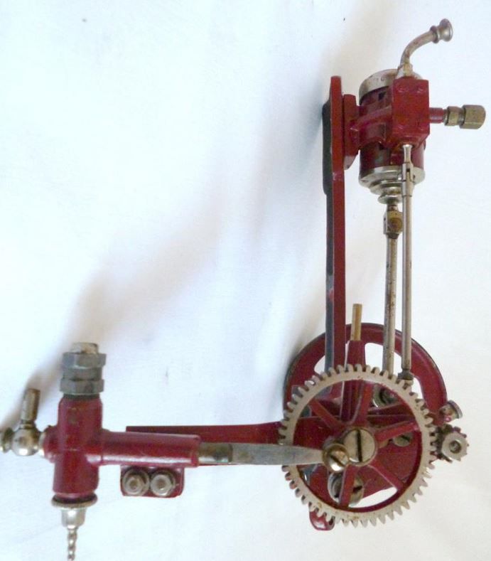
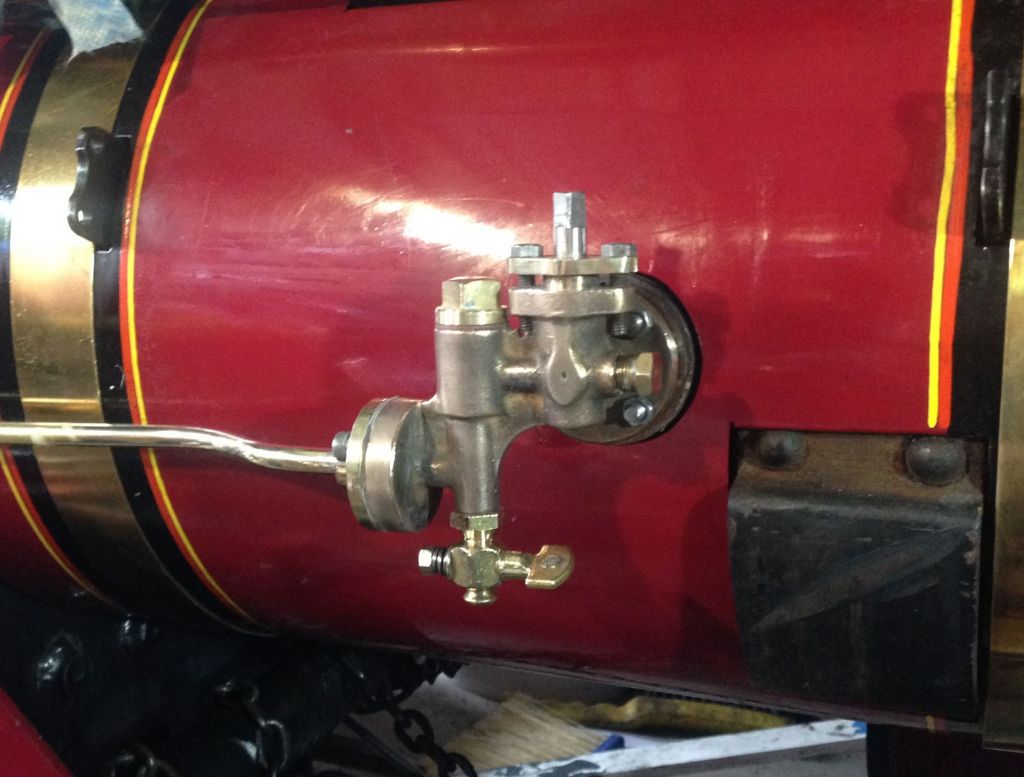
Normal practice on both full-size and miniature road steam vehicles is a feed-pump driven from the crankshaft, but how reliable is this on a fast running engine (say, 400 rpm)?
I was discussing this with a friend who'd been steaming his 3" scale traction-engine, and he said it does run noticeably faster than a 4" engine.
Also, the pump eccentric was quite unevenly worn, due, we concluded, to the way it is loaded, especially when feeding water against boiler pressure.
So, Q1: if the engine itself is designed to run at high speed does the pump become inefficient if directly driven, so better driven via a reduction gear?
.
Q2: A traction-engine needs only a short bypass pipe as the pump is above the tank. If the tank is a long way away, on a wagon, does the bypass pipe need go all the way back there or can it simply go to a Tee-piece on the suction pipe and just circulate the water locally?
.
I add that I have installed a hand-pump in the tank at the rear of the vehicle; but will be supplying the injector and feed-pump through a common 15mm pipe (domestic plumbing material) from the tank to a Tee-piece and 15mm – 1/4" pipe adaptors; near the two devices a little aft of the front axle.
I have not yet determined the eventual location of the pump on the model, and have no idea where it was on the original wagons.
Many full size engine have a pump driven from the crankshaft, others from a secondary, slower shaft but that run much slower than a model. ~250 RPM. If run too fast the piston may not completely fill and just have a vacuum in the cylinder and not pump water.
My 6" Ruston has a pump connected to the crankshaft and will pump at 350 RPM but is not as efficient as running a bit slower. The pump gets a loud rattle noise at high speed when the balls in the clacks are hammered back and forth as the valve is open and closed. I normally slow down when adding water to the boiler.
All of the engines that I have seen have the bypass, returning back to the tank.
If the pump is attached to or near the boiler, locally recirculating the same small amount of water might raise its temperature enough to cause cavitation in the pump on the suction stroke as gasses/vapour flash off under low pressure conditions. High temperature with low pressure makes it worse. This could cause the pump to lose suction and stop feeding water to the boiler, or at least slow down the delivery rate. Cavitation can be what causes that rattling noise in pumps that are losing suction.
OK, not on a traction engine, but my steam launch has two pumps driven by levers off the cross head, so the pumps are working at engine speed. The rams are about half inch diameter and the stroke is about two inches. The bypass is just back into the suction side, and I would say that the main drawback of this is that you can't see the water squirting back into the tank, which tends to assure you that the pump does work. I've got a couple of small pressure gauges on the delivery side which allows me to see the pressure pulses when they are pumping, but theses need to be turned off mostly to avoid thrashing the gauges to death. The copper pipes too and from the bypass valves are long enough that I don't think heating of the circulating water is going to be a problem. The engine runs at up to about 600rpm at full speed, so is often cruising at 4 to 5 hundred rpm
The engine speed pumps do have their problems, the main one I have had is the seals on the rams not lasting very well. They started out as standard O-rings, and were replaced with hydraulic type U seals. Those seem to last better, but not as long as I would like. It may be that the initial finish on the bores was not as good as would be nice, but they should have polished themselves by now. The ball valves have stood up to it really well. The seats were initially burnished with a spare ball held in a recess in a piece of brass rod. The lift is limited as it should be.
Long term I would like to come up with a geared down pump setup, but I can see how this might not be ideal for a scale model like the traction engine guys have.
As Paul says many full size gear down the pump drive and it is also common on models the Burrell GMT being a popular one. You even find it on things like the Stuart D10 and the old steam toys by the likes of Ernst Plank, the latter having quite a reduction ratio.
As for plumbing my Fowler has the bypass valve on the end of the pump and is just a short drop back into the tender. Whereas the Minnie has the valve towards the rear of the tender and pumps back below water level, not a bad thing what with the boiler mounted pump as that would get even hotter if the bypass was just circulating a small volume of w ter
Most single cylinder positive displacement pumps will not run at high speed happily. Several things to cosider:
1 The valves will not open or close quick enough, so the volumetric effy. Drops away – it pumps less.
2 The water columns on inlet and outlet cannot accelerate and decellerate quick enough to keep up with the pump. That leads to all sorts of banging and knocking & premature valve wear. Possible fixes are bigger pipework, shorter pipework and air vessels on inlet and/or outlet.
Most high speed PD pumps use multiple cylnders. Go look at a pressure washer chatting away at 3000 rpm, but with a triple diaghragm or piston pump.
Triumph motorcycles had plunger oil pump driven off the camshaft, so ran at 3000 rpm. However you need careful design to avoid inertial issues. I suspect this gets more difficult as size goes up, motorbike oil pump is quite small. Better to run more slowly with a bigger pump. You want light valves with restricted lift,but if you overdo it you restrict the flow.
Having the bypass visibly return to the tank doesn't mean you know its working. It might pump away merrily at low head but fail to deliver to the boiler. I've seen that on a loco at our club. However it's better than nothing, if it won't pump back to the tank it certainly won't pump to the boiler.
to John Olsen – I was asked to design a Repair for a Quadruple Adhesive Dispenser used in a Fluorescent Light Factory. Four Bases (the metal part at the End of the Lamps with the Pins in it) at a time would be indexed thru the Machine by a Walking Beam and at a Dwell in the Motion four Nozzles would enter the Base and a specific amount of "Base Cement" would be dispensed. The total Cycle Time was on the order of 2 seconds.
The Body of the Dispenser was a very complicated Part machined from a Block of Aluminum. It had ~1" diameter Air Cylinder Bores bored directly in the Body. These Bores would become scored and led to scrapping of the Part. The problem was the Cylinder Bores were so close to each other one could not bore them out and fit Sleeves. The Bores were pitched closely to match the Walking Beam and the Cam driven motion of the Machine. Changing the Pitch would lead to all sorts of non-standard Parts.
The Solution I came up with was to line them with the very thin drawn Stainless Steel Tubing used by BIMBA brand "Original Line Air Cylinders". I purchased four Air Cylinders from them with about 2" of extra Stroke and had a Machine Shop carefully cut the Cylinder Tubes from them. The Wall Thickness is on the order of .030". The Tubes were Loctited into the Body (after a very small required sizing boring). I added non-metallic Wear Rings to the Pistons (they required re-sizing anyway) and put it into production. These Units ran almost 24 hrs / Day 6-7 Days a Week for 10 years.
We used BIMBA "Original Line Air Cylinders" all over our Manufacturing Plants, often running in 1 sec total Cycle Time Applications to operate Part Release Gates. Rarely did one fail before completing 10 million Cycles. Some seemed to run forever.
The point is – I would recommend lining a Pump Bore with their Cylinder Wall Tubing. The Air Cylinders are inexpensive.
I will have anyway to make a functional driving-platform very different from the static "show" load platform that looks like a lorry platform, so arranging some way to view the bypass outlet will not be difficult.
The pump will not be attached to the boiler, but to either the chassis or the engine enclosure.
'
Paul –
It is a representative rather than fine-scale, 4" -scale Hindley "Light Delivery Van" , to use the manufacturer's own brand name for this relatively small vehicle. The originals had a capacity of about 2 or 3 tons.
Its particularly unique features are a locomotive-type boiler but with vertical-cylindrical firebox (I believe some Shay locos and a French make of portable engine had similar); and an enclosed inverted-vertical engine standing through the chassis between the crew seats.
A layout giving some very odd, unexpected design problems, since I have no original drawings for it, and as far as is known, none exist. Just contemporary advertising photographs and a few dimensions by the builder and by trade-magazine reviewers .
The model is about five feet long and a shade under two feet wide: scaled as best I could from photographs, and slimmed slightly so it would fit through my – and its – first home's front door.
Nigel: Good luck with your project. I would be interested in seeing the build of your van. (as would others)
Duncan: ( Having the bypass visibly return to the tank doesn't mean you know its working. It might pump away merrily at low head but fail to deliver to the boiler). My injectors originally had a plug at the bottom and I have added a bleed valve for this reason, to verify if the pump is working. Also a second bypass valve from the pump that shoots sideways to easily see if the pump is working while I am driving. (and to squirt onlookers)
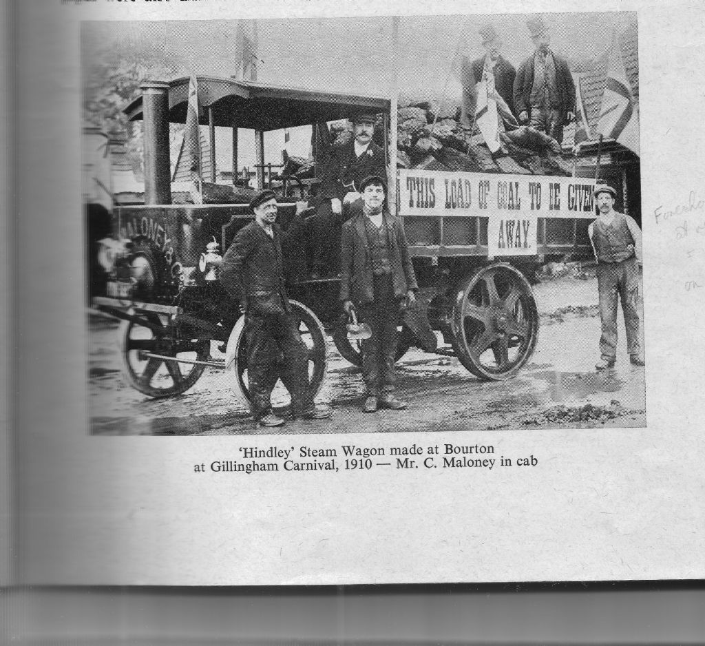
The original vehicles were basically flat-beds but other body styles could be fitted, and the photo below from the Dorset Year Book 1977 is the one that inspired me. The cab, such as it is, was an optional extra!
The boiler-testers in my club tend to prove if a pump actually is putting water in the boiler is working by very carefully feeling its temperature! Fine on a traction-engine but not so easy on a locomotive unless tested on a rolling-road.
Otherwise it is very much a matter of watching the water-gauge and pressure-gauge.
I did'nt explain the second bypass clearly. It is tee off the pressure pipe between pump and injector and runs up to the operators position and terminates with a ball valve. After closing the bypass valve to the tank, open the ball valve and check if water comes out under pressure (or squirt someone)
Squirting someone would seem a certain way to know the pump is working!
Hidden on that historical photo, the tank is tucked away behind the rear axle. I have given my model a hand-pump in the tank, and its handle needs a large slot with coaming in the lid. As this needs be readily accessible from the driving platform, the sensible, and simple, approach is place the bypass outlet visibly just below the rim of the slot, as on many miniature locomotive tenders.
.
Charles Maloney's businesses were evidently successful and perhaps he liked to treat his employees well, for all the Hindley publicity suggests the canopy was an optional extra I am copying. Bling too, as few if any other photographed examples show a polished capuchon: I have replicated the standard chimney's half-round beading, all painted. The side-lamps are Hindley standard, but that big headlamp on a crude wooden frame looks like an owner's modification.
.
(I have built a plain, flat-bed platform for static display. Held by 6 M6 coach bolts that are not too intrusive or unlikely, it is reasonably realistic with separate planks on a wooden frame. I gauged likely plank and frame sizes from examining preserved and modern goods vehicles, and dividing by three.
I painted it, but later realised it would look better if I removed the paint on the floor area and replaced it with timber preservative. A coarse sanding-disc left shallow arcs, which l kept, so that the treated floor resembles the circular-sawn, creosoted planks likely to have been fitted to the originals built >100 years ago.
The frame and head-board stay painted, as appears common on preserved full-size lorries)
Author
Posts
Viewing 15 posts - 1 through 15 (of 15 total)
Please log in to reply to this topic. Registering is free and easy using the links on the menu at the top of this page.