EMCO Rotary / Indexing table

Advert

EMCO Rotary / Indexing table

Home Forums Manual machine tools EMCO Rotary / Indexing table

Viewing 11 posts - 1 through 11 (of 11 total)
  • Author
    Posts
  • #439710
    Raphael Golez
    Participant
      @raphaelgolez

      Hi can someone help with the manual for the Emco 6 inch Rotary Indexing table. I believe the gear ratio is 40:1.

      I understand that you can rotate the main worm gear out of engagement and make the table free to rotate but what puzzle me is the lock pin on the back left side. Is this just to lock the table? There is a separate table lock located on both side though. I opened the back cover plate and this locks a smaller gear, would this be direct indexing instead? If so its near impossible to tell the gear tooth engagement. If anyone who is familiar with this mechanism can please shed more light.

      Lastly, can someone help with the plate indexing chart on this. I understand that it would likely be the same as any standard 40:1 but it would be good to see and compare info on the WWW.


      Thanks in advance,

      Raphael


      Edited By RAPHAEL VAL GOLEZ 1 on 01/12/2019 18:20:12

      Advert
      #13715
      Raphael Golez
      Participant
        @raphaelgolez
        #439724
        Joseph Noci 1
        Participant
          @josephnoci1

          Hello Raphael.

          I have some zipped BMP image files of the FB2 manual, in which the rotary table is well described.

          The images are not great, but are legible/usable.

          PM me with your email and I will email them to you.

          The 'Lock pin' you speak of is used to 'pin' the rotary table in fixed indexes – if I remember correctly – in 15degree increments, in the perimeter of the rotary table. If using the index discs or dividing plates, that lever is pulled out and rotated to the disable position, so that you can index incrementally. The other two levers are to lock the table in position while machining.

          To turn the table freely, loosen and back off the Cap Screw seen near the worm shaft exiting the table block. Then rotate the worm away from the table gear by rotating the dividing plate counter-clockwise.

          Joe

          fix typo

          Edited By Joseph Noci 1 on 01/12/2019 20:25:17

          #439734
          Raphael Golez
          Participant
            @raphaelgolez

            Thanks Joe,

            I have seen your work on this table with your indexing motor and adjustable grip tru style chuck mount. Really top notch.

            Thanks for the clarifications. I will use this purely for indexing manual work. Do you have the chart for this? Or I can use a generic 40:1 chart?

            I will PM you my email. Thanks in advance!

            Cheers,

            Raphael

            #660115
            Jeffery Morris
            Participant
              @jefferymorris50968

              Joe,

              I know this is an old post, but I have a couple of questions regarding the lock pin. I looked at your pic's and when you added the stepper motor it looked like you removed the handle and locking pin parts. you wouldn't happen to have pic's of them, would you? I picked up a v10-p lathe and this rotary table was included. it has a plug where the handle should be. i found the handle in the toolbox but it appears broken and I don't see anything in the hole. I'd like to see the parts that make up this part of the assembly.

              thanks

              jeff

              #660131
              Joseph Noci 1
              Participant
                @josephnoci1

                Hello Jeff.

                I will have a look tomorrow. I don't believe I took photos of those parts, but I may have a manual somewhere.

                Joe

                #660146
                Joseph Noci 1
                Participant
                  @josephnoci1

                  Hi Jeff,

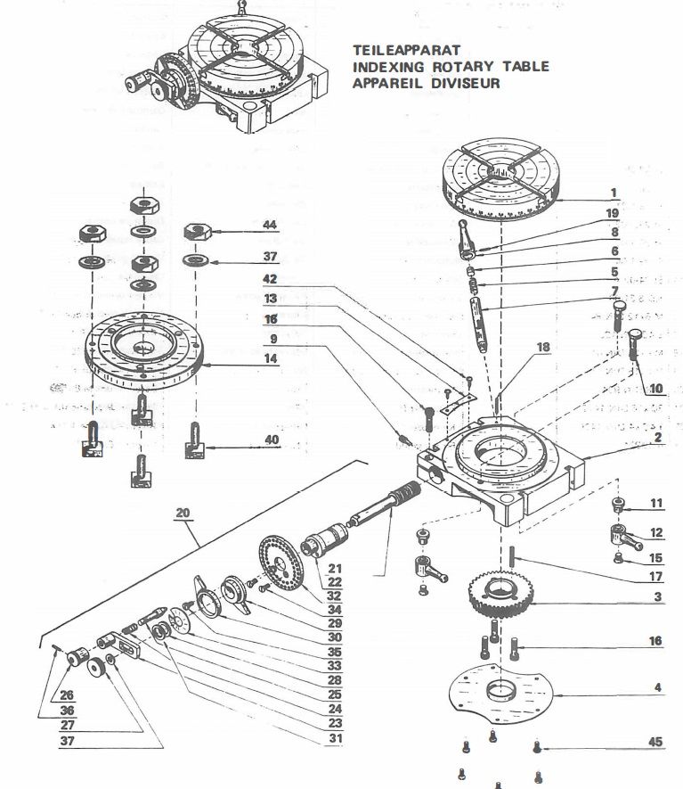
                  I don't have photos I fear – there are part breakdown docs on the web, google will find them, but most are in French or German, and the part drawings are not very clear it seems…


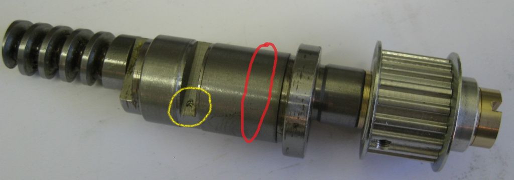
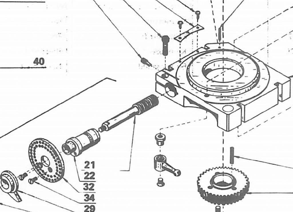
                  This photo shows where the pin – item 9 in parts list, impinges on the point ringed yellow. the pin is screwed in, rotating the eccentric which snugs the helix up against the ring gear to take up play and backlash. The red ring is the surface that is clamped in the table body, by cap screw item 16, preventing the eccentric from rotating. To relieve the helix from contact with the ring gear, loosen cap screw 16 and rotate the eccentric away from pin 9, and the helix rotates away and free from the ring gear. Pin 9 slide in the slot ringed yellow, 'up' towards the top end as the eccentric is rotated, Pin 9 keeps the eccentric from pulling out of the table.

                  worm  marked.jpg


                  rotary table parts.jpg


                  rotary table parts2.jpg


                  For interest, some div. head calculators…

                  Div head spreadsheets1

                  Div head Spreadsheets2

                  Another Calculator


                  edit- smileys…

                  Edited By Joseph Noci 1 on 15/09/2023 08:02:37

                  #660169
                  Jeffery Morris
                  Participant
                    @jefferymorris50968

                    Joe,

                    Thanks for all the information. I was actually looking for info on this part of the parts diagram:

                    Here's my broken piece that I have:

                    Parts 5,6,7,and 8

                    Jeff

                    #660181
                    Joseph Noci 1
                    Participant
                      @josephnoci1

                      Sorry about that – without reference to the actual parts it becomes anyone's guess…

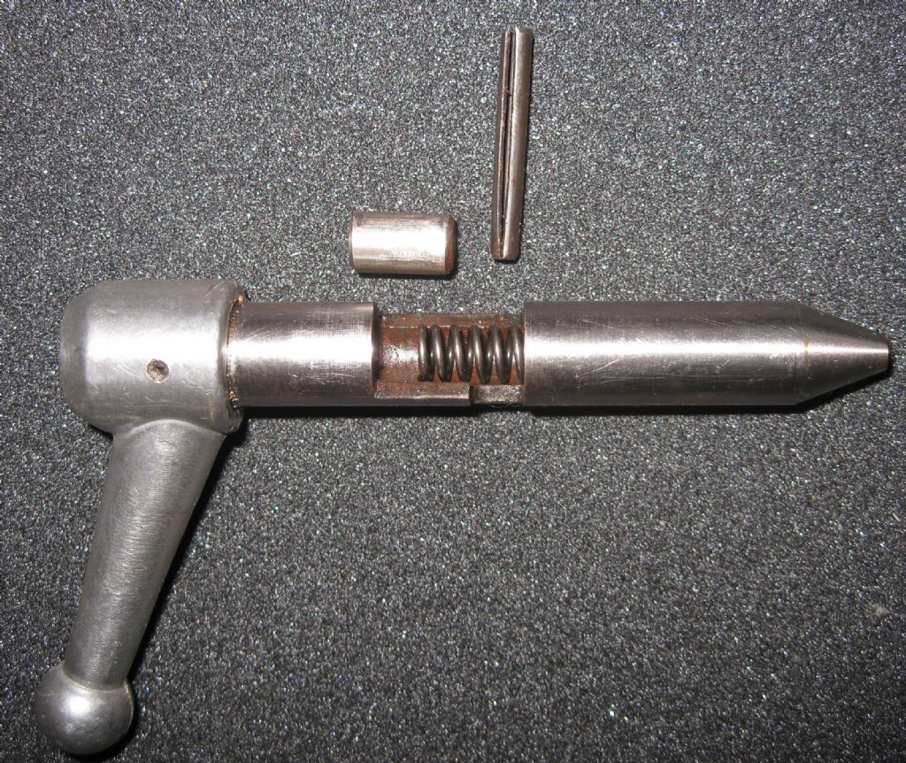
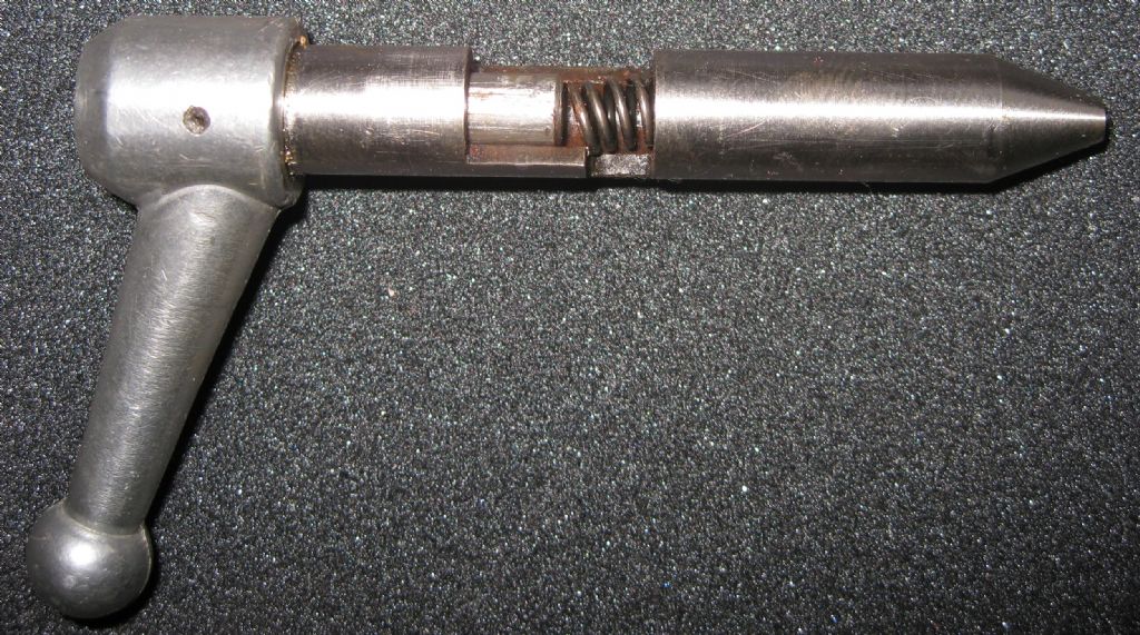
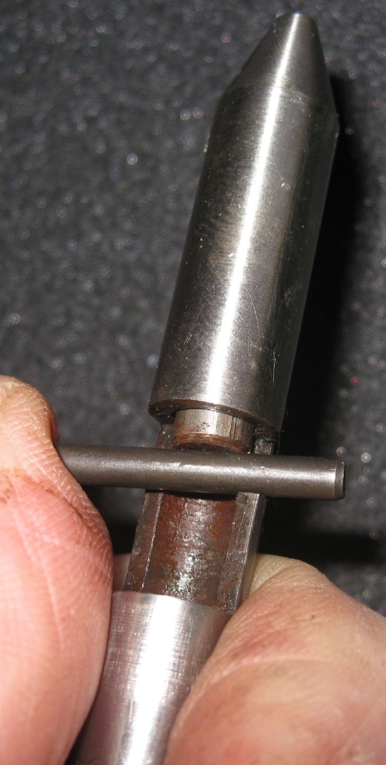
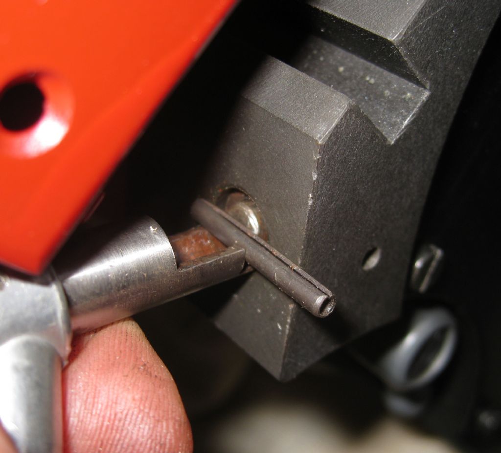
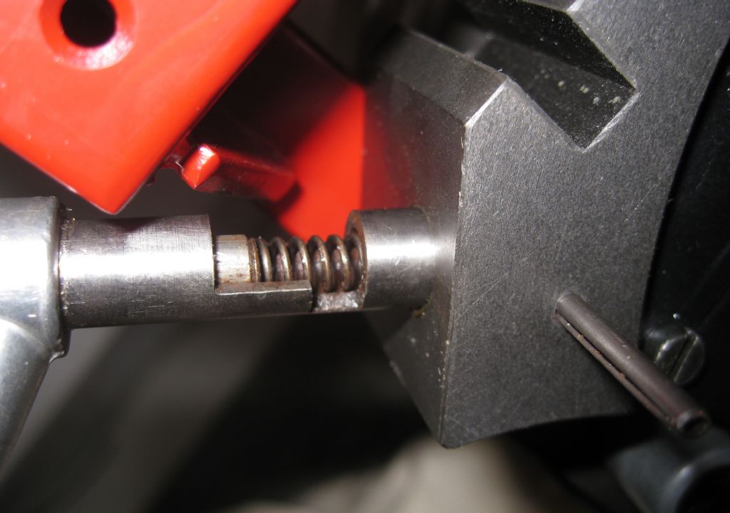
                      See photos below of the part – if you need a dimensioned drawing, let me know, I will see what is possible..

                      lever1.jpg

                      lever2.jpg

                      lever3.jpg

                      lever4.jpg

                      lever5.jpg

                      lever6.jpg

                      #660184
                      Michael Gilligan
                      Participant
                        @michaelgilligan61133

                        Wow !

                        … a cunningly designed stress-raiser if ever I saw one surprise

                        MichaelG.

                        #660276
                        Jeffery Morris
                        Participant
                          @jefferymorris50968

                          Joe,

                          thank you so much!! those are the pics I was hoping to see. Now I understand how it works!!

                          thanks again!!

                          Jeff

                        Viewing 11 posts - 1 through 11 (of 11 total)
                        • Please log in to reply to this topic. Registering is free and easy using the links on the menu at the top of this page.

                        Advert

                        Latest Replies

                        Home Forums Manual machine tools Topics

                        Viewing 25 topics - 1 through 25 (of 25 total)
                        Viewing 25 topics - 1 through 25 (of 25 total)

                        View full reply list.

                        Advert

                        Newsletter Sign-up