Emco PC50 cnc lathe Fanuc A control

Advert

Emco PC50 cnc lathe Fanuc A control

Viewing 20 posts - 1 through 20 (of 20 total)
  • Author
    Posts
  • #682329
    Emgee
    Participant
      @emgee

      Hi all

      Anyone have experience of the PC50 turn lathe from Emco ?

      Just got one and could do with some advice/help with the Fanuc control system, only have the QWERTY keyboard control but do know the key codes/strokes.

      Have it set up and referencing OK and can drive it to a 00 00 datum so entering programs ATM with MDI.

      Tool offsets have been set but not yet tested so may need adjustment.

      Emgee

      Advert
      #683062
      mgnbuk
      Participant
        @mgnbuk

        No direct experience of an Emco PC50 implementation, but I used to retrofit various models of Fanuc controls for a living – what do you want to know ?

        Which particular control do you have – “Model A” is not enough of a description as it is appended to varous different controls. Depending on the machine age it could be, say,  a System 3T Model A, System 6T Model A, System 10T Model A or System 0 (that is “zero” not “O”) T Model A etc. Typically “Model A” controls had small monochrome displays while “Model F” controls were larger colour CRTs.

        Pretty well all the manuals (Operator, Programming, Installation & Maintenance) for these older controls can be found online as .pdfs if you don’t have the original books.

        Nigel B

        #683169
        Emgee
        Participant
          @emgee

          Hi Nigel

          Thanks for your response, the manual says Fanuc 0-T and the machine is from the mid 1990’s.

          Reading through what commands are available with the system I don’t think I will be using it to the full potential, well certainly not for a few weeks/months as it is only for hobby use.

          As said I have the machine running and can send it to X00 Z00 by G00 command from the machine reference position, then using G92 to let the program know position at the start of a multi single line command program in ABS carry out a turning or facing operation. At the end of the program the machine is at X00 Z00 so the work can be removed from the chuck/collet and another part can be machined with the same program by using the Enter key on the QWERTY keyboard.

          I have some tool offsets entered and will be testing these for accuracy later, because of the use I don’t think tool wear needs considering as we are not talking 100’s of parts being produced in a batch.

          What would help me ATM would be some explanation of the turning cycle/s commands and syntax to use.

          Emgee

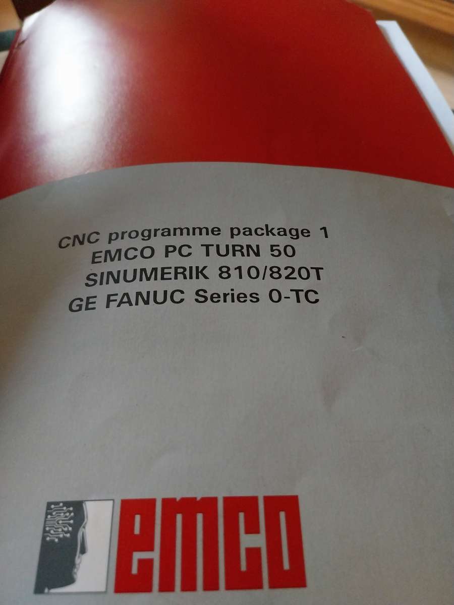
          Fanuc 0-T cover


          #683332
          Martin Connelly
          Participant
            @martinconnelly55370

            Does the controller have a USB socket for external programs? If so then external CAD/CAM apps that can write code to a file/USB would probably a useful option. For example, if you have a copy of Mach3 Turn on a PC you can use its wizards to produce code and save it to a file without needing a license for Mach3. I think Mach3 G code is based on the Fanuc G code.

            Martin C

            #683379
            Emgee
            Participant
              @emgee

              Hi Martin

              No USB the system runs from an old computer starting in DOS but does have a 3.5″ floppy drive to download from. The operating system for the lathe is WinNC and runs under Windows 95.

              I already have Mach3 and can download CAM files from Fusion with the Fanuc controller post processor, have to draw the model first though.

              ATM I write G&M codes to run an Emco Compact 5 cnc, F1 milling machine and a Denford Orac all using the original equipment and want to keep the PC50 as OEM, it appears to be hardly used and came with the original supplied tooling and inserts.

              The Fanuc program has many features that will need to be learnt so I can do my programming as needed for small parts, anything with many rads and features can be drawn in Fusion and the NC file downloaded and if I am familiar with the code can edit the program to suit my needs. Hence my desire to learn more about the Fanuc 0-T program methods.

              Emgee

              #683542
              Martin Connelly
              Participant
                @martinconnelly55370

                I think I have a spare usb floppy drive and plenty of unwanted floppies if they are of any use to you.

                Martin C

                #683803
                Emgee
                Participant
                  @emgee
                  On Martin Connelly Said:

                  I think I have a spare usb floppy drive and plenty of unwanted floppies if they are of any use to you.

                  Martin C

                  Hi Martin

                  I take it the Floppy drive is a stand alone item connected by USB, if so I certainly would find it useful, I do have a good number of floppy discs in stock and they do get reformatted from time to time for new info.

                  I will attempt to PM you with a message.

                  Emgee

                  #683866
                  Martin Connelly
                  Participant
                    @martinconnelly55370

                    Yes, stand alone powered by the USB socket. I have seen your message.

                    Martin C

                    #683883
                    mgnbuk
                    Participant
                      @mgnbuk

                      Does the controller have a USB socket for external programs?

                      Serial comms through an RS232 port – ’80s control system here !

                      To offer any meaningful suggestions I need to know how the control is configured. A “basic” Fanuc control is just that – very basic ! But they offered a very large extra cost options selection and the options chosen can vary how the control functions considerably. The manuals do not help here, as they describe the operation of all the options available and may not be applicable to your particular machine if the option is not installed. There was a Fanuc “Descriptions” manual that detailed all the functions & showed what was standard in the basic control and what was optional. Options costs varied considerably, from around £10 for simple changes like display of a clock on the CRT or resettable parts counter (incremented by the M30 end of program code for keeping track of batch sizes) to many hundreds for memory increases – a basic configuration came with only 10 metres paper tape equivalent memory. Some options were just turning on software functions, but others required hardware changes – memory increases above a certain size required extra RAM & graphic simulation required a different display board, for example.

                      In your documentation there should be a Fanuc data sheet which gives the options installed at time of purchase & which would be updated by a Fanuc technician if options were subsequently purchased – option upgrades could only be installed via an on-site visit by a Fanuc tech & they would not proceed if the data sheet was not present. The data sheet is typically a flimsy 3 sheet fan-fold dot matrix printed multi part print out with a blue type (like a carbon copy). The first page has the control serial number, build date etc. then details of the part numbers and revisions of the boards used in the system. Next was details of pcb link or DIP switch settings, then a description (with part numbers) of the installed options . Last page was a listing of the option parameter settings – these are the 9000 series parameters, each being in 8 bit binary format. These parameters are not listed in the control documentation, being “secret” to Fanuc. Any subsequently purchased option upgardes were manuall written up on the data sheet by the Fanuc tech at time of installation.

                      The Emco documentation may also list the options that Emco selected as their “standard” supply – the company I used to work for always included several options that my then-MD felt were a basic requirement for a user friendly system.

                      Do you know when the memory backup batteries were last changed ? There should be a black battery box with a Fanuc logo on the side of the electrical cabinet holding 3 x alkaline D cells. Usuallly a “BAT” message comes up on the bottom of the display (along with an expanded message on the “Alarms” page) when the batteries are depleted, but I always changed them annually before the Xmas shutdown at work, as batteries on the point of being depleted would often dip too low if left for a couple of weeks in low temperatures, leading to loss of the battery retained data. Note that with these controls the batteries must only be replaced with the system powered up – there is no “Super Cap” or other temporary memory support to enable the batteries to be changed with power off. Pull the batteries with the power off and you will loose (as a miniumum) part programs, tool offsets and parameters – not the  end of the world if you have backups, but a PITA non the less.

                      Nigel B.

                      #683979
                      Emgee
                      Participant
                        @emgee

                        Nigel

                        I have read sometimes Disks and paperwork relevant to the machine is left in the control cabinet so will remove the back cover and check.

                        I will also look into replacing the batteries as suggested although offsets etc are still retained in memory.

                        Communication is 485 via port to the ISA board on the computer, hence the need for a PS1/2 mainboard.

                        I will try and seek more info for you on what is available with the system but have noticed part counting system is in place and working.

                        Emgee

                        Just noticed the background screen behind text is pale blue, is this a mod to the system or just to indicate the reply can still be edited ?

                        #684271
                        Emgee
                        Participant
                          @emgee

                          Hi Nigel

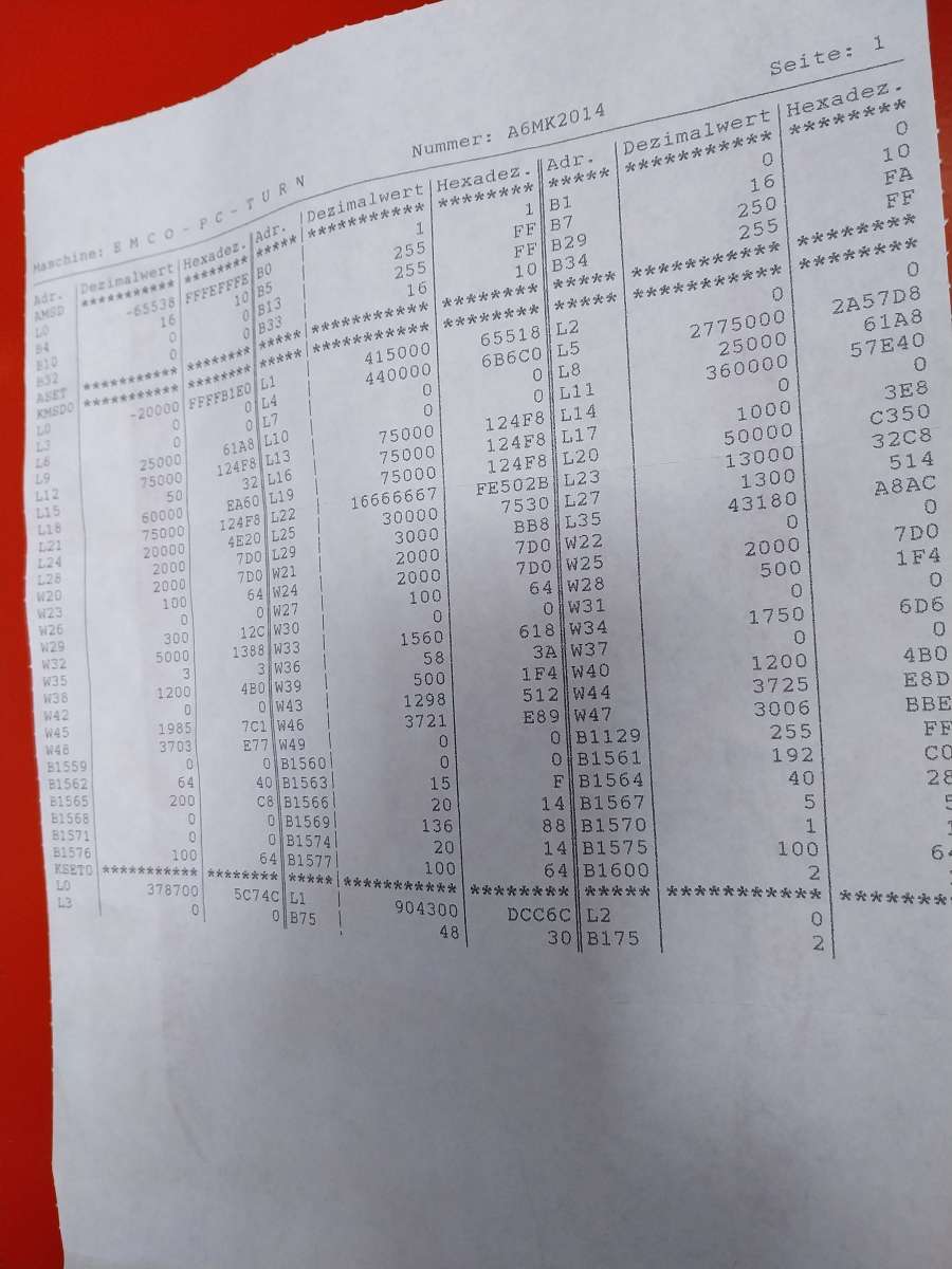
                          Picture of the info page glued inside the back cover, guess they are the settings you refer to.

                          The only black box has the Emergency stop fitted on the top so the batteries could be inside, need to remove the cover to check.

                          Machine settings PC50


                          #686014
                          Emgee
                          Participant
                            @emgee

                            No sign of any batteries inside or out of the control cabinet, seems the method of info retention has changed, asked 2 other owners of the same lathe and they have never replaced any batteries but no problems with offsets in memory.

                            Emgee

                            #686018
                            Michael Gilligan
                            Participant
                              @michaelgilligan61133

                              On Emgee Said:


                              Just noticed the background screen behind text is pale blue, is this a mod to the system or just to indicate the reply can still be edited ?

                              Alternate posts are shaded

                              … in a refreshing nod to Ergonomics

                              MichaelG.

                              #686312
                              mgnbuk
                              Participant
                                @mgnbuk

                                Hi Emgee,

                                Sorry for the tardy response – I failed to see your reply.

                                In a nutshell I don’t think you have a Fanuc control – you appear to have an Emco control that can emulate either a Fanuc 0T-C or a Sinumerik 810/820T in terms of operation.

                                Why do I think that ? The data sheet is not a Fanuc item & every Fanuc control, I have worked with (I installled my first in 1984 & have worked on older models) has battery backed memory. New controls from the factory had the battery box mounted in a temporary cardboard box attached to the motherboard to maintain the factory parameter settings during shipping – the box had to be carefully manipulated into the cabinet cutout after the control was installed without disturbing the connection or the settings were lost.

                                As a cross-check could you say what the axis servo motors look like ? If the control is a Fanuc 0T-C it will have brushless AC motors with black bodies, octagonal section, with a red end cap covering the feedback encoder. The C variant of the 0 control had a propriatatry digital interface & only their own drives could be used. Feedback was via TTL encoders – on a small lathe usually the encoder built in to the motor. If your machine has stepper motors it cannot be a Fanuc 0 control – there was no open loop, stepper motor option with those controls..

                                In some ways that would not be a suprise – a Fanuc or Siemens industrial control & drives is an expensive package, but a propriatary control on a training machine would not be great for sales to colleges etc. So having a less expensive open loop propriatary control that could emulate the operation of popular industrial controls would be advantageous.

                                So the Emco documentation should be the first stop to determine what the configuration of Fanuc 0T-C is that they have based their emulation on.

                                Nigel B.

                                #686320
                                Emgee
                                Participant
                                  @emgee
                                  On mgnbuk Said:

                                  Hi Emgee,

                                  Sorry for the tardy response – I failed to see your reply.

                                  In a nutshell I don’t think you have a Fanuc control – you appear to have an Emco control that can emulate either a Fanuc 0T-C or a Sinumerik 810/820T in terms of operation.


                                  So the Emco documentation should be the first stop to determine what the configuration of Fanuc 0T-C is that they have based their emulation on.

                                  Nigel B.

                                  Hi Nigel

                                  Thanks for your reply, I agree the statement entirely, the difficulty is not knowing exactly which version of Fanuc the machine can work with, there are AB&C + other variants of lettering after the 0T, the Emco manual states Fanuc 0-TC

                                  Have been trying different threading G codes from the Fanuc website but not found one that works without fault or doesn’t get rejected by the machine, this may just be a syntax issue though.

                                  I am in contact with a user of the same lathe model who is checking his programs for more detail of codes he uses for various cyclic functions, he will mail me copies of programs including the codes in regular use.

                                  In the meantime I will keep trying various syntax entries to arrive at something that works, ATM I run these trials well away from the chuck and only air cutting.

                                  Emgee


                                  #686339
                                  mgnbuk
                                  Participant
                                    @mgnbuk

                                    Hi Emgee,

                                    I would not get too hung up on the A, B, C thing – they all programmed much the same in terms of syntax IIRC.

                                    The differences were mainly hardware – the A version used an analogue interface to connect to the drives (+/- 0-10V), where the B and C used the digital interface I mentioned earlier. IIRC the main difference between B and C was the B was 16 bit & the C was 32 bit. The extra processing power of the C allowed (amongst other things) dynamic display of the built-in PLC ladder diagram, which simplified fault findiing enormously. IIRC they could also handle more axes. We used to use A controls for straightforward control retrofits where the original analogue drives were being retained, but used the B or C controls when doing full rebuilds were the servos were being replaced as well.

                                    IIRC the basic threading function on controls without the Multi-repetitive cycles options was using G33 for each threading pass, the “box cycle” of approach to start position , threading pass , retract & return to start point having to be written manually for each pass. I had some customers (oil tool industry “special” threads) who used this method exclusively to have complete control over the dpth of cut on each pass

                                    The G78 multi-pass threading cycle made life easier, but I have a vague recollection that one (or more) of the G78 parameters had to be entered in “least imput increment” manner (i.e in microns, without a decimal point).

                                    Nigel B


                                    #686407
                                    mgnbuk
                                    Participant
                                      @mgnbuk

                                      Emgee,

                                      Further to the above I have been having a hunt for 0-T programming examples & came across this training aid

                                      This is a Daewoo production aimed at their machines, but appears to have more accessible descriptions of the screwcutting cycles, with a worked example. This does mention that the P and Q values are to be entered without a decimal point.

                                      HTH

                                      Nigel B.

                                      #687449
                                      Emgee
                                      Participant
                                        @emgee

                                        Hi Nigel

                                        Thanks for that link, it does indeed show the system which is listed in the Emco PC59 literature.

                                        The threading cycl is a 2 line command, the 2nd line has a greater number of characters than my WinNC program will accept, mainly caused by dimensions having to be entered in microns in 2 of the functions.

                                        I need to look into modifying the software to accept the higher number of characters, help with this will be needed from some kind soul.

                                        Still trying with the other cyclic commands to get more idea of what the lathe can do, I don’t give up easily !!!

                                        Emgee


                                        #689754
                                        Emgee
                                        Participant
                                          @emgee

                                          Update for those interested, I have found that when the command line overfows I can go into the line and using the edit command add further characters into the line so completing all info required for the command to function.
                                          The turning and facing cycle command line/s for the Emco Compact 5cnc are so much simpler to enter and carry out the same function with just 5 parameters.

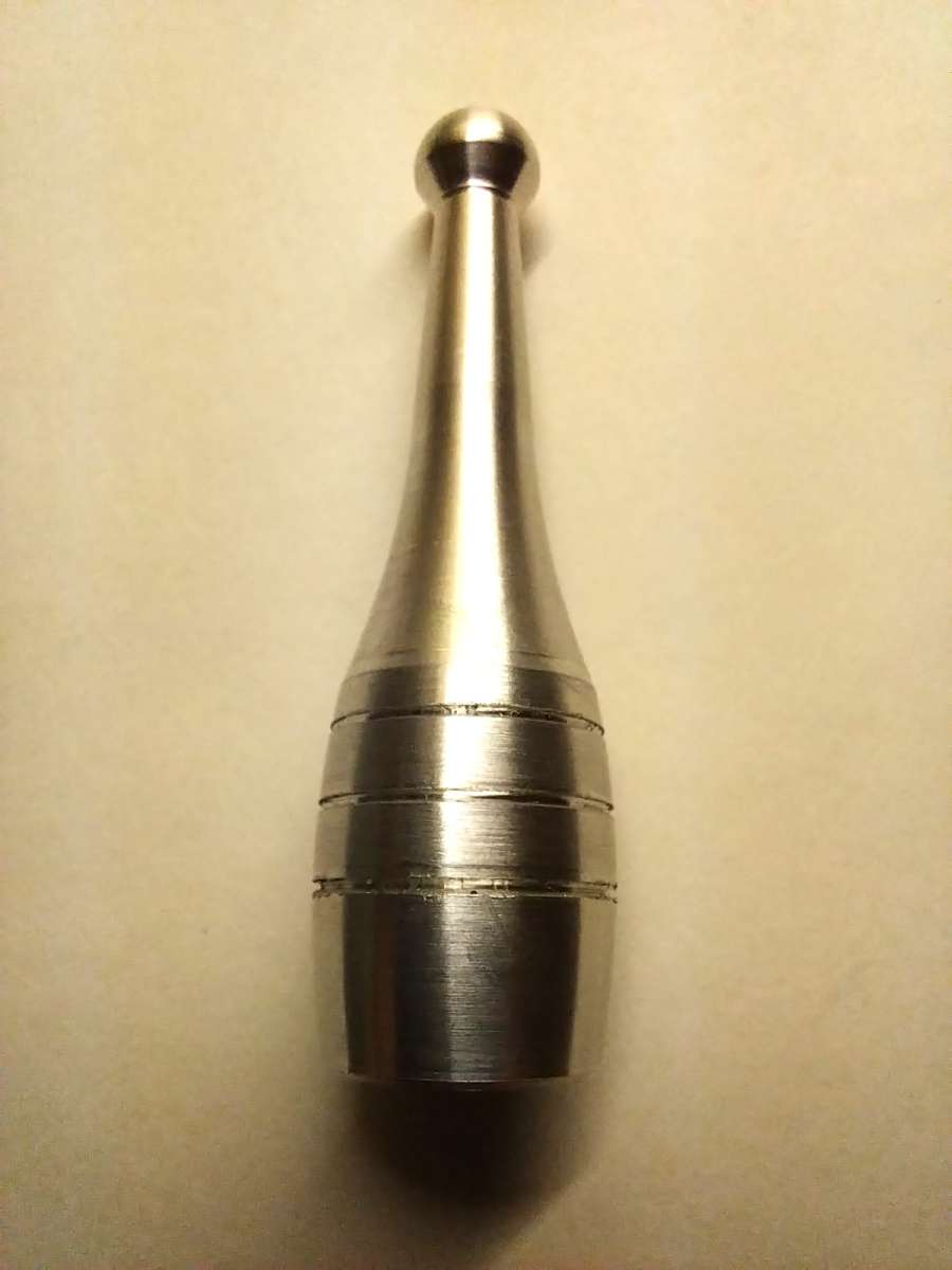
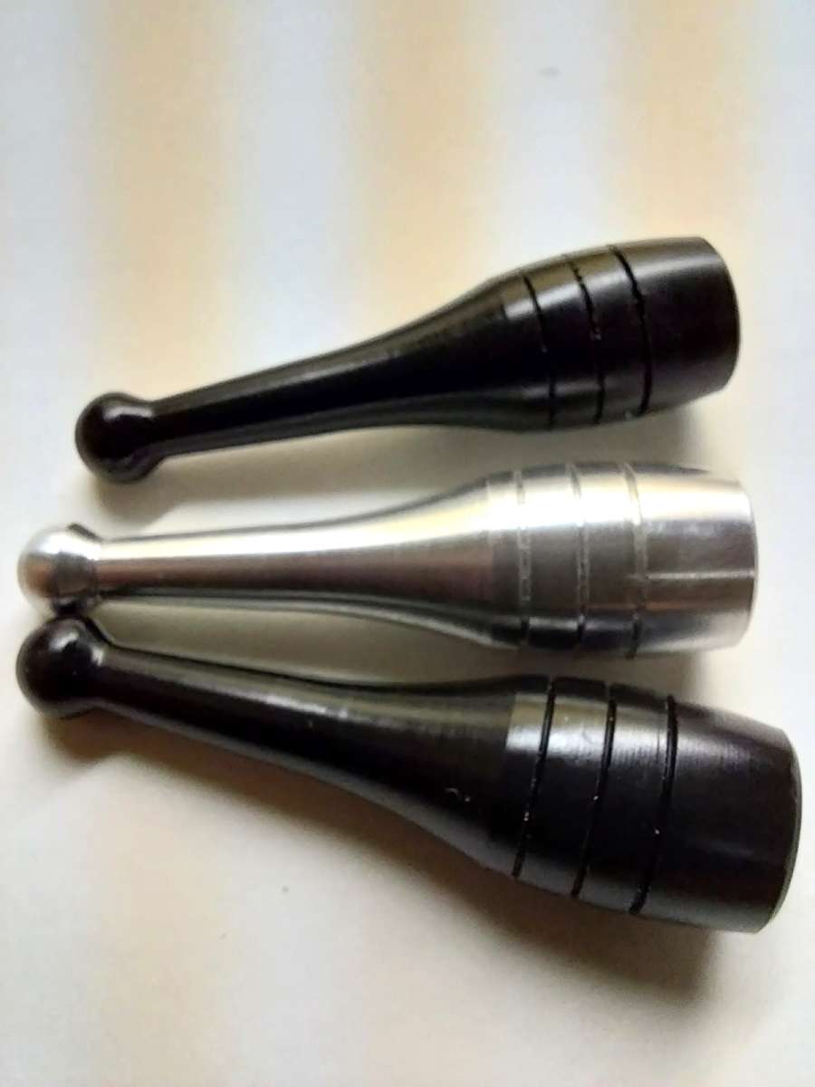
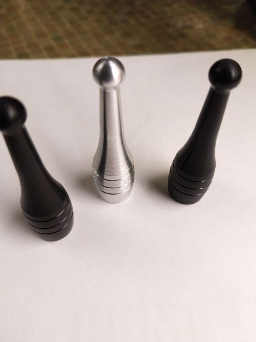
                                          After getting the tool offsets sorted I loaded an example program from the Emco program manual to turn a Bowling pin, these came out OK after adjusting spindle speed and feedrates for turning and parting.

                                          Still a huge amount to take on board but progressing slowly.

                                          Emgee

                                          Bowling pin 3Bowling pin 2Bowling pin 1

                                          #702278
                                          Emgee
                                          Participant
                                            @emgee

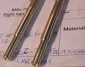
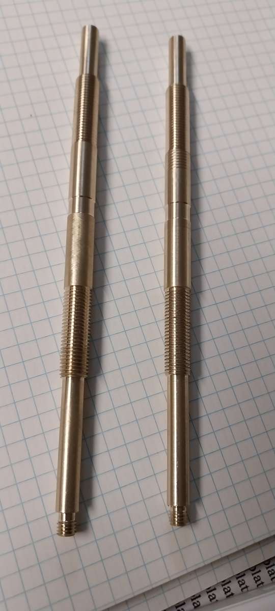
                                            Got a turn and thread program running to do some brass parts so all is not lost but still having some programming problems with G72 turning cycle.

                                            2 shafts 23.12.2320231223_161107

                                          Viewing 20 posts - 1 through 20 (of 20 total)
                                          • Please log in to reply to this topic. Registering is free and easy using the links on the menu at the top of this page.

                                          Advert

                                          Latest Replies

                                          Viewing 25 topics - 1 through 25 (of 25 total)
                                          Viewing 25 topics - 1 through 25 (of 25 total)

                                          View full reply list.

                                          Advert

                                          Newsletter Sign-up