I’m surprised that EMCO use 3-phase motors only, supplying 3-phase fitted for Steinmetz to single-phase customers; it’s possible though!
Some photos of a circuit diagram, or the motor and the inside of its terminal box would reveal what Ian has. If it is Steinmetz, far from ideal because the compromise limits the motor to a maximum of 70% power and 25% torque at best. Much worse if the capacitor isn’t in tip-top condition, and ye olde capacitors rarely are. If the EMCO really has a 3-phase motor, and the capacitor is dud, it’s a good time to consider a VFD, which would enable the motor to deliver full power and torque, plus speed control.
Unlikely to be a voltage thing. I find the difference between 440V and 230V 3-phase confusing, so I’m sticking my head over the parapet with what follows. Happy to be put right if my simplification is wrong or confused.
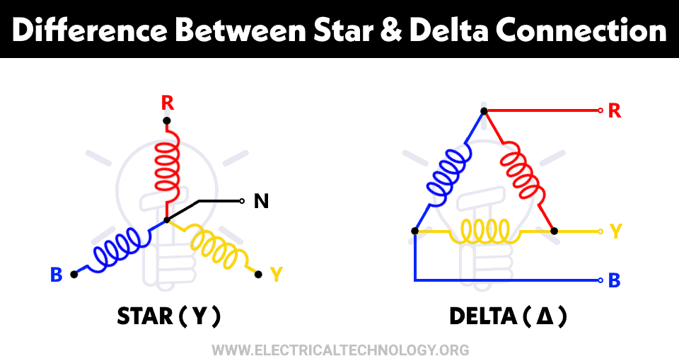
A 3-phase motor contains 3 windings, that can be connected in either of two configurations: star or delta.

Thus the same motor runs on either 440V (windings connected in a star), or 230V (windings connected delta). There are a bunch of pros and cons that decide if a motor is best connected star versus delta in a particular application, but power isn’t one of them: both configurations deliver the same power output.
A good reason for wiring delta is that single-phase to 3-phase converters of all types only have to output the same voltage as the single phase input. Not having to boost mains voltage from 230V to 440V reduces cost and complexity whilst increasing reliability and safety. (The cheapest way of producing 440V 3-phase if the need can’t be avoided is with a VFD, mainly because they don’t need a big transformer. 440V-out VFDs took a while to become affordable but a good option if one happens to buy a classic machine with a star only motor.)
Industry play to different rules, and star-wound motors often suit their purposes better than delta. Consequently, although many motors bring out all six winding ends to separate terminals, many others hardwire the windings to a star point inside the motor, providing ony 4 terminals in the box – three for the phase inputs, plus neutral.
Star only motors can often be converted to delta by opening the motor, finding and breaking the star point, and adding wires to bring out all 6 winding ends to the terminal box, where they can be connected delta. Difficulty of modifying an internal star point varies between easy-peasy and impossible, depending on where the manufacture chose to put the star point. Often suits them to connect the star point very obviously at one end of the stator with easy access to all the wires, unfortunately burying it deep inside the motor is also common. Sadly, manufacturers have absolutely no consideration for amateurs wishing to adapt their products!
In theory adapting a star only motor to delta is a bit risky because the manufacturer might have taken advantage of a star motor needing less copper and insulation compared with delta. In practice unlikely to be a problem for amateur use. Industrial motors are built to take a beating and hobby work is genteel! Plus it’s been several decades since different grades of magnet wire were used to save money, at least in the size of motor a hobbyist is running (less than 7kW).
If a motor plate can’t be found, the terminals inside Ian’s motor box should reveal if it’s 3-phase with a choice between star/delta. That informs what Ian might do next.
Faulty capacitor apart Ian’s EMCO motor not getting warm may be because it’s a well-made continuously rated motor. We need to see the missing motor plate! As the cost of a motor of given output is dramatically reduced when it only has to meet a reduced duty cycle, it’s unusual to find continuous rated motors fitted unless necessary. This is one of the big differences between hobby and industrial kit, because industrial kit was built to work hard round the clock on a shift system, whereas hobbyists are unlikely to work anything like that hard. Beware driving hobby machines heavily or for extended periods: overstressing the mechanicals and not allowing the motor and electronics time to cool down risks magic smoke and breakages!
Perhaps Ian is operating well within the capacity of his machine. Motors and bearings that get hot quickly worry me far more than cool ones! On the other hand, maybe the motor isn’t performing. What’s needed is some form of dynamometer to measure the power actually available at the spindle: an interesting project if I had time and was feeling better!.
Whilst ancient capacitors are on the table, there’s an argument in favour of replacing them on suspicion alone because they are difficult to test properly.
- They often leak current, but most ohmmeters don’t apply enough voltage to detect this, not even a trusty 27V AVO. The needle flicks as if the capacitor were storing charge correctly, but it isn’t! Worse, although the flick is encouraging an ohmmeter can’t measure the capacitance to confirm the capacitor is within its original ratings.
- Many capacitance meters operate by measuring how long it takes to charge the capacitor, which works well most of the time. Unless the capacitor is DC leaky, in which case the meter is confused. Common to measure elderly capacitors and find the meter believes they are well above the original specification, with a 20uF unit reading 30 or 40uF. Unfortunately not because the capacitors of yesteryear and improve with age like fine wine, it’s because they go bad in a way that bemuses a mid-range meter. Instruments that aren’t fooled are outside my budget.
Dave
duncan webster 1.


