Emco FB2 Quirks and Additions

Advert

Emco FB2 Quirks and Additions

Home Forums Manual machine tools Emco FB2 Quirks and Additions

Viewing 9 posts - 76 through 84 (of 84 total)
  • Author
    Posts
  • #550597
    Graham Meek
    Participant
      @grahammeek88282

      Thanks Neil for adding the PDF's

      Regards

      Gray,

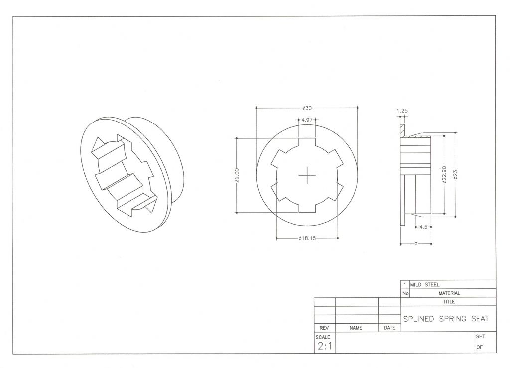
      splined spring seat.jpg

      There is one Quirk that has plagued me with the FB2 over the past 35 years or so. That is a growling noise in the 1100 RPM range. I must add that my machines have always been Single phase, so I cannot say if this happens on the 3 Phase machines.

      One machine I had early on would also exhibit this characteristic in the 680 RPM range. In all cases the noise would disappear as soon as some cutting forces were present, only to reappear when the machine was running light. I have postulated an umpteen theories over the years as to why this happens. None of the remedial fixes tried for each theory, had no or little effect. On one machine the growl would only start when the machine was warm. My current machine would growl what ever the temperature of the machine, or the workshop.

      Changing the viscosity of the oil and the oil type, have had little or no effect. A recent overhaul showed the Sliding Gear, (Part No E3A 010 060) and the Gear Bank (Part No E3A 010 070) had signs of wear due to the misalignment of the selector arm. All of the other gears were in perfect condition. Even showing signs of the original grinding marks on the gear form. Replacement gears made no effect to the growl once the machine was reassembled.

      A couple of weeks ago at long last the Penny finally dropped. The FB2 uses a Helical spring around the upper part of the Spindle to return the Quill. One end of the spring rests on the splined drive gear, the other rotates with the spindle via a spring seat on the spindle. There is some play between the splines but as my machine parts are with-in drawing limits it cannot be from wear.

      What I believe is happening is that the spring being a torsional member is allowing the spindle to oscillate on the splines due to the design clearances. When the spindle is loaded the clearance is taken up. I also believe the Cyclic nature of the Single phase motor adds to this, in the 1100 range.

      Having postulated one more theory I thought I would add the splined spring seat above to the spindle. The splines on this seat are a nice sliding fit over the spindle splines but with hardly any play. The machine has been used quite a lot over the past couple of weeks and so far there has been no growl. If anything the machine seems quieter throughout the range, but I may be suffering the placebo effect on that one. One can hear a cyclic variation in the tone of the machine which could not be heard before in the 1100 range.

      Regards

      Gray,

      Advert
      #552571
      Graham Meek
      Participant
        @grahammeek88282

        fb2 gear assy.jpg

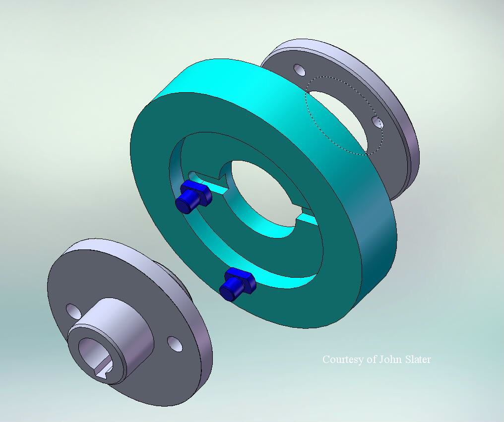
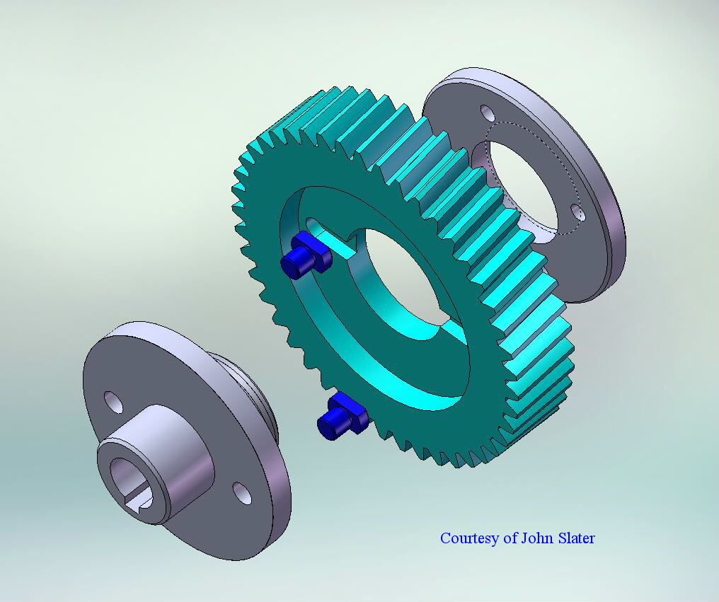
        It has been a while since I posted details about the FB2 Tufnol Gear 47. John Slater has kindly produced a 3D view of the proposed design which I am currently working on.

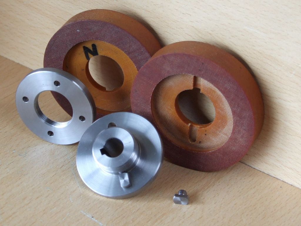
        fb2 helical gear parts.jpg

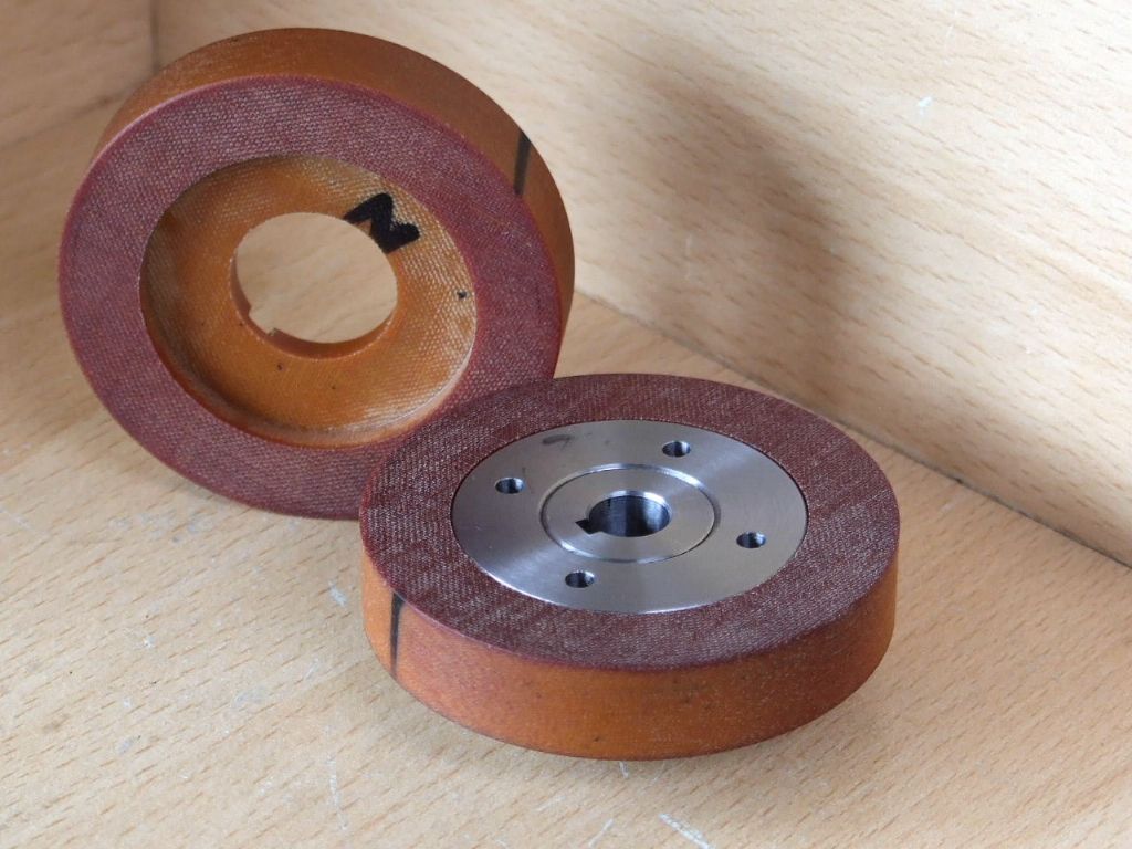
        fb 2 helical gear parts assembled.jpg

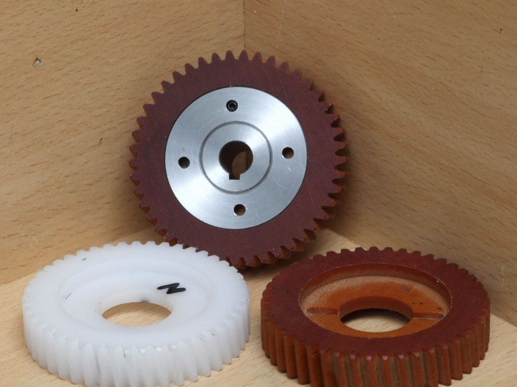
        Emco press their Tufnol gear onto the arbor over a coarse knurled diameter. The gear is retained with what I presume to be Epoxy glue from what I can see. I would expect the gear teeth are then machined after the parts are assembled.

        Trying to make the gear separate and pressing this onto a knurled arbor did nothing to inspire my confidence in maintaining any form of concentricity.

        To this end it was decided after quite some debate between John and myself to drive the gear with two face keys and retain the parts together with a Ring Nut. This type of construction lends itself to the use of other materials for the gear, such as Delrin. Which might present problems if the assembly was just glued together. Without that is resorting to some form of exotic glue. The Ring Nut will be locked on assembly by drilling an tapping M3 through one of the Peg spanner holes, (one that is not over the drive keys, hence the need for 4 spanner holes) and inserting an M3 Allen grub screw.

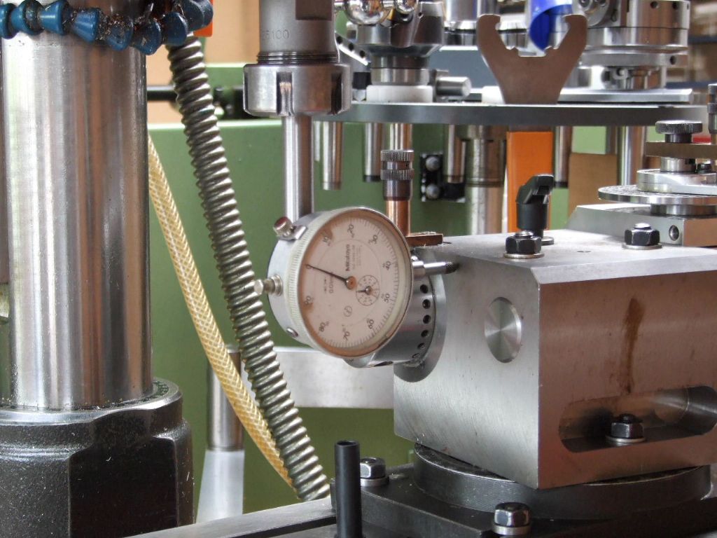
        checking the 8 degree angle setting over 30mm.jpg

        The Dividing head has been rotated through 8 degrees and the DTI is being used to check the angle over 30 mm of cross-slide travel.

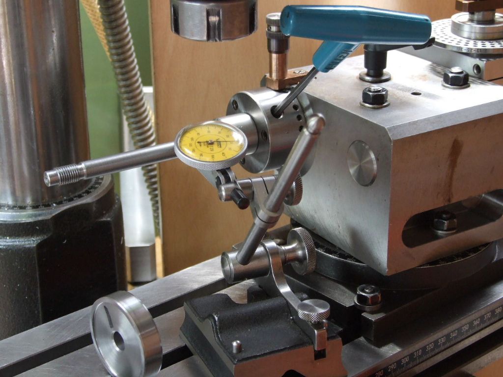
        setting concentricity of arbor, the ght way.jpg

        The Mandrel to mount the gears is next checked for concentricity and adjusted using the GHT, Versatile Dividing Head method.

        scribing lines 0.2 mm above and below centreline.jpg

        Once the gear is assembled with its black Delrin backing piece, (to stop the Tufnol delaminating during cutting of the Gear) two lines are scribed 0.2 mm above and below the centreline. Similar lines are already marked on the width of the gear blank. After which the gear blank is rotated trough 90 degrees to get the marks at TDC.

        These will be used to centralise the cutter over the blank. The cutter needs to make contact in the 0.4 mm square. Once that is, the FB2 has been configured for Horizontal work which will have to wait until tomorrow.

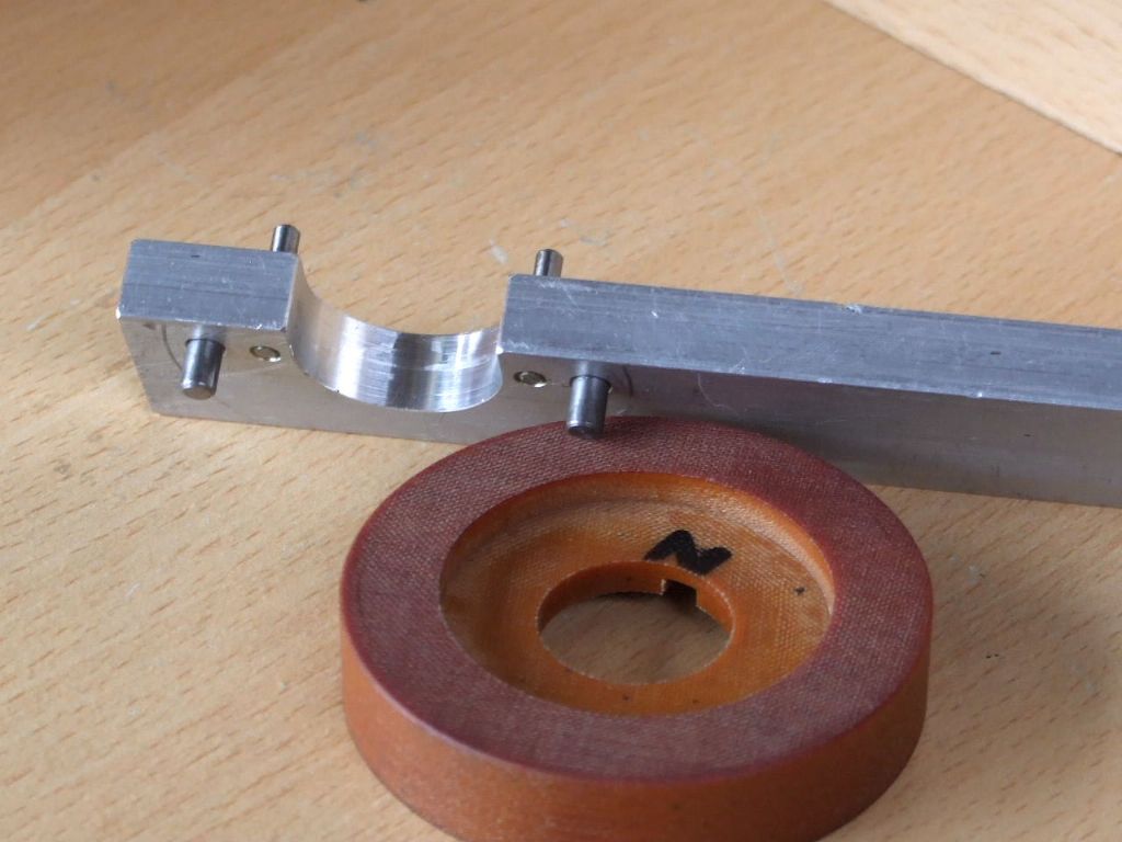
        Below is the double side Peg Spanner to fit the Gear and the FB2 Quill Assembly,

        double sided peg spanner made for fb2 quill.jpg

        Regards

        Gray,

        #552757
        Graham Meek
        Participant
          @grahammeek88282

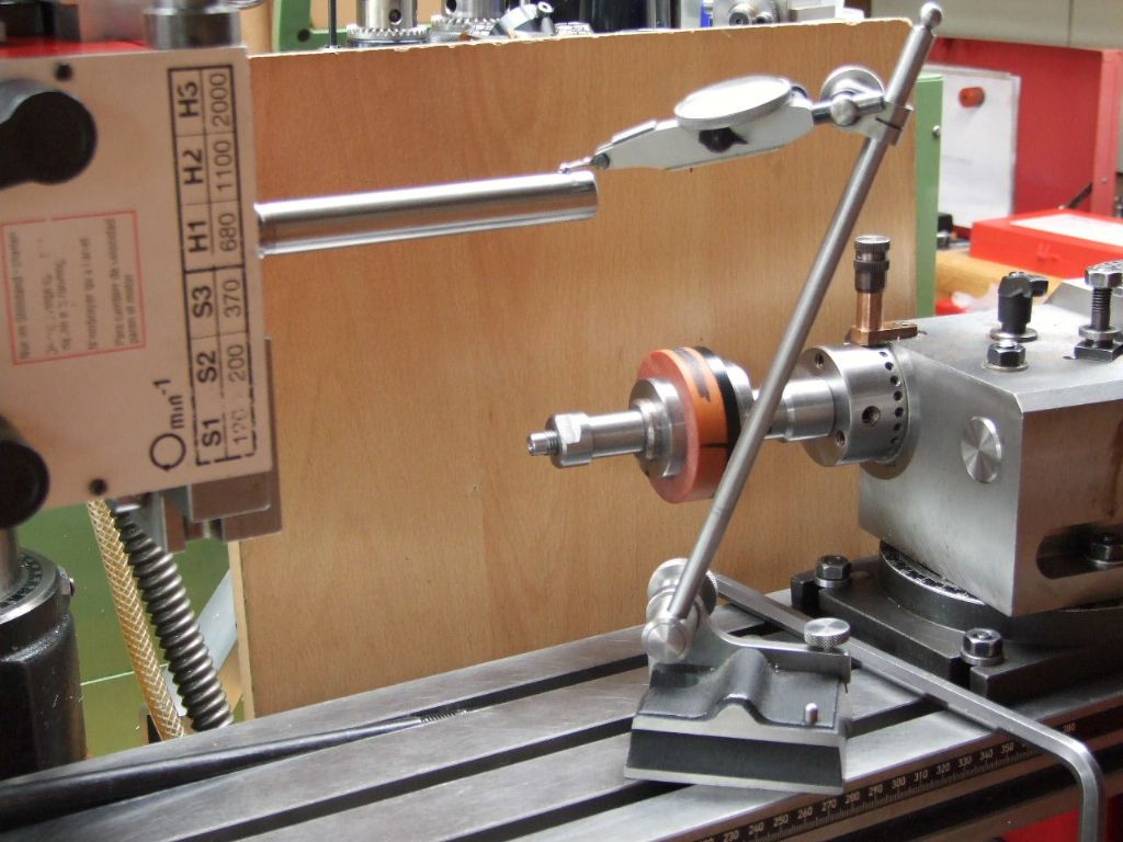
          clocking test mandrel parallel with table.jpg

          The first operation today was to clock the Test Mandrel parallel to the table.

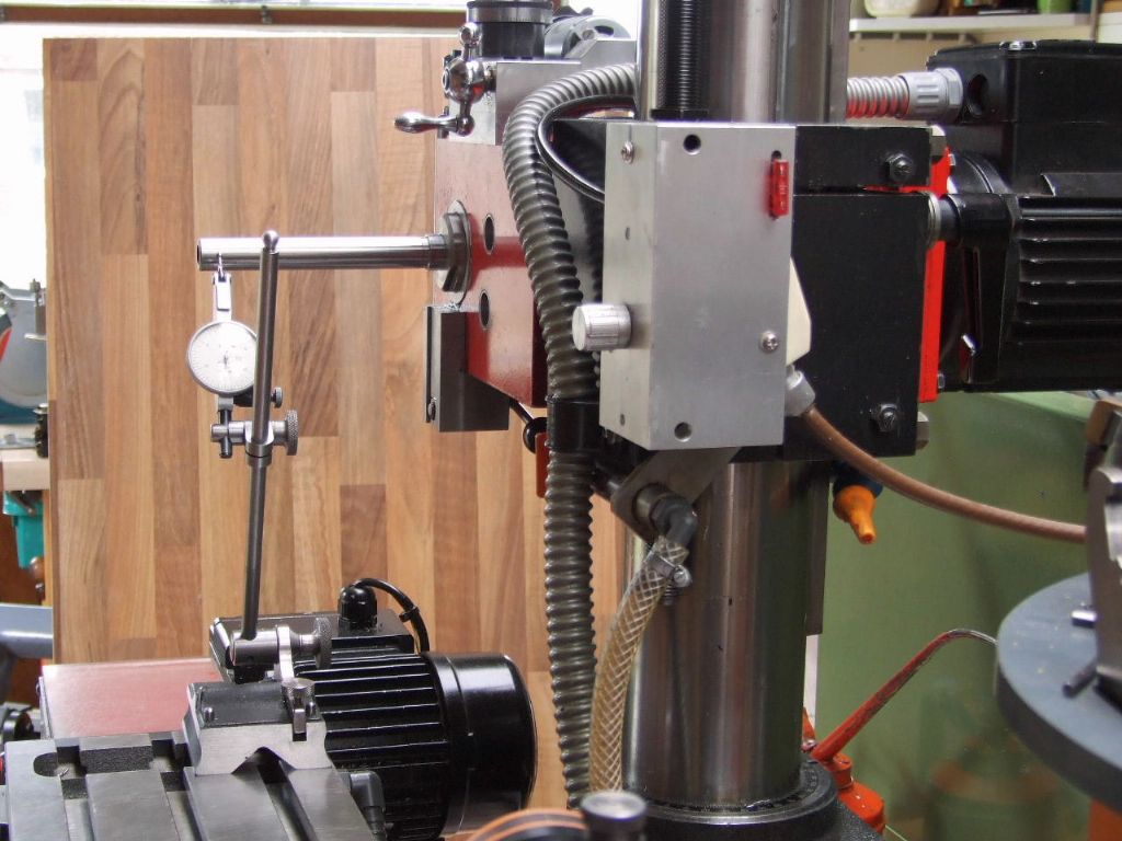
          clocking test mandrel parallel with cross-slide.jpg

          After which the Column of the milling machine is rotated through 90 degrees and the Test Mandrel clocked parallel to the Y-Axis movement. The Mandrel was again clocked over the top to ensure that it was still parallel with the table.

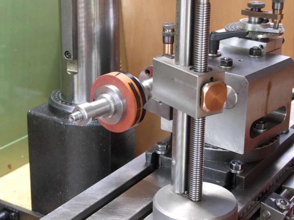
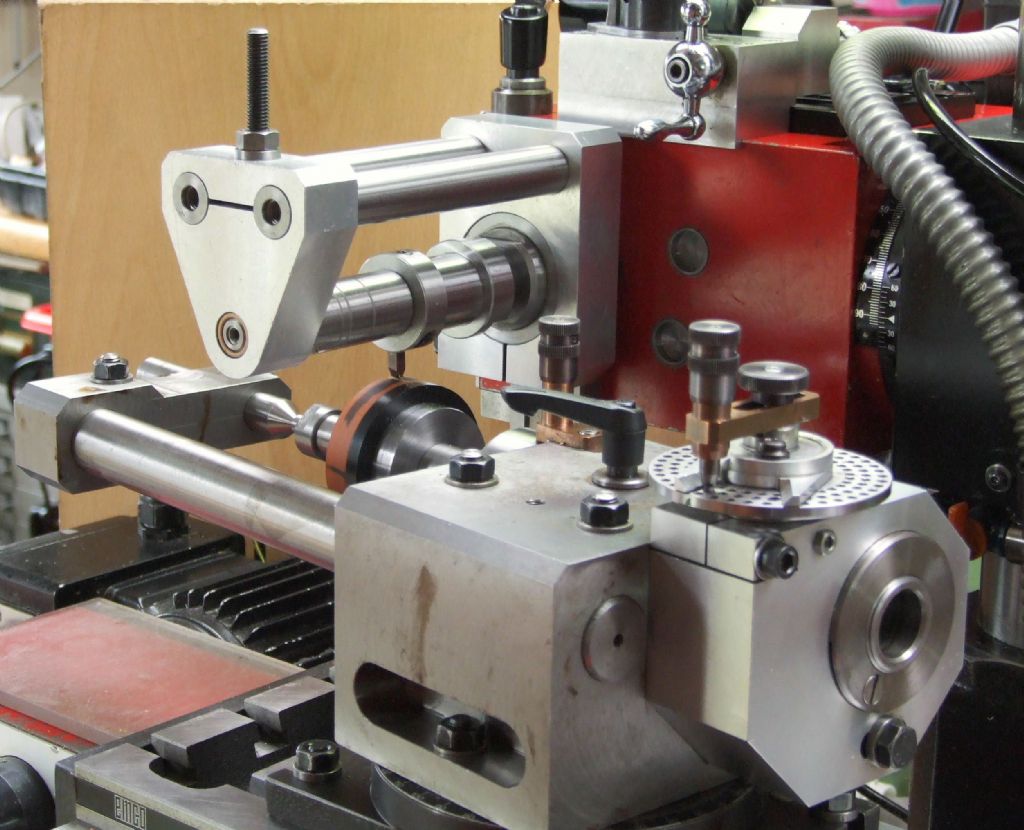
          cutter set on gear blank centrelines.jpg

          This view shows the Dividing head repositioned to the other end of the table nearest the table feed motor. The Over-arm support for the arbor has been added as well as the Centre support bar on the Dividing Head. The cutter was set using the scribed lines from yesterday and a trial cut taken to see if the cutter was equally disposed about them.

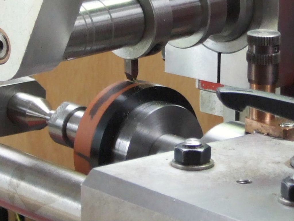
          close-up of cutter setting.jpg

          Lastly a close-up of the witness mark. Tomorrow I hope to cut the gears in earnest.

          Regards

          Gray,

          #553038
          Graham Meek
          Participant
            @grahammeek88282

            Yesterday was a good day, I managed to cut the Tufnol gears as well as some Delrin ones. When I started out to do this project I did not know I had the Delrin, so when I chanced upon a billet yesterday, I thought why not make a couple more spares.

            finished input gear with spares, note m3 grubscrew at 12 oclock.jpg

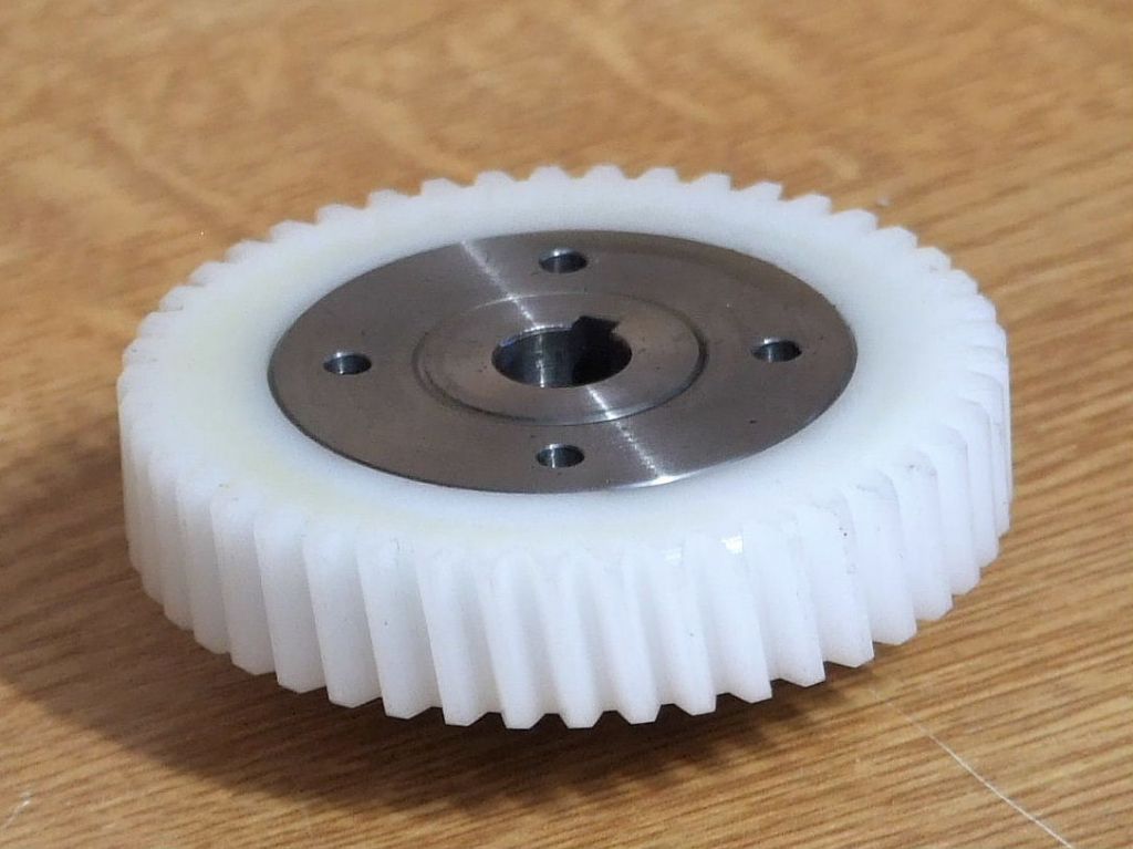
            Above is the finished assembly and some spares, note the M3 Grub screw to lock the Ring Nut at 12 o'clock. I find clicking on the photo gives a better view.

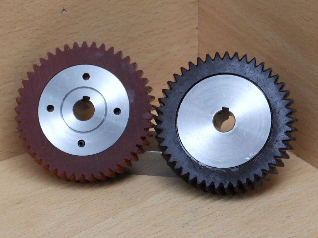
            the new spare and the original.jpg

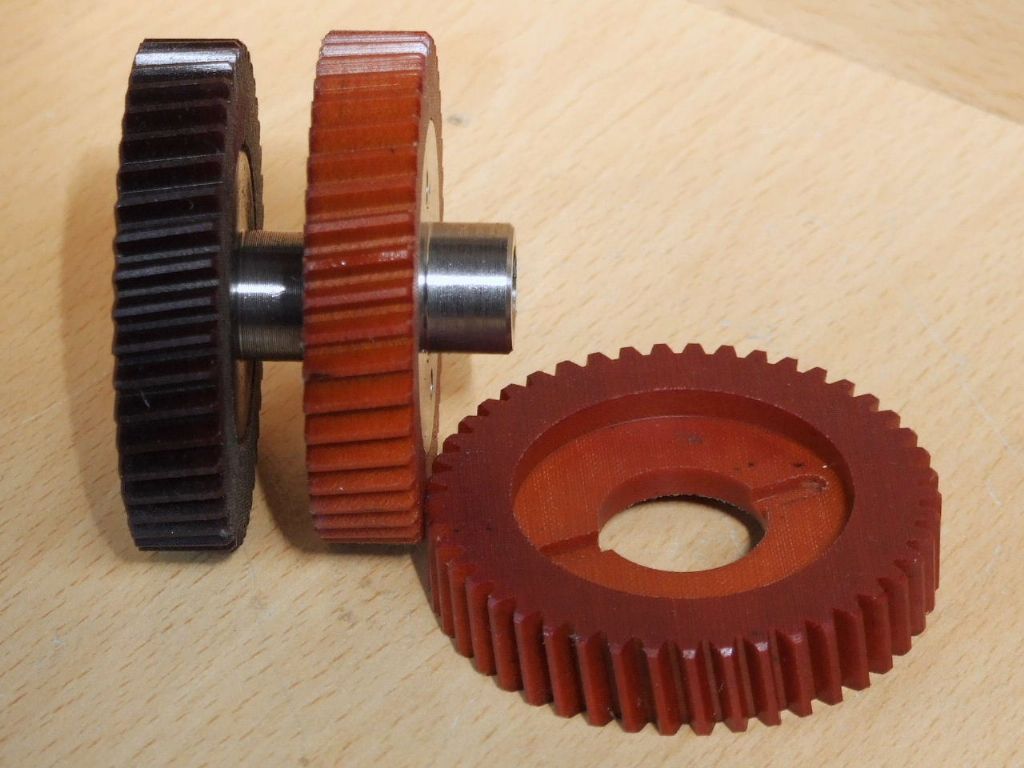
            For comparison the new Spare part on the left and the Original taken from my FB2.

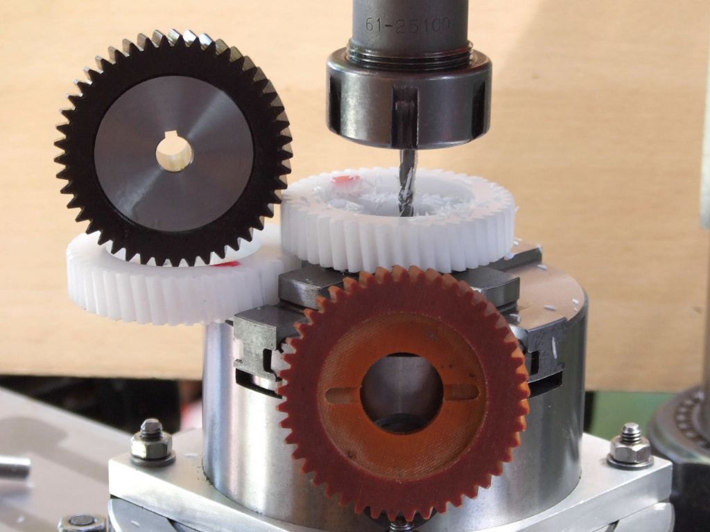
            machining the keyways in the delrin gears.jpg

            Lastly machining the Keyways in the Delrin gears. The Spare Gear assembly is driving the machine and the Emco Original. Just to show the gears work and to remove any doubt about suitability.

            While the gear produced yesterday is not a true Helical Gear, the FB2 is not grumbling about the fact. There is certainly no difference in the noise levels or the backlash between the motor gear and the Spare. If anything it may be very slightly less.

            Regards

            Gray,

            Edited By Graham Meek on 07/07/2021 13:25:18

            #553670
            Graham Meek
            Participant
              @grahammeek88282

              fb2 gear complete.jpg

              For those following this post John has added the gear teeth to the 3D view. For readers who would like further details in the form of drawings, I am currently preparing an article for MEW to be published shortly.

              Regards

              Gray,

              #563440
              Graham Meek
              Participant
                @grahammeek88282

                As promised in the article and above, I have now had chance to trial the new FB2 Tufnol gear. Having done quite a bit of heavy milling with my inserted tip 50 mm diameter Face Mill on Mild and Tool Steel. As well as the Emco 40 mm diameter HSS Face Mill. I decided it was time to take a look at how things were doing in the gearbox.

                fb2 input gear, original on the lt, new gear after about 100 hours use.jpg

                This is the condition of the new gear on the Right compared to the original on the Left. Despite the new gear not being a true Helical gear there are no signs of scuffing on the edges of the teeth. Which is where I would expect to see some.

                Currently I am running the Delrin gear, which to me seems quieter still. I have not had a chance to do any serious milling with this gear as yet, property maintenance has got in the way, but that will soon change after this week, as a new project is started.

                Regards

                Gray,

                #599648
                Graham Meek
                Participant
                  @grahammeek88282

                  As the FB2 is going shortly I thought I would share one last photograph with those who have been following the post.

                  I have given the Delrin Gear assembly an extended trial since my last post. It has had a solid 6 months machining a wide variety of materials, with different metal removal rates. The gear shows no sign of distress and if anything it was a lot quieter in use.

                  fb 2 delrin input gear.jpg

                  I hope all those who have followed this post have found it interesting and helpful.

                  Regards

                  Gray,

                  #599666
                  DiogenesII
                  Participant
                    @diogenesii

                    ..very interesting and helpful, Graham.

                    …actually seeing proof of the effectiveness of simple and straightforward 'helical' gear production (and the hubs) is a source of great hope and inspiration – it's on the 'To-Do' list..

                    A Delrin-Geared Hobbymat Milling Head Owner

                    #732642
                    Ian P
                    Participant
                      @ianp
                      On Graham Meek Said:

                      I have been asked over the years about my way of working. That is do I mark-out components then centre popping and drilling any holes from this. For me, this is going the long way around, but I will readily admit some jobs do not warrant my way of working, or are just too big or complicated to mount on the mill.

                      All my work is done by co-ordinate location, the fixed vice jaw of the machine vice being set to Zero for the Y-axis. The Vice End Stop being the X-axis Zero. This way of working has other benefits when milling a component. Knowing the size of the cutter being used I can mill any up-stand or step to size without reference to my Vernier, simply by using my dials and scales on the machine.

                      Locating the fixed jaw face is done with the following little item I made many years ago from an mild steel off-cut.

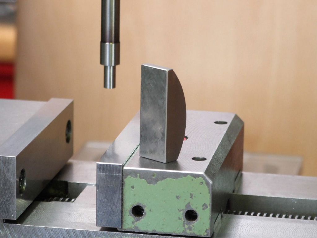
                      fig jaw locator and edge finder.jpg

                      The curved rear face of the bar stock ensures the flat face is up against the fixed jaw. A tipping moving jaw combined with a rectangular block could give a false reading. Due to the tipping moving jaw making the rectangular block cant over to towards the moving jaw.

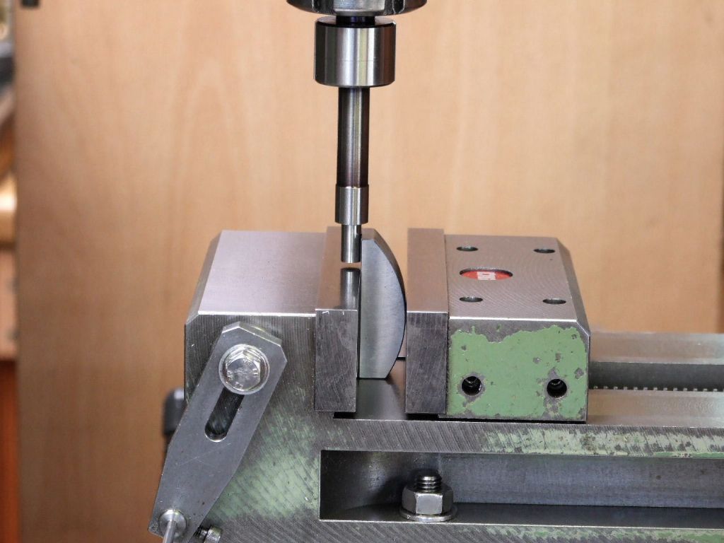
                      fig edge locator in use.jpg

                      Three for the price of one here, first the edgefinder set-up, the edge-finder is again home made.

                      Secondly the two holes in the moving vice jaw are M5 tapped holes. A Delrin plug and M5 grubscrew lock the moving jaw slide adjustment screws. The moving jaw adjustment lasts a lot longer with this modification.

                      Thirdly is my vice stop for locating similar components in the vice with reference to the X-axis. To locate longer components I have an extender stud which screws into the same location and the stop screws into this in the same way as it does the vice.

                      Under the head of the M6 hex-headed bolt is a Disc spring washer which allows the stop to be un-clamped and adjusted without fear of the stop dropping due to gravity, while I locate the M6 spanner. The disc spring also keeps swarf out from the interfaces by keeping them in contact. The 3 mm diameter silver steel rod is housed in a split bush which is retained in the stop by a circlip. The fit is extremely good and the head of the split bush is on the thrust side of the stop. The locking screw is an M4 capscrew which means the same 3 mm Allen key used to adjust the machines Quill depth stop can be used to lock the vice stop. One less item to have to locate, (had I used an M4 grubscrew this would need a 2 mm key).

                      Regards

                      Gray,

                      Apologies for waking up a four year old thread, but after coming across Gray’s excellent pictures of an edge finder in use i was curious as to what ‘resolution’ and repeatability that type of edge finder is capable of?

                      Secondly, what is the advantage of referencing off a face that is ‘transferred’ off the face that matters?

                      Ian P

                    Viewing 9 posts - 76 through 84 (of 84 total)
                    • Please log in to reply to this topic. Registering is free and easy using the links on the menu at the top of this page.

                    Advert

                    Latest Replies

                    Home Forums Manual machine tools Topics

                    Viewing 25 topics - 1 through 25 (of 25 total)
                    Viewing 25 topics - 1 through 25 (of 25 total)

                    View full reply list.

                    Advert

                    Newsletter Sign-up