To:
Kiwi Bloke, Nigel B, Jim, and Graham.
Thank you for all the suggestions and advice. I spent the day yesterday working on this and used a combination of suggestions and test methods and now have the mill nicely within acceptable tram limits.
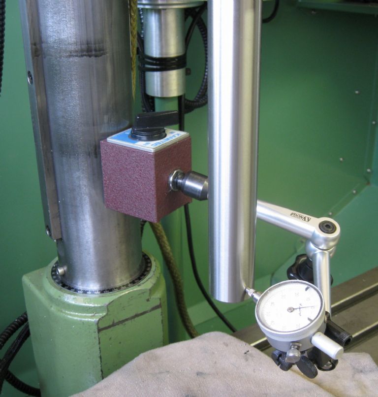
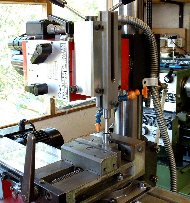
I first worked on setting the 'nod' on the head assembly – I used an MT2 Test bar as suggested by Graham – Set in the spindle. the test bar parallel section is 250mm long, runout in the spindle , at the spindle end of the bar is barely evident on the DTI. At the end of the bar, furthest from the spindle, runout is half a division on the 0.01mm DTI. I set the DTI base on the column, with the DTI tip on the bottom of the test bar in North South pose, ie, to check parallelism between column and test bar when running the head up and down.
North South Nod

This resulted in a half circle shim 0.008mm ( as close as I can read..) inserted in the lower hemisphere between the column sliding casting and the mill head casting. The shim extends to within 20mm of each bolt ( one left, one right) fastening the rotational mode. Ideally I should remove the head from the column casting and scrape it in, but that is a big job – remove, scrape, fit and repeat…The head is HEAVY!
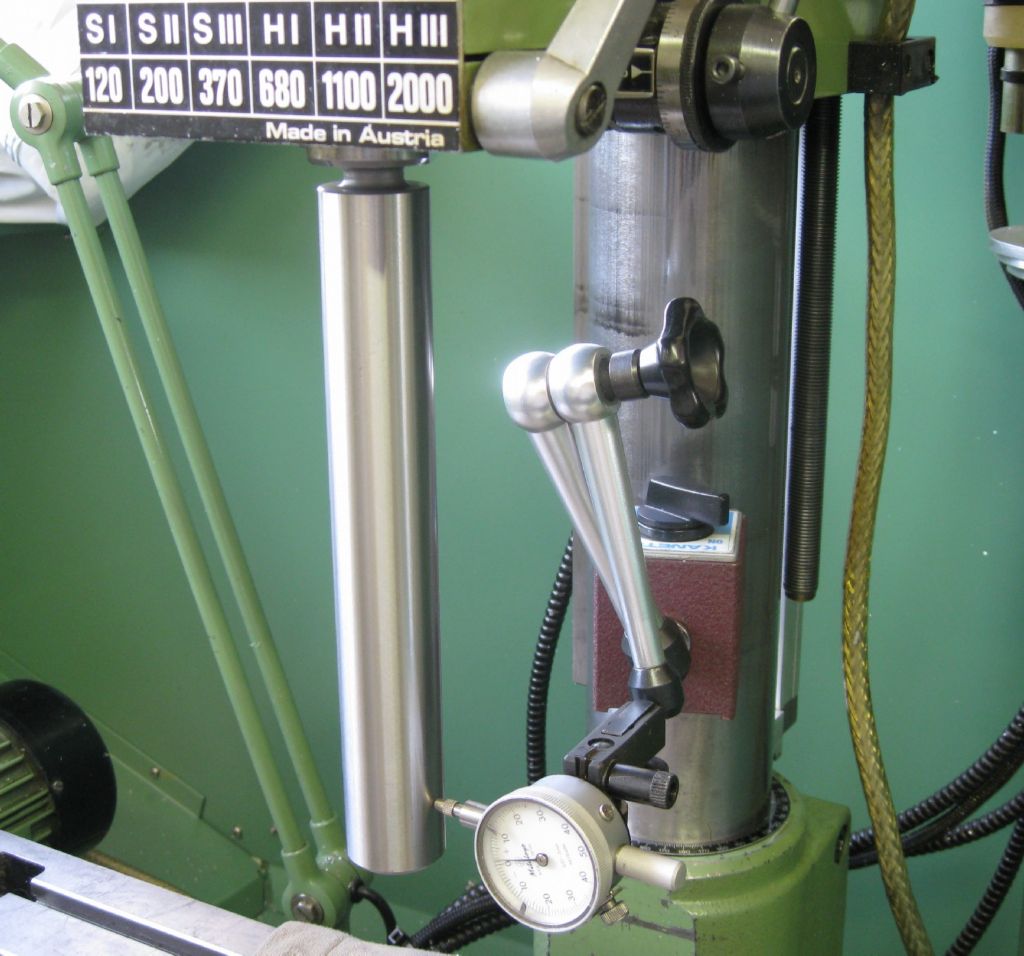
Next. move the DTO to the set East_West roll of the head, relative to the column.
East-West Roll

The two head-roll bolts were then loosened and the head tapped into vertical, bolts fastened, re-tested, etc.
The DTO was then moved back to the North_South position and nod re-checked. This since if either nod or roll are out, the DTI tip will not ride down the true axis of the test bar, but slip over the edge on the circle., so to say, with a false DTI reading. This was checked and redone a few times, till nod and roll, wrt the column, was less than a third of a DTI division or so over the 250mm test bar length. ( 1 div = 0.01mm)
For reference, the head was locked on the column, and the DTI set to midway on the test bar height, set in nod mode position. The quill was then fed down to its limit, with the DTI registering no discernable deviation.
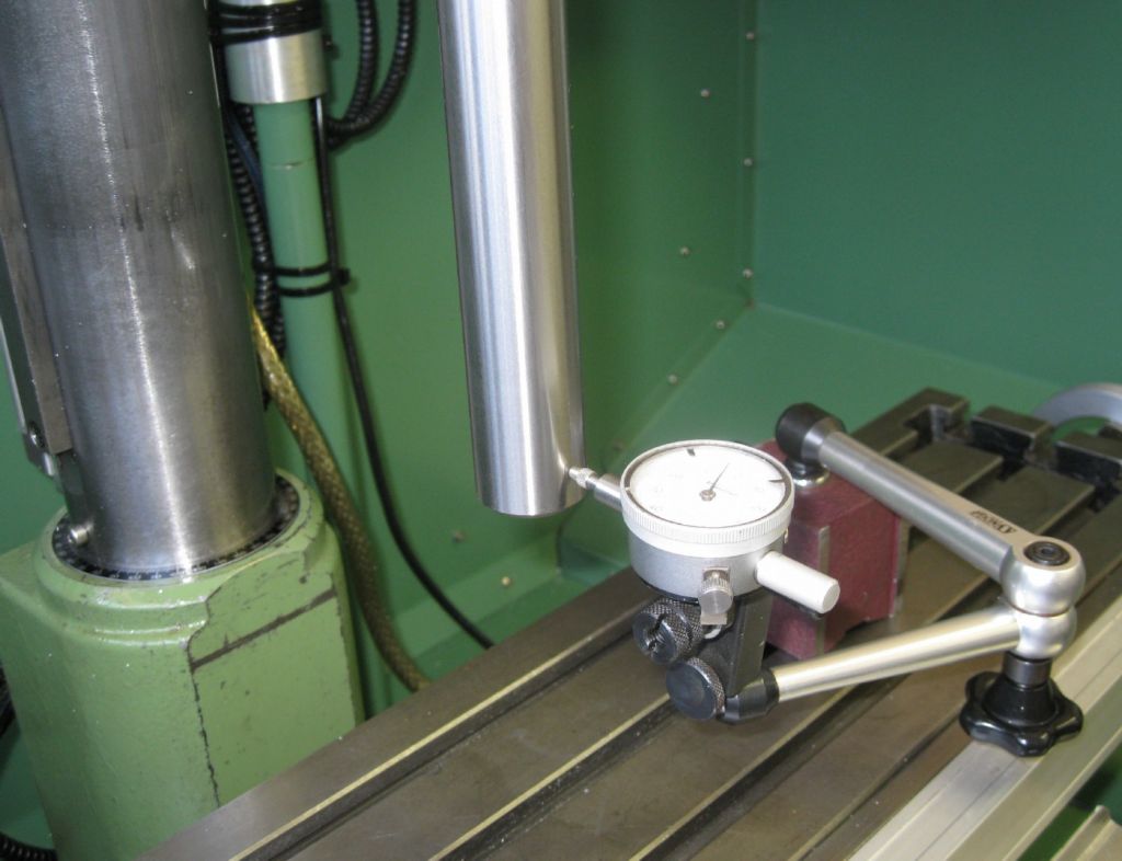
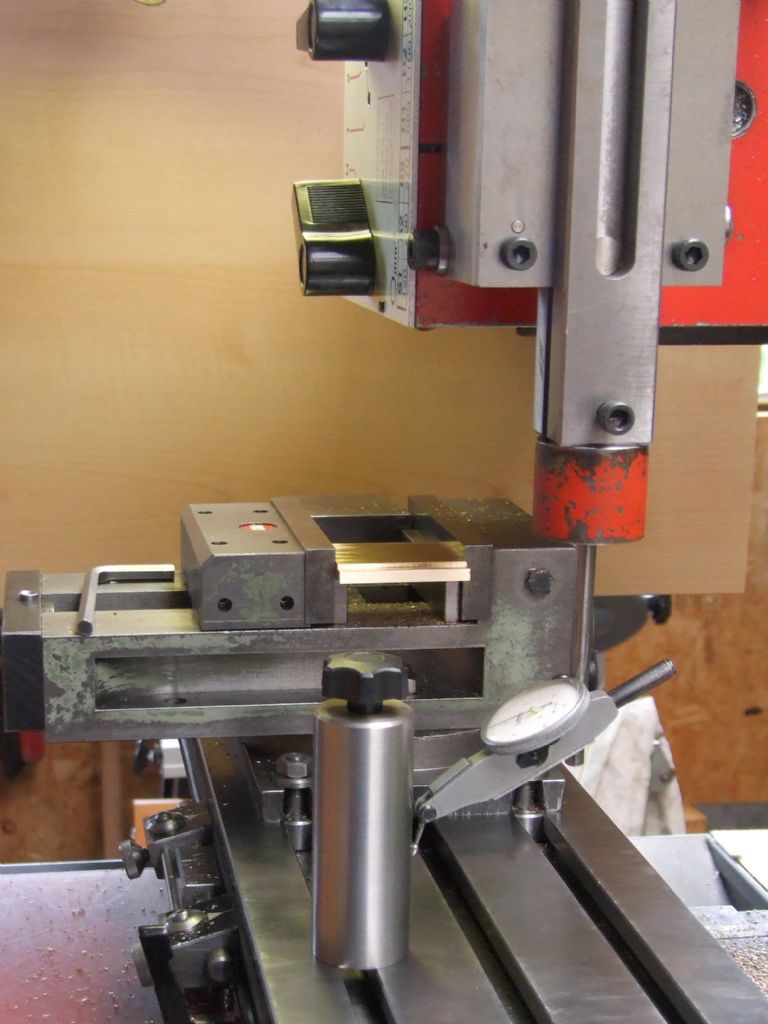
The DTI was then fitted on the table, now to verify column perpendicularity to the table.
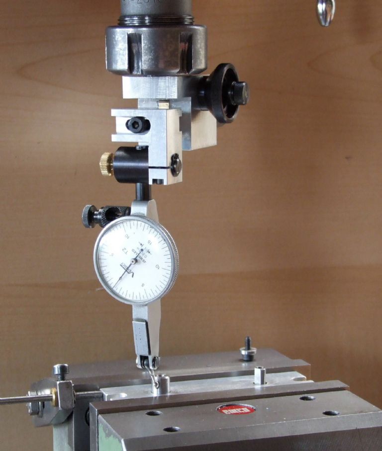
Image below shows test setup for nod – North_South tilt. This required a 0.004mm shim at each top bolt, between column base and Table base.
The same was done with the DTI set on the right of the test bar, for East_West.setting. Final DTI readings were less than 1/3 division.
That was good enough..
North South Column Tilt

Then the last was to set the DTI on the elbow in the collet chuck in the spindle and rotate the dti over the table to check if the reading was good – Table south, 0, table north, 0.002, table east, 0, table west 0.
To qualify, 0.003 is an estimate based on eyeing the needle between division – not easy!
Also, a movement of 0, is not actually 'zero/' but the smallest of needle tip 'wobble' discernable.
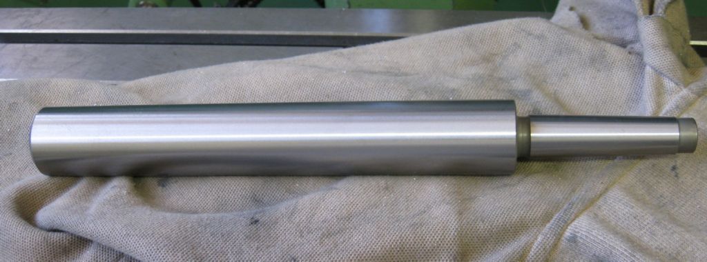
The test bar..

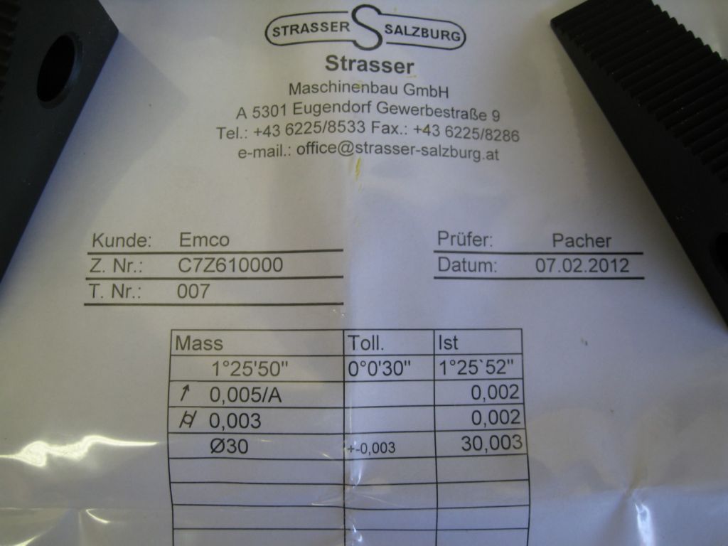
And its certificate..

Can someone explain the meaning of the terms on this certificate?
The diameter of 30 = 30.003, ie, 0.003 error, I understand, but the rest?
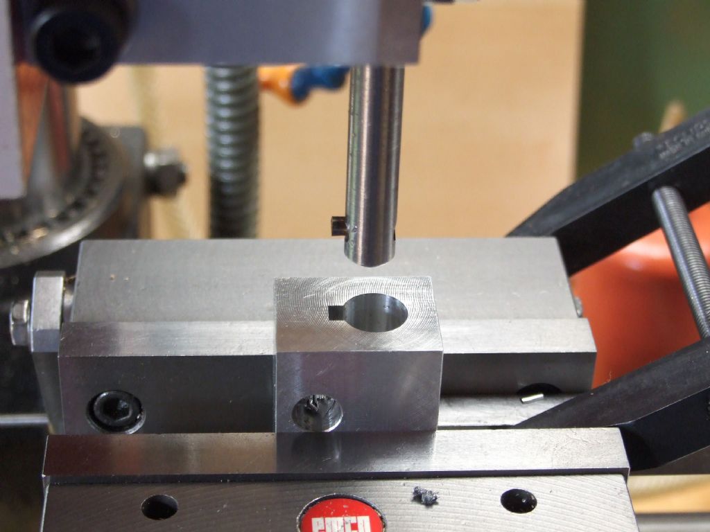
Now ready to start boring..!
Thanks again to all.
Joe
 Ian P.

