Emco FB2 Quirks and Additions

Advert

Emco FB2 Quirks and Additions

Home Forums Manual machine tools Emco FB2 Quirks and Additions

Viewing 25 posts - 26 through 50 (of 84 total)
  • Author
    Posts
  • #491948
    Joseph Noci 1
    Participant
      @josephnoci1

      One annoyance I had with the Emco Quill clamping lever was its tendency to drop down without warning once the quill was released & The Vertical clamping Lever has also been changed to my preferred stud and lever system to which I have added another roller thrust race.


      Excellent solutions here Graham!

      I am going to do the vertical clamping lever ASAP. The quill clamp does not bother me too much, but I use the vertical clamp a lot, especially with the heavier cuts, and find the stiction of the lever quite annoying when fastening/loosening a few dozen times during the process. I never thought of a thrust bearing there! Very neat. I also like the curved setting bar..

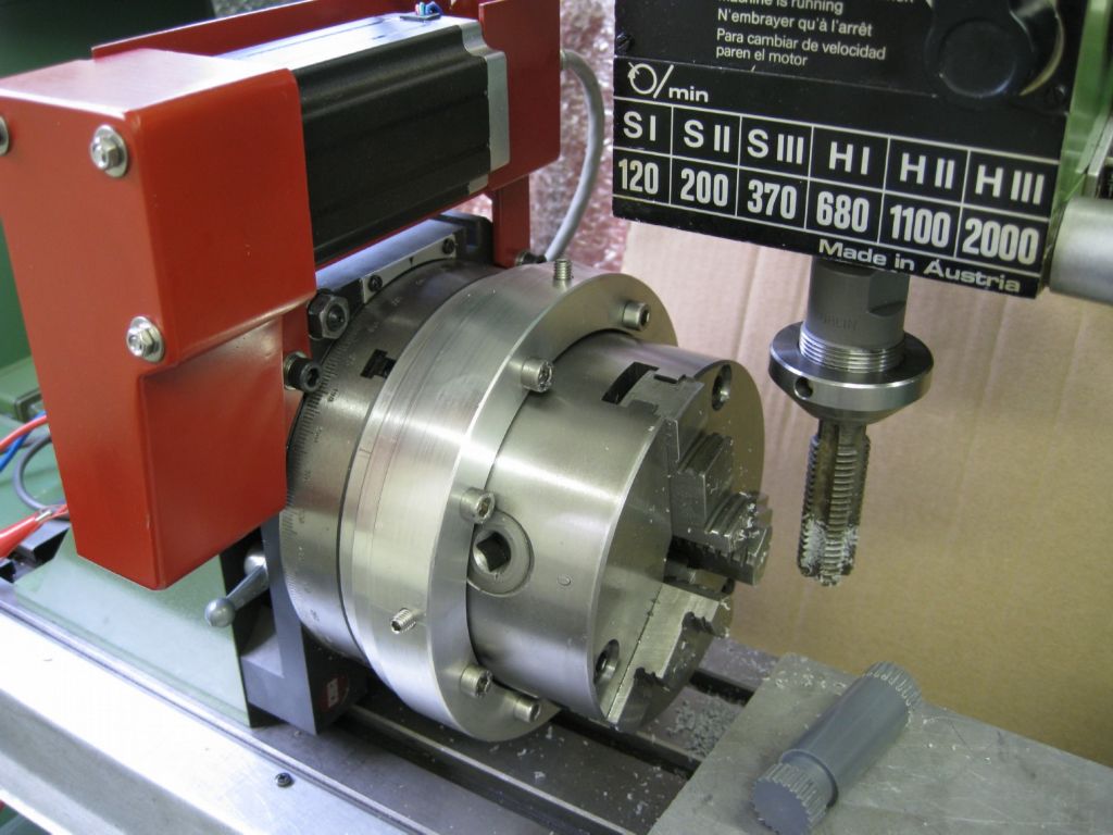
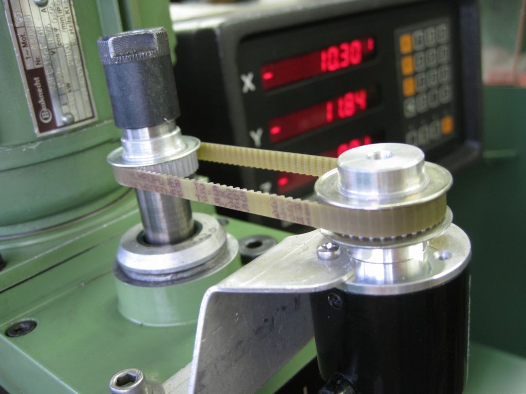
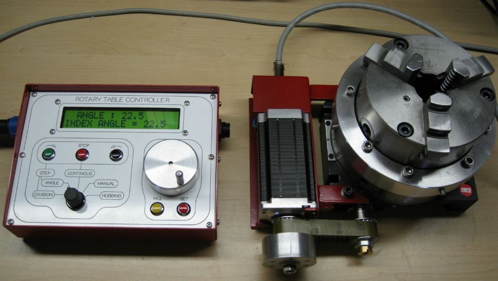
      My EMCO rotary table has been 'computerised' with a stepper allowing quick angle settings, and even continuous rotary motion to allow automated rotary feed for milling circular curves and slots. Fitting a rotary encoder to the FB2 spindle also allows me to do hobbing with the rotary table.

      rotary table on mill table.jpg

      temp encoder mount.jpg


      complete unit.jpg


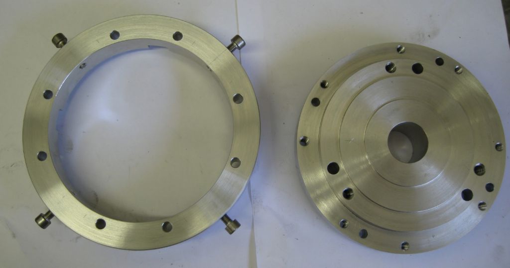
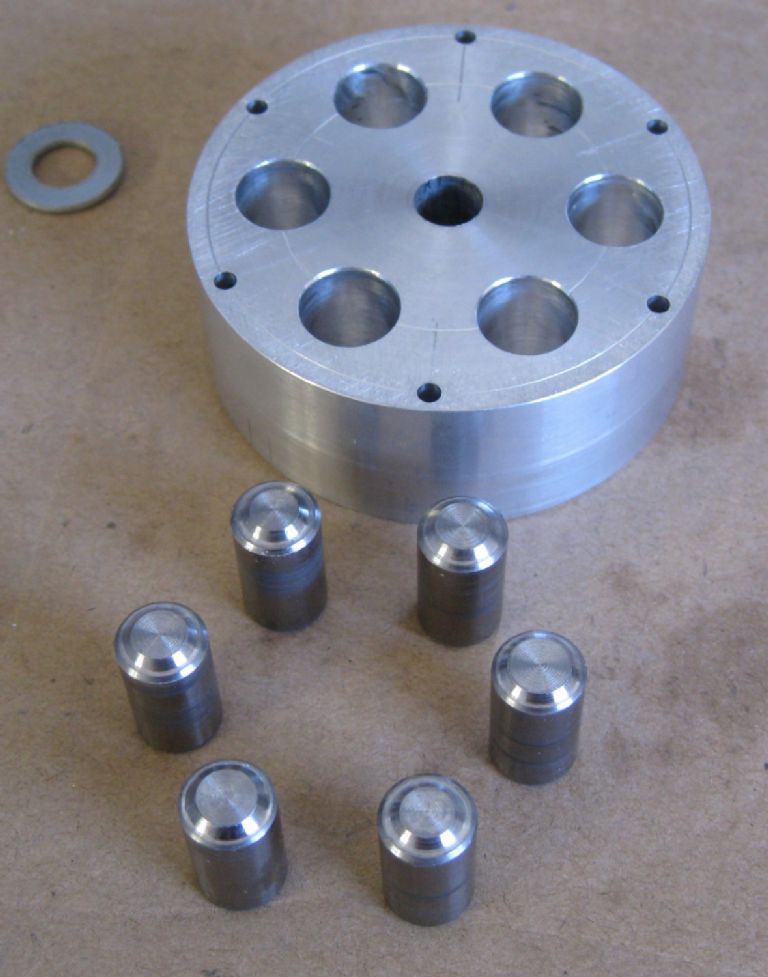
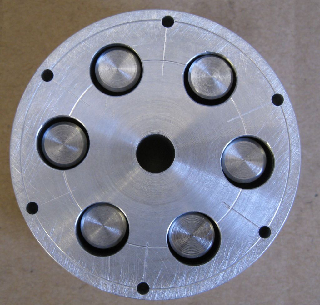
      I also made a sort of Set-Tru arrangement for a fitted chuck – a fixed ring, bolted to the rotary table , with a chuck back plate, a sort of 'slip-plate' that can be centered via the 4 side cap screws, and the the peripheral caps screw bolted down fast. Set up the work piece in the chuck, back of the peripheral fixings, set the table in rotary mode so it turns continuously with a dial gauge on the work piece and adjust as one would a 4 jaw setup. Works well enough for me!

      centering ring complete with backplate.jpg

      Edited By Joseph Noci 1 on 22/08/2020 13:00:11

      Advert
      #492101
      Graham Meek
      Participant
        @grahammeek88282

        Nice work Joe and thanks for sharing your ideas on this post.

        The chuck adaptor is a clever idea, I suspect that would make a good article?

        Is that a Flywheel on the end of the stepper motor drive pulley?

        Regards

        Gray,

        #492119
        Circlip
        Participant
          @circlip

          Refreshing to see a couple of ENGINEERS playing nicely.laugh

          Regards Ian.

          #492140
          Bazyle
          Participant
            @bazyle

            Appologies for a brief hijack on the FB2 subject.
            I notice that Graham's machine is red clearly branded and Joseph's is green. Online pictures of Emco's are mostly green. Did The FB2 get rebranded or cloned? I'm advising an estate from a photo 99% looking like an FB2, that looks like Warco green, definately has no brand name, but nearby is a Warco sticky metal label that looks like it fell off it.

            Edited By Bazyle on 23/08/2020 14:41:18

            #492149
            Graham Meek
            Participant
              @grahammeek88282
              Posted by Bazyle on 23/08/2020 14:39:58:

              Appologies for a brief hijack on the FB2 subject.
              I notice that Graham's machine is red clearly branded and Joseph's is green. Online pictures of Emco's are mostly green. Did The FB2 get rebranded or cloned? I'm advising an estate from a photo 99% looking like an FB2, that looks like Warco green, definately has no brand name, but nearby is a Warco sticky metal label that looks like it fell off it.

              Edited By Bazyle on 23/08/2020 14:41:18

              No problem with hijacking the thread,

              My machine is one of the last to come out of the Emco factory at Hallein, in Austria. The machine was purchased in 1996, the Emco colours were changed with the introduction of a revised electrical layout on the FB2. My machine has the switch gear, low volt transformer, emergency stop and connection blocks housed in the sloping front of the swarf tray.

              The Red, Grey and Black was introduced with the Emco F3 mill, (roughly about 1990), and its sister machines the F4 & F5, (this designation has changed in recent years to F3B or FB3 etc).

              There was a clone which was Red, Cream, (might have been Off-White), and Black, the name of which escapes me, but was only on the market here in the UK for a short while.

              Warco did do a clone, but I think this machine had the Myford Spindle nose. Emco machines are plain at the spindle nose with two spanner flats. (See the spindle lock earlier in this post for a photograph). The base casting on the Warco was also a dead give away with its sloping sides. (This is the same shape as the current Emco Maximat F1 Mill Drill). The motor on the Warco was also of bigger proportions with the ON/OFF switch on the side of the motor.

              However an FB2 head that was originally supplied with the Maximat Super 11 lathe also had the ON/OFF switch on the side of the motor. As the co-ordinate milling table could be purchased separately at one time, for those wishing to make an FB2 mill, by using the lathe milling head. It is therefore possible to have an FB2 with a non standard ON/OFF switch arrangement. The standard switch on a Green machine is on the side of the casting mounted on a detachable metal cover plate, the capacitor is also under the cover plate.

              Finally I do believe Emco supplied a Badged version of the FB2 to AJAX, I think these were Blue, but I have not seen one in the flesh.

              Hope these notes help

              Regards

              Gray,

              Edited By Graham Meek on 23/08/2020 15:58:34

              #492157
              mgnbuk
              Participant
                @mgnbuk

                Finally I do believe Emco supplied a Badged version of the FB2 to AJAX, I think these were Blue, but I have not seen one in the flesh.

                I'm pretty certain that the Ajax machines were Taiwanese. My current machine is a composite – an Ajax base & table assembly (which has sloping sides to the base & was supplied painted a light hammer finish grey) and a column/head assembly that came from Denford's stores & was fitted with the casting that was intended to be mounted at the rear of a lathe bed – this was painted Denford's house turquoise colour, but I think that it had been re-painted. The lathe bed attachment casting has been cluttering up my garage ever since & is available FOC to anyone who wants to collect it !

                Ajax used to be a customer of my last employer. I went to the Bredbury site quite often over a number of years & knew the technical people there well. On one occasion I was over to measure up a lathe to see if we could come up with an add-on automatic component loading / unloading solution for an enquiry they had received & my visit coincided with a general culling of obsolete parts from the stores. I recognised the base / table assembly that was positioned near the skip & mentioned it to my host, who promptly offered to load it into my car rather than the skip – it would have been rude to have refused ! Ajax had stopped selling the machines at that point & it was thought that the head/column had probably been supplied as a warranty replacement at some point.

                I bought the ex-Denford head & column from Mercer's in Cleckheaton, who had bought several direct from Denfords when they were having a stores clearout. Again. I think this was Taiwanese. My first FB2 clone was supplied new to the first owner by Mercer's, who had imported several from Taiwan – these were painted a brightish hammered green & also had the sloping sided base casting. The original owner had stripped the Tufnol drive gear on a couple of occasions & bought the replacement parts (at great expense !) from Ajax until a friend of his(who worked in the toolroom at David Brown Gears locally) made up a couple of bronze replacements – I kept (and still have) the "spare" one when I sold that machine.

                I seem to think that Warco offered two different clones – the early one (which had the Myford nose) was Taiwanese & the later one (called the ZX16 IIRC) was Chinese. The fit & finish on the Chinese version was not as good as the Taiwanese one.

                Chester's Champion mill (which Warco also sold as the ZX15 IIRC) used what appeared to be a copy of the FB2 base assembly with a poorly designed 4 speed belt drive head & nasty column arrangement. This had a copy of the Emco 3 speed feed gearbox, though, one of which I bought at a Chester open day with a damaged motor cover & which fitted on to my Ajax table without any problems, other than the feedrates shown on the plate are for a 60Hz motor, not 50Hz.

                Axminster also offered this style of machine for a while. I seem to think that theirs were Taiwanese as well & were finished in their "house" colours (turquoise /white).

                Last time I looked (a couple of years ago) there was still a Taiwanse MTB offering this model – shame nobody brings it in, as they are good little machines.

                Probably way more information than anybody wanted …..

                Nigel B.

                #492160
                Joseph Noci 1
                Participant
                  @josephnoci1
                  Posted by Graham Meek on 23/08/2020 12:12:05:

                  Nice work Joe and thanks for sharing your ideas on this post.

                  The chuck adaptor is a clever idea, I suspect that would make a good article?

                  Is that a Flywheel on the end of the stepper motor drive pulley?

                  Regards

                  Gray,

                  Graham,

                  The device on the stepper shaft is a 'rattle damper' – I am unsure as to where that name comes from, but it describes the device well. Sort of an inertial flywheel damper, but has constantly varying resonance frequencies, seemingly dependant of the excitation frequency. It works very well! It has enabled much faster accelerations, no more lost steps at the low speed end, etc. The science behind it seems shrouded in witchcraft, which annoys me!

                  Don't wish to contaminate the FB2 thread with too much divergence on dampers, so just a few photo's-

                  the parts.jpg

                  slug in the wheel.jpg

                  #492192
                  Graham Meek
                  Participant
                    @grahammeek88282

                    Nigel B,

                    Thank you for the additional information, I welcome any information on the FB2 and its clones. I have learnt quite a few things from your input and also revived my memory on the other clones.

                    Joe,

                    Thanks for the photographs and the explanation on the "Rattle Damper". I seem to recall in my distant past hearing about this device before, but I cannot recall in what context it was being used. I don't think it was to do with stepper motors.

                    Regards

                    Gray,

                    #492207
                    Bazyle
                    Participant
                      @bazyle

                      Thanks both for such detailed responses to my question. Such extensive information perhaps may get nto the Lathes site.

                      #493251
                      Joseph Noci 1
                      Participant
                        @josephnoci1
                        Posted by Graham Meek on 23/08/2020 20:49:25:

                        Nigel B,

                        Thank you for the additional information, I welcome any information on the FB2 and its clones. I have learnt quite a few things from your input and also revived my memory on the other clones.

                        To add to the variation of FB2's and clones –

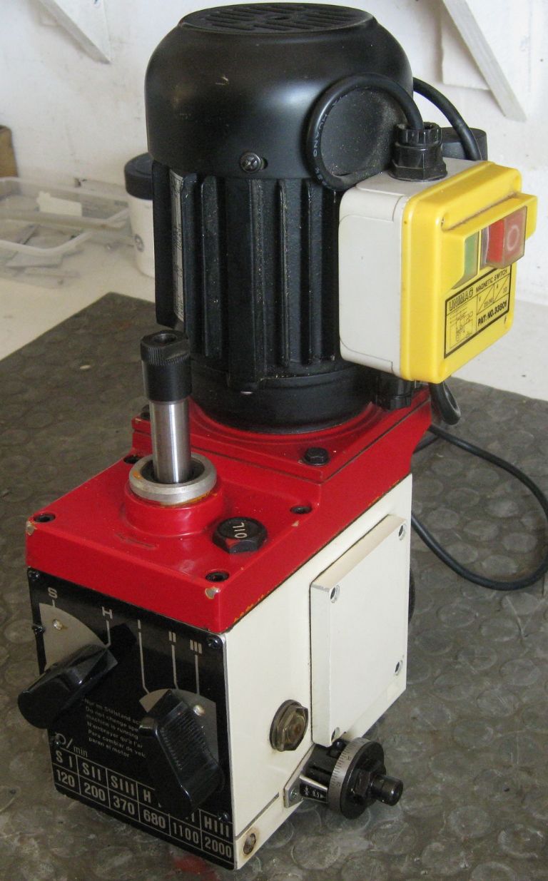
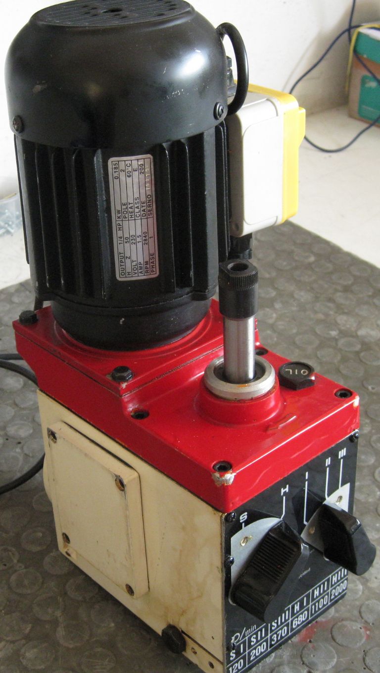
                        I have a FB2 head assembly clone – purchased maybe 15 years ago, that I used as an 'add on' to a horizontal mill.

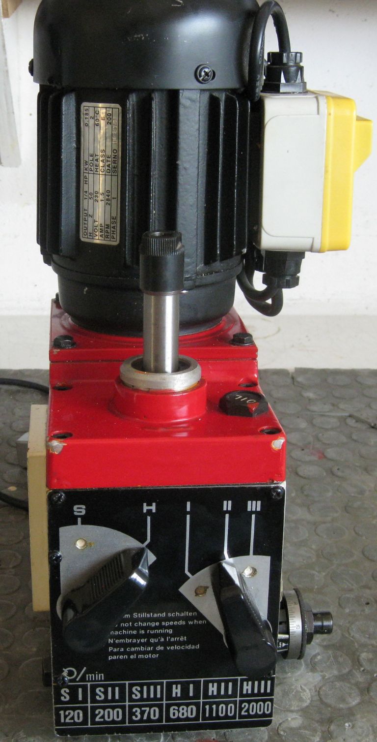
                        It looks like a real FB2, but with the switch assy on the motor – see pics. The quill is good, no measurable runout on the inside of the taper. However, the gearbox differs a lot – no fiber gears, and rather noisy. Also the gear mesh is not great. Compared to the FB2 gear set, the gears are all narrower – by about 20%, and the teeth do not mate to proper depth – as though the gear diameters are under size. It works fine, but the noise is quite irritating!

                        ch_fb2-1.jpg

                        ch_fb2-2.jpg

                        ch_fb2-3.jpg


                        edit – correct syntax..

                        Edited By Joseph Noci 1 on 28/08/2020 20:40:58

                        #493325
                        Graham Meek
                        Participant
                          @grahammeek88282

                          Hi Joe,

                          That is the colours of the machine which I cannot remember the name of. They did a range of machines all based on the Emco products starting with a U3 copy, but were only about for a few years in the UK. I seem to recall they were sold in the USA.

                          I also seem to recall Chester UK supplying a copy with a bright aluminium speed plate, as well as aluminium speed change levers.

                          I think the noise levels of the FB2 were the reason Emco stopped production. The Oil recommended for my 1996 machine is a 68 hydraulic oil, where as before the oil had been 32 viscosity. The heavier oil maybe being used to quieten the noise level.

                          Regards

                          Gray,

                          #495930
                          Graham Meek
                          Participant
                            @grahammeek88282

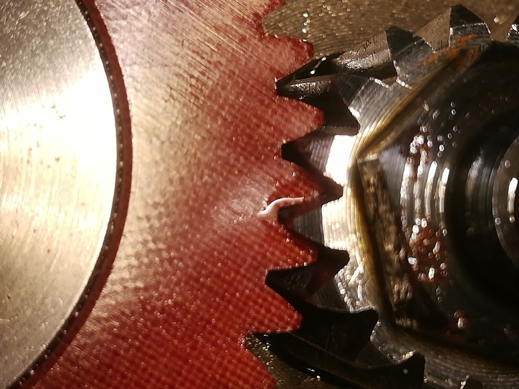
                            A recent inspection of the internals of the Milling Head gearbox showed the teeth on one side of the Sliding Gear showing signs of distress.

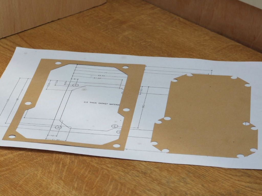
                            Knowing the Gasket or Seal 3 was getting a little ropey on my machine I decided to order one of these along with the replacement gear. Unfortunately since I looked the last time these seals are no longer made. However an email to EMCO in Austria, provided a drawing of the Seal 3.

                            Cutting gaskets by hand has never been my strong point. To make things easier for me I decided to make a drawing of the Seal so that I could use the same hole cutter used for the bolt holes, to also cut all the intersections. As a hand cut gasket I was pleased with the results. It was just a case of laying a rule as a tangent to each hole and cutting through with a craft knife. Sort of Dot to Dot. The holes at each corner not only make the gasket stronger, but take away the awkward niggle of not having cut into the corner enough with the craft knife.

                            Making the Silver steel cutter and the gaskets took about just over an hour.

                            Two gaskets can be had out of one A4 sheet of gasket material, so I took the opportunity to make two of them. The second is inside the machine cupboard door, taped to the door in a plastic bag just in case the next owner needs it.

                            fig seal 3.jpg

                            I think the photograph above illustrates the technique used. If there is sufficient interest for this drawing I will make it available as a PDF, with Neil's blessing and help.

                            Regards

                            Gray,

                            Edited By Graham Meek on 15/09/2020 15:24:51

                            #497511
                            Marcel Bernards
                            Participant
                              @marcelbernards44400
                              Posted by Graham Meek on 23/07/2020 16:52:27:

                              The only Achilles heel with the FB2 from what I have read about is the Tufnol Gear (Gear 47 in the parts List), which some people have had some teeth stripped off.

                              fb2 tufnol input gear .jpg

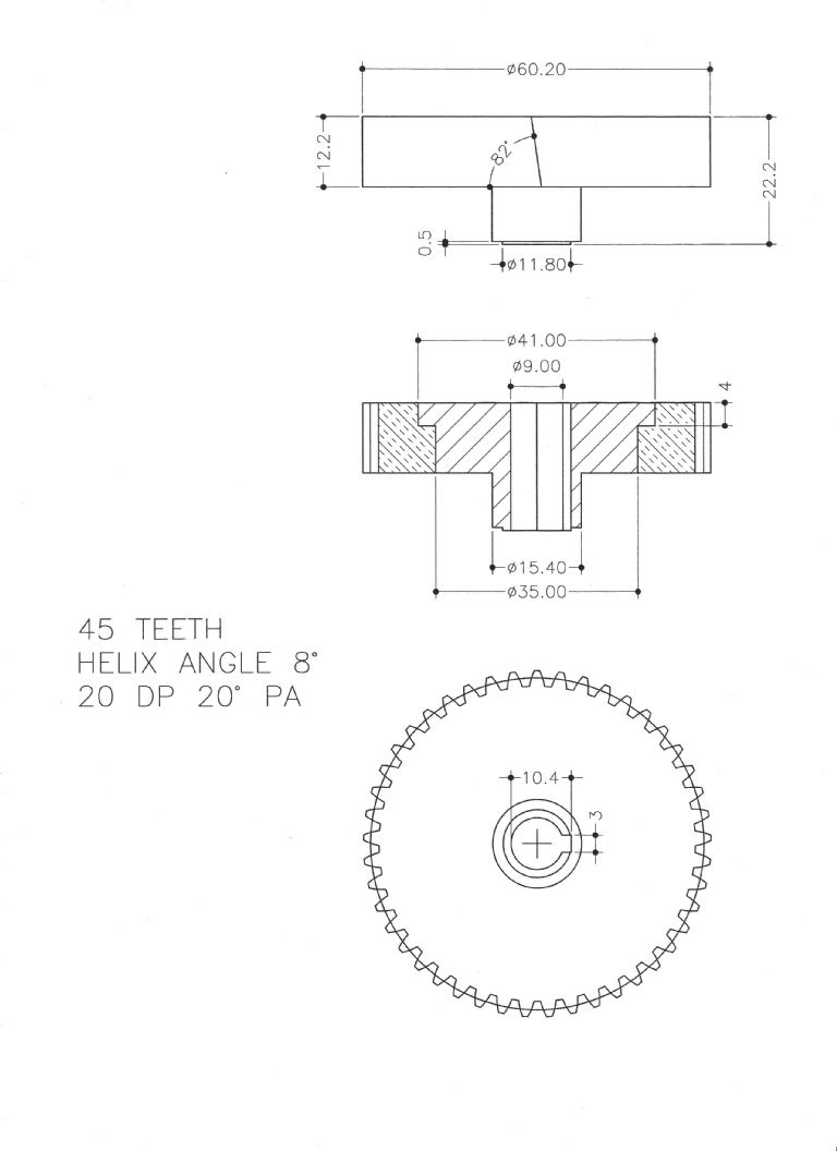
                              I have seen these gears up for auction with the asking price double what a new spare part costs. As many of the parts are no longer being made by the factory. It is just a matter of time before these too will no longer be available. The last time I took the gearbox apart I took the measurements of the gear and have made a drawing.

                              It is interesting to note that the gear is a DP, and not a Module form. Having originated in Austria I did assume the latter, until the sums just did not add up for a 45 Tooth Helical gear.

                              One of the reasons I think these gears fail is due to owners using the lowest gear to lock the spindle to remove any Morse tooling. If one tries to turn the spindle backwards by hand in the lower range there is a feeling that something is binding, just prior to the gearbox locking up. I think it is the Tufnol gear crowding the smaller steel motor pinion.

                              Removing a stubborn Morse taper using this method is going to put things under stress at one point on the Tufnol gear. Unlike when the machine is running and several of the teeth are sharing the load.

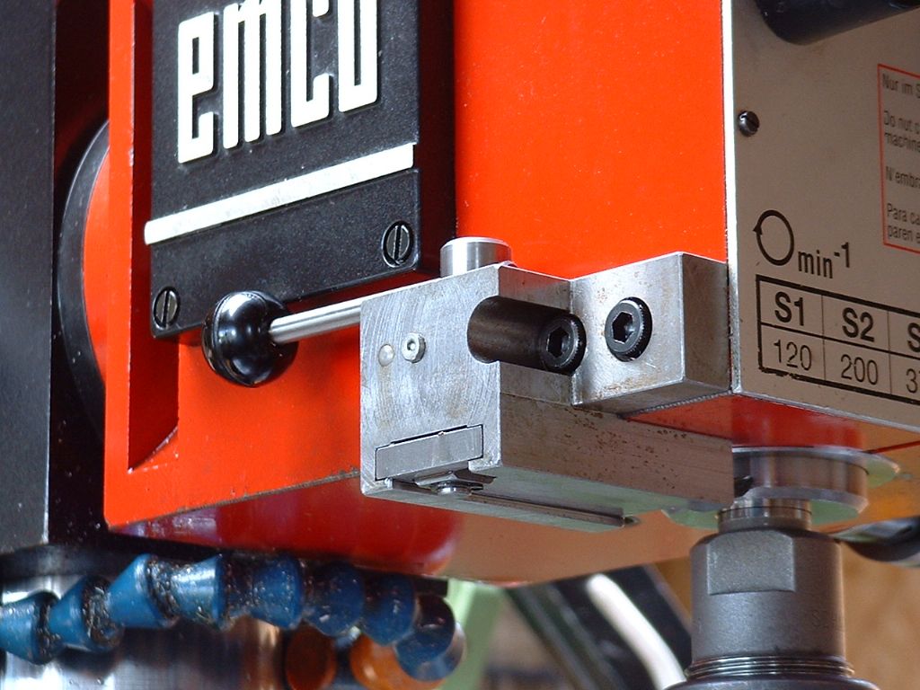
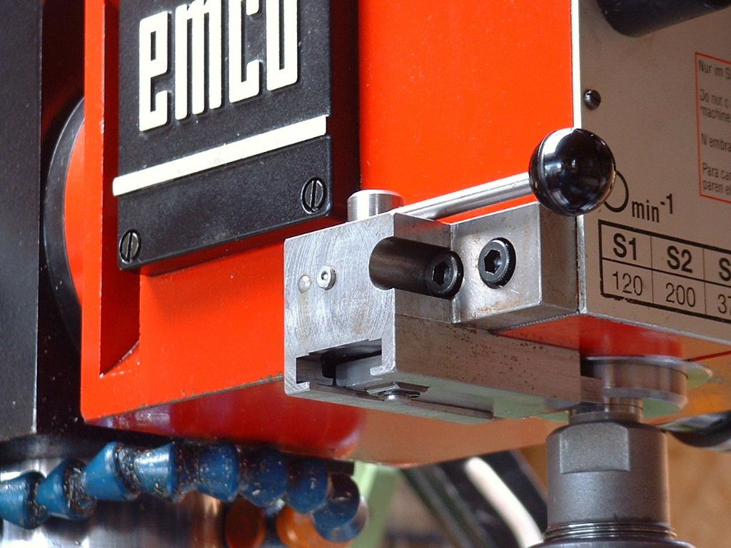
                              To make the changing of tooling much easier and to remove any risk of premature breakage. I designed and fitted the spindle lock below. This makes locking the spindle dead easy and with no risk of damage to any part of the gearbox.

                              fig1 positon of ball handle when un-locked.jpg

                              fig2  ball handle shown in locked position.jpg

                              Over the coming months I hope to try cutting a new 45T gear by simply gashing at 8 degrees. It will not be a true helix but given the gear is 12 mm wide and the Lead is well over a metre, I don't think it will matter. It is certainly worth a try and if it works I shall have a spare to hand.

                              Regards

                              Gray,

                              I just have a question about gear 47 (EMCO part number E3A015000).

                              I had an accident on my Huvema Fv320-T , which is a FB 2 clone machine. Broken gear teeths ….

                              The former owner made a replacement of aluminum but is is noisy as hell and not very well machined. So I ordered one at **LINK**.

                              Inspecting the gears I counted 47 teeths instead of 45, so whats going on here exactly?. My brother has the same machine as I have and his one is also a 47 teeths gear. it is 20DP/Module 1.25 and about 60mm diameter.

                              #497538
                              Graham Meek
                              Participant
                                @grahammeek88282

                                Hello Marcel,

                                I am not familiar with the make of your machine. I have seen advertised non-Emco replacement gears of both 45 teeth and 47 teeth from the same supplier. The price was eye watering and dearer than a genuine Emco.

                                I was bemused with the title of the gear in the Parts Handbook as being Gear 47. The last time I had my machine apart I did count the number of teeth on my Tufnol gear, and it is 45 teeth. The Outside diameter being 60,2 mm. I have also just counted around the not very good image on Pro-Machine Tools web-site and I make that 45 to 46T, but not 47T.

                                I did wonder in the mix of these machines if Emco used a higher number of teeth on those machines fitted with 60 cycle , Hz, motors. However having just worked through the increase in rotational speed of the 60 Hz motor. The speed advisory plate for these machines comes out as one would expect, using the same gearing as a 50 Hz motor.

                                The only other reasonable explanation is that it was originally 47T, but due to breakages the tooth count was reduced to 45T thereby producing a stronger gear. It would be interesting to know if a 45T will run in a 47T machine, as this would prove it.

                                Thus I too am at a loss as to why these gears are different. If anyone has the real reason for this conundrum I would be glad to hear it. I do not like sending anyone off on a wild goose chase.

                                Regards

                                Gray,

                                #497762
                                Marcel Bernards
                                Participant
                                  @marcelbernards44400

                                  Thank you Gray for sharing your knowledge about this machine.

                                  I called Machine shop Bos here in NL who makes in house produced replacements, but he is completely sold out and he is not going to produce new ones as I understand because he is closing the shop soon.

                                  It appears he used other material than the brown tufnol material, probably Nylon or Nylatron

                                  My brother had a replacement put in a few years agoo and probably that was a wrong one, because just after running it for the first time it immediately broke down again. Probably he put a 45T into a device expecting a 47T gear. after ordering another at a differrent supplier its still in working condition.

                                  He is working on a drawing for printing one on his 3D printer. I might try to mill one myself once the new gear arrives.

                                  #498489
                                  Marcel Bernards
                                  Participant
                                    @marcelbernards44400

                                    Just today I received my new gear from Austria and guess what!

                                    I counted 45 tooth. dont know

                                    I inspected the motor drive gear and it counted 17 tooth

                                    I fitted both gears in the motor gear and the new one 45T seems to fit better and turn smoother

                                    So I think Gray you might be right that later mills use 45 teeth

                                    My clone mill is from 1998 according to the label

                                    outside diameter 60,7mm of the new one

                                    Edited By Marcel Bernards on 29/09/2020 16:51:30

                                    #498494
                                    Graham Meek
                                    Participant
                                      @grahammeek88282

                                      Hi Marcel,

                                      Thanks for the update, it is nice to get some feed back that verifies the above drawing, other than just my memory. It is also good to know the Motor Pinion tooth count, as to date I have not counted this. My own mill from Austria was manufactured in1996. I was told it was one of the last to be produced, how true that is I do not know.

                                      Regards

                                      Gray,

                                      #498529
                                      Marcel Bernards
                                      Participant
                                        @marcelbernards44400

                                        I learned a lot in this thread about this FB2 and clones. Love it.

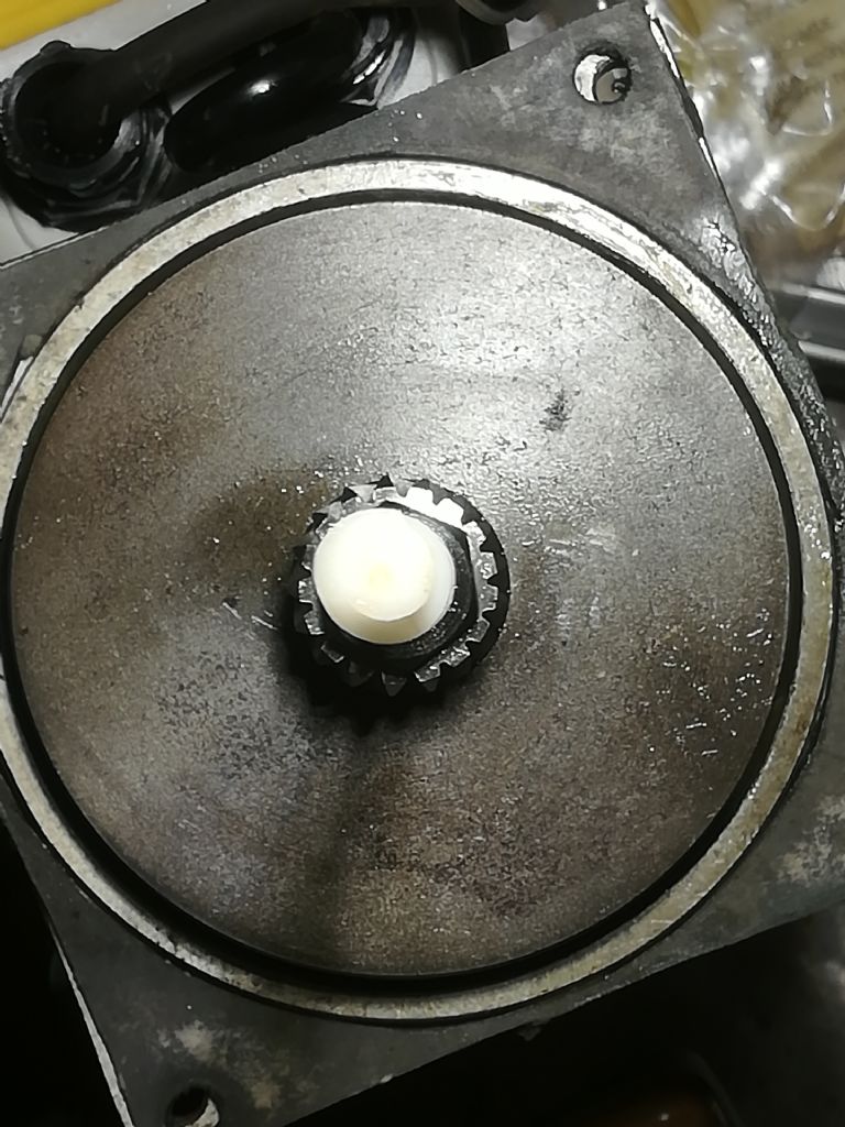
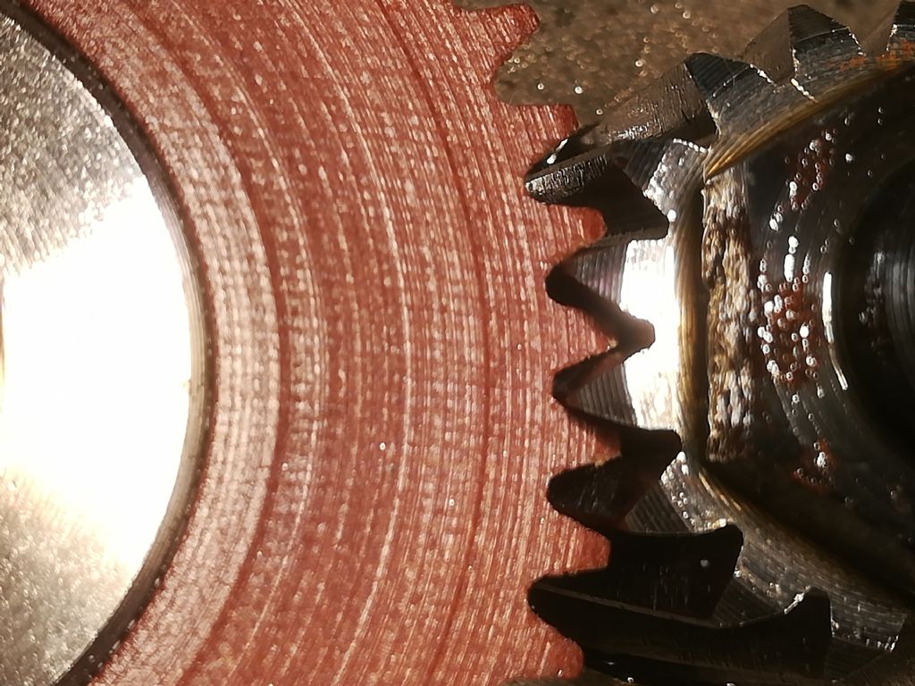
                                        I made some pics to share in an album img_20200929_203025.jpg

                                        drive gear 17T i inch outer diameter

                                        img_20200929_174031.jpgnew gear fit 45T

                                        img_20200929_174057.jpg

                                        old gear 47 T

                                        Since I opened up my mill a few times and the gasgets are getting worse a drawing PDF of the top gasket would be nice. the motor gasget is a simple one. 113x113mm square with a hole of 108mm and 4 6.5mm holes 98mm square

                                        #498618
                                        Neil Wyatt
                                        Moderator
                                          @neilwyatt

                                          Graham has kindly sent me a PDF with a drawing of the gasket seal to upload. I changed the name to make the link simpler.

                                          You can access it here:

                                          http://www.model-engineer.co.uk/wp-content/uploads/sites/4/documents/EMCOSEAL_GM.pdf

                                          Thanks Graham,

                                          Neil

                                          #498640
                                          Marcel Bernards
                                          Participant
                                            @marcelbernards44400

                                            Fantastic, thanx Neil

                                            #498644
                                            Michael Gilligan
                                            Participant
                                              @michaelgilligan61133
                                              Posted by Neil Wyatt on 30/09/2020 11:58:20:

                                              Graham has kindly sent me a PDF with a drawing of the gasket seal to upload. I changed the name to make the link simpler.

                                              You can access it here:

                                              .

                                              Lovely quality image … beats a jpg hands-down.

                                              MichaelG.

                                              #498655
                                              derek hall 1
                                              Participant
                                                @derekhall1

                                                Thanks Graham,

                                                Good to look at what you are doing with your Emco FB2……I will copy all of your modfications on to my FB2!

                                                …..and thanks to Neil for the pdf

                                                Regards to all

                                                Derek

                                                #498684
                                                Graham Meek
                                                Participant
                                                  @grahammeek88282

                                                  Hi Derek,

                                                  I am glad you like this post, and good luck with the modifications. I have certainly learnt a few things from other contributors regarding the clones.

                                                  Regards

                                                  Gray,

                                                  Edited By Graham Meek on 30/09/2020 18:07:50

                                                  #505197
                                                  Joseph Noci 1
                                                  Participant
                                                    @josephnoci1

                                                    FB2 users, how do you go about tramming the mill?

                                                    I need to do some rather delicate and accurate, deep , large diameter boring on the FB2, and need to tram the machine really well.

                                                    I have set the column perpendicular to the table – set up an accurate refence cylinder square (100mm diameter and 200mm tall) on the table with a DTI in the spindle. Then run the head up and down with the DTI rubbing the west side of the square and adjust the column left/right.

                                                    Then to repeat the process with the DTI on the South face of the cylinder square for forward/rearwards column tilt. But how best to adjust the forward/rearward tilt of the column? I did by means of paper thin spacers at top or bottom of the column support base but that is really fiddly. Is there another way?

                                                    As the head can tilt left and right, I then keep the complete head in fixed position, DTO on west side of the square, and using the quill feed, run the DTI up/down the square, and adjust the 2 tilt bolts while fiddling the head vertical.

                                                    Now, after doing all that, with the column pretty close to perpendicular north/south and east/west, and the head set properly vertical in east/west, I then put the usual DTI on the end of a long arm, in the spindle, and rotate the DTI over the table in a circle. Expecting a decent dial readout, I was rather disappointed…The DTI reads high (0.2mm..!) on the table surface closest to the operator, and zero on the table near the column. Left and right are equal, at around 0.08mm….

                                                    I spent most of the morning doing this, over and over….I rechecked – the column is perpendicular within 0.01mm over a 180mm height on the south and west sides of the square. I checked the square – rotating the square 90deg and 180deg shows the same 0.01mm deviation.

                                                    It would appear that the spindle head ( ie, the quill and head) has some 'nod' – is 'drooping' down and I don't see how to adjust this – not in the manuals, and not evident in the parts breakdown either.

                                                    Any advice will be most welcome!

                                                    Joe

                                                    #505222
                                                    Kiwi Bloke
                                                    Participant
                                                      @kiwibloke62605

                                                      Hi Joe,

                                                      Judging from the quality of your many previous posts, I'd bet that your understanding of this machine's adjustments is as good as anyone's. There is indeed no adjustment for verticality that you haven't already explored, so I suppose it would be a matter of tearing it down and checking on the surface plate, etc.. If it turns out that the quill bore and the bore for the vertical column can't be adjusted to be parallel, there's a real problem, isn't there?

                                                      The lack of a proper adjustment mechanism for the column's verticality is an unfortunate omission. You could add jack screws…

                                                      Just one idea, however, offered because we all have transient blind spots… Is the head carrier (or whatever it's called) clearance to vertical column really well adjusted? I thought mine was, and that chatter during some heavy boring was showing the limit of the machine. However, after tightening the clearance – to the extent that the head didn't fall unless pushed down by the raising screw, there was a vast improvement. Then had to be careful about vertical travel backlash, of course. Does the vertical travel clamp/lock affect the 'droop'?

                                                      I'm sure you're aware that drilling machine tables are often aligned intentionally a little high at the operator's side, so that, under drilling forces, the hole goes (more nearly) truly vertically, as the machine springs, but I can't believe that Emco would have built in 0.2mm 'compensation' – that seems a lot (but perhaps isn't, depending on the length of the dial-carrying arm).

                                                      Hope this helps.

                                                    Viewing 25 posts - 26 through 50 (of 84 total)
                                                    • Please log in to reply to this topic. Registering is free and easy using the links on the menu at the top of this page.

                                                    Advert

                                                    Latest Replies

                                                    Home Forums Manual machine tools Topics

                                                    Viewing 25 topics - 1 through 25 (of 25 total)
                                                    Viewing 25 topics - 1 through 25 (of 25 total)

                                                    View full reply list.

                                                    Advert

                                                    Newsletter Sign-up