Emco FB2 mill – weird Z position shift

Advert

Emco FB2 mill – weird Z position shift

Home Forums Beginners questions Emco FB2 mill – weird Z position shift

Viewing 7 posts - 26 through 32 (of 32 total)
  • Author
    Posts
  • #584558
    Y C Lui
    Participant
      @yclui16187
      Posted by Kiwi Bloke on 08/02/2022 08:05:56:

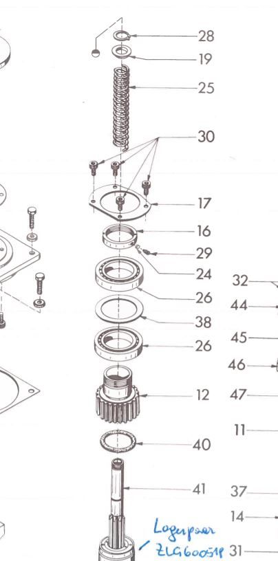
      …. I'd still like to understand what the spring is for, though….

      I think the spring is to keep the quill/spindle retracted into the head when the quill feed handle is let go. The lower end of the spring rests on parts #12 which is kept in place by the housing of the head. The upper end pushes parts #19 , which is attached to the upper end of the spindle upward. There is another coil spring in the quill feed mechanism so may be the question is why two springs are needed.

      spring.jpg

      Advert
      #584567
      Kiwi Bloke
      Participant
        @kiwibloke62605

        Oh, good grief! Of course it does! Thank you. What a monumental blind spot! Clearly, I'm losing it…

        #584577
        Graham Meek
        Participant
          @grahammeek88282

          The small torsion spring fitted to the Quill feed pinion is to return the Drilling Depth Stop to zero. It has no part in returning the Quill, this is taken care of by Detail 25 above.

          I did forget to respond to your query concerning the 0.04 mm error in the Y-axis. (You are not alone Kiwi Bloke when it comes to losing it). My machine too has a similar error but only 0.03 mm over the 200 mm parallel in the Y-axis. It was something I discussed with John Slater a while back.

          While the error is present with the Head close to the table, it disappears with the head at the top of the column. Now there is a conundrum. I concluded, rightly, or wrongly, that the weight of the milling head induced a bending moment in the column. Thus as the head is raised from the table the error diminishes. There is more often than not a milling vice, or a rotary table on the table, and this does not include the drill or collet chuck protruding from the spindle. The milling head usually spends most of its time half way up the column.

          Thus I concluded to leave well enough alone as it was probably what Emco intended. The fact that your machine has a similar reading leads me to believe this is the case.

          Regards

          Gray,

          #584799
          Chris Mate
          Participant
            @chrismate31303

            Hi, just further curious about this.

            Say you turn a test piece in a lathe with with a round tip as had already been done, but now above the round tip you turn a 5-10mm thick quare shoulder on this test piece and insert it in thec spindle.

            Now you add the set indicator at the bottom touching the round piece, and add another dial test indicator resting on this turned shoulder. Now my question is what does the 2nd indicator indicate as the lower set indicator is deviating as the rotation is reversed-? I am I right to assume if the dial test indicator show no deviation, nothig has happenned in the spindle as it was reversed by hand-?

            Edited By Chris Mate on 09/02/2022 16:49:15

            Edited By Chris Mate on 09/02/2022 16:49:49

            Edited By Chris Mate on 09/02/2022 16:50:32

            #584803
            Graham Meek
            Participant
              @grahammeek88282

              Hi Chris,

              What you suggest amounts to the same test I did using a clock on the end of the spindle, while rotating the two lever clocks.

              Admittedly the surface I was indicating off had not been ground. It did give a consistent High and Low spot, which was only 0.01 mm, and not the original 0.05 mm. Which for a post heat treatment surface was pretty good in my book.

              Your test does however rely on the collet running dead true. Any run-out in the collet would make the flange wobble, even so your method should be a lot nearer than the original tests.

              Regards

              Gray,

              #584815
              Chris Mate
              Participant
                @chrismate31303

                Hi, If I understood the original test correctly, its only the difference indicated when the spindle changed direction in turning by hand, and that happened anywhere in one circle the spindle turn. So that mark/identify this argument, ignoring other forms of runout. This was an up/down movement not expected.

                Now I would like to see if this particular induced up/down movement is from the spindle. So in my suggested method, if it shows on the tool set indicator as soon as direction is reversed any place in one circle, what would the 2nd dial test indicator indicate on a flat surface not on the outside but on the top side of a surface machined that can only reflect up/down movement of the spindle under correct circuimstances. If it needs to be grinded ok, then so be it for those that can do it. My idea is still measuring on a round but flat surface unlike the tool set indicater pointed upwards towards a roundy pointed surface.

                Note:Maybe the idea I suggested must be cut in a lathe 1st, then placed in the spindle a re-cut truely with lathe cutters positioned to do that. I have seen another guy on youtube cutting on a mill like in a lathe, then you know it runds true to the spindle, and only the up/down movement in question should reveal or totally disappeear and changed to a new direction based on true cut to the spindle in question-?

                I am I correct understanding it like this-?
                 

                Edited By Chris Mate on 09/02/2022 20:32:52

                #584831
                Kiwi Bloke
                Participant
                  @kiwibloke62605

                  I'm a bit wary about contributing again, having made a fool of myself over the spring, a few posts back. The stupid thing is that I knew about the spring, a long time ago, but had forgotten and now got confused. It's an age thing, I suppose, and it's only going to get worse <sigh>.

                  Chris: yes, I think I understand what you're suggesting, however previous posts have suggested test set-ups which are, I believe, equivalent. Graham Meek and myself have 'clocked' the end of the spindle: it may not be absolutely 'flat', but if it's not quite flat, or if its surface is tilted wrt the spindle axis, any error due to these causes will show up as cyclic errors, or a pattern of deflection that repeats each revolution. That isn't what the original video shows, although, to be pedantic, one has to infer that from the spindle being turned approx. 180 degrees each time, rather than continuously. We could be seeing a cyclic error, but let's be generous to the OP and assume that's not the case.

                Viewing 7 posts - 26 through 32 (of 32 total)
                • Please log in to reply to this topic. Registering is free and easy using the links on the menu at the top of this page.

                Advert

                Latest Replies

                Home Forums Beginners questions Topics

                Viewing 25 topics - 1 through 25 (of 25 total)
                Viewing 25 topics - 1 through 25 (of 25 total)

                View full reply list.

                Advert

                Newsletter Sign-up