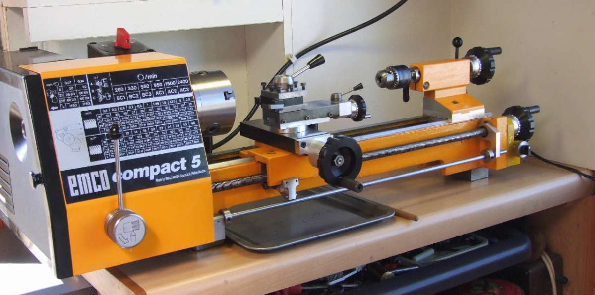
Emco Compact 5 Modifications
Emco Compact 5 Modifications
Home › Forums › Manual machine tools › Emco Compact 5 Modifications
- This topic has 115 replies, 12 voices, and was last updated 11 June 2025 at 12:21 by
Graham Meek.
-
AuthorPosts
-
17 June 2024 at 13:20 #736546
Pete
Participant@pete41194As always wonderful, well designed and thought out Gray, and certainly better than my use of a DI with an enlarged “elephants foot” tip on it. Mine works well for tools in there normal orientation, but as you pointed out yours can also work with the tools inverted. A very cleverly designed tool in my opinion.
Fwiw, I have an old book that shouldn’t be impossible to find a used copy of even in the UK that I think you’d find of great interest. It’s one in a series from the American Machinist Library titled Tool and Gage Work and written by C.L. Goodrich & F.A. Stanley. No ISBN no. of course since that was before the ISBN system was invented. It was first published in 1907 by McGraw- Hill and mines a 1923 second edition.
In it there’s a description and working drawings for a dial less but high multiplication early form of DTI. Starrett Tools at one time produced one much the same. They show using a shop built version of it, a set of shop made hardened and ground tool maker buttons, and positioning by hand with a micrometer and that DTI master gages for a typewriter manufacturer on a sleeve bearing lathes face plate to under 10ths accuracy for boring and finish grinding. All done before jig borers and grinders were even invented.
There’s also a full chapter on what must have been the very first set of Johansson gage blocks in North America, and they speculate how they might ultimately be used by industry. Quite remarkable just how accurate those predictions turned out to be.
17 June 2024 at 13:50 #736554Graham Meek
Participant@grahammeek88282Hi Pete,
Thanks for the kind comments and the reference to the book. I will definitely try and search that one out. I did see the Starrett and Verdict patents in amongst the ones John sent me. It was the simplicity of the Verdict patent that started me off on this current design.
I seem to recall Ford buying out the Johansson business, but I am not that sure I am correct. At the time I seem to recall thinking it was something you would not associate the mass production techniques of Ford with. I am almost sure I have a few odd gauge blocks made by them in my small parallels tin.
Regards
Gray,
17 June 2024 at 18:38 #736580Pete
Participant@pete41194You very welcome Gray.
The history of the Johansson company is a little murky. As far as I know, Johansson after introducing those gage blocks into the U.S. started out in America and had Ford as a partner. Apparently as soon as Henry Ford saw his gage blocks he was convinced they would be an instant success. I believe but don’t know for sure Ford bought Johansson’s gage block production facility some time later, but the early gage blocks were stamped with Johansson’s name as well as having the Ford logo on them. I’m pretty sure the rest of Johansson’s business in Sweden was never any part of his partnership with Ford and was always a separate entity. Another guess, Johansson likely used the sale of his share of the gage block facility and reinvested it back in Sweden. Around that time or slightly later he brought out his Mikrokator, a very high accuracy plunge indicator. I’m fairly certain his initial design was used and adopted later after the patent ran out by at least a few other manufacturer’s. I’ve read that most of Johansson’s internal design for those Mikrokators is still used in the Mitutoyo millimess indicator I have that’s actually built and labeled with the Mitutoyo logo by Mahr. Afaik the only real difference between the Mahr indicator and mine is a simple plastic bezel with that injection molded Mitutoyo’s logo on it.
I know the Johansson company also manufactured very high precision indicator test stands for use with his indicators. Beyond that, I’m not sure what else they produced. Today those indicators and test stands can usually be picked up at fairly reasonable prices since not that many are now familiar with the name or the history. Even Starrett and Mitutoyo still make indicator test stands to the same general design that Johansson used.
One often repeated story about those first gage blocks was that Johansson produced the first few sets using a converted treadle driven sewing machine to lap them flat, parallel and square to those low millionths of an inch accuracy. Since Johansson would have been trying to protect his patent and keep his methods secret, I’ve always been a bit suspicious as to just how valid that story was. But I’ve yet to figure out how he did manage that level of accuracy given the technology available at the time.
17 June 2024 at 20:24 #736590Graham Meek
Participant@grahammeek88282Hi Pete,
Many thanks for the update on Johansson. I have learnt something new today, thanks for that. I seem to recall a pair of Gauge blocks wrung together with a large weight hung from the lower block.
I too wonder how they managed to achieve the finish and accuracy back in those days. Getting something flat is one thing but to get that flat parallel to another flat and to within half of nothing is quite a different matter. It is thanks to their determination to strive for something better that we have such good equipment today.
Regards
Gray,
18 June 2024 at 06:58 #736614Pete
Participant@pete41194Well unfortunately I seem to have taken your thread a bit OT Gray. But I guess some of it is at least remotely related to that very clever gauge you came up with.
In that book I mentioned, they show two gauge blocks wrung together and with a weight of 11.75 lbs suspended from them. So even back in the early 1900’s, they knew and could calculate the surface area that there was much more than atmospheric air pressure holding them together. They just didn’t fully understand the exact reasons. Most today agree it’s caused by what’s known as the Van der Waals effect or force in combination with lesser effects like that air pressure and possible surface tension at the molecular level.
Two surface flat enough to wring together would be tough enough. Doing the same in all 3 dimensions, parallel and to low millionths level for those surfaces, and then to extremely accurate sizes, plus accomplishing all that for each set of blocks, is as you say quite a different matter. Afaik and from my limited information about it, manufacturer’s around that time period and prior to Johansson’s gauge blocks already manufactured there own various sized single blocks to suit there own in house gauging requirements and used as there own reference standards. Obviously and without the specialized lapping and measuring equipment, the true sizes and finished accuracy could vary a bit. It was also considered a large, ongoing, costly as well as time consuming effort by those same manufacturers.
Johansson’s invention gave them high precision size standards to use within at least known amounts of deviation, and in my opinion, that ability probably accelerated the previous ideas about interchangeable parts. Or at least made it much easier. I also think once they started being adopted as standards and if you consider a bit of manufacturing history, you also started seeing many more standards being put in place between the early 1900’s and WW II. Fully agreed to and formal standardized thread sizes and pitches world wide would be just one example. Johansson’s gage block invention may not have been the single and only reason, but to use a bit of logic, they might well have been a large part of it.
18 June 2024 at 20:21 #736736 Michael GilliganParticipant@michaelgilligan61133
At the significant risk of creeping this topic even further:
https://www.nist.gov/system/files/documents/calibrations/mono180.pdf
… it’s long, and quite techincal.
MichaelG
19 June 2024 at 10:21 #736790Graham Meek
Participant@grahammeek88282No Problem Michael,
I am always open to learning something new about Engineering. The subject was touched upon in my ONC years but I must say my memory will not recover that information.
To get us back on track here is the Mk1 version which was too big.

Regards
Gray,
29 July 2024 at 15:03 #744153Graham Meek
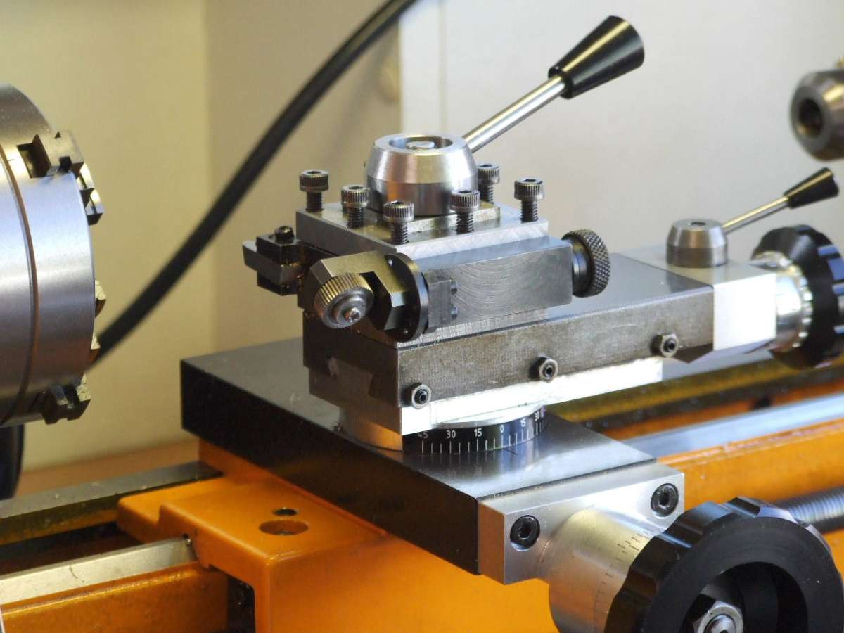
Participant@grahammeek88282Twenty years of wear on the knurling of the Feed screw Handwheels on the C5 had reached the stage where I could not grip them very well any more. While new handwheels are still available from Austria. I decided to make some new ones similar to the ones I made for the Unimat 3 that I have. An example of this type can be seen on the C5 Topslide.

I also took the opportunity to alter the cone angle of the handle to give better access when adjusting the dials. The revolving handles were also changed. The new ones are parallel and made of steel. The tapered plastic Emco ones were also showing a lot of wear. The handles revolve on a commercial 6.5 mm diameter x 25 long Shoulder screw. This has an M5 thread and screws directly into the Delrin handwheel. A custom steel washer abuts the shoulder screw and increases the contact face with the Delrin. This washer also stops the handle from wearing into the Delrin over the years to come.
This mod was done some weeks ago, but today was the first chance I have had to get a photograph.
Regards
Gray,
14 August 2024 at 18:27 #747010Graham Meek
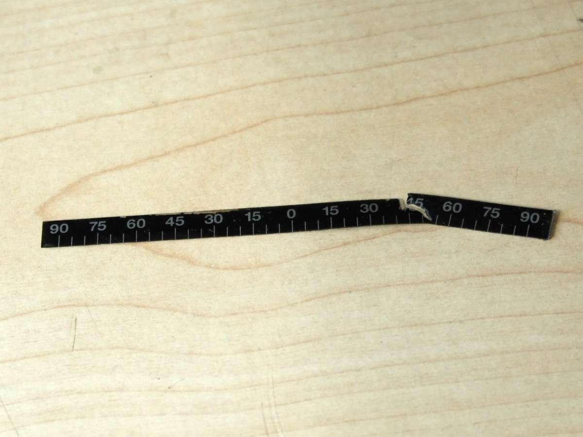
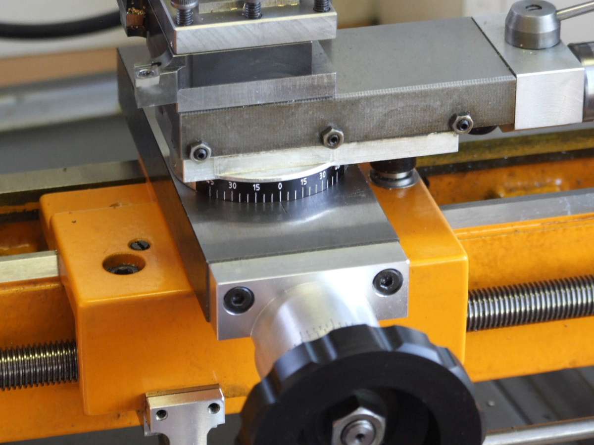
Participant@grahammeek88282This modification was not part of my original plan. Whilst watching the swarf coming off a rather long workpiece. I had failed to notice the free end which was snaking around the top-slide base. Before I had a chance to react the coil of swarf had deftly removed the C5 Top-slide degree scale.

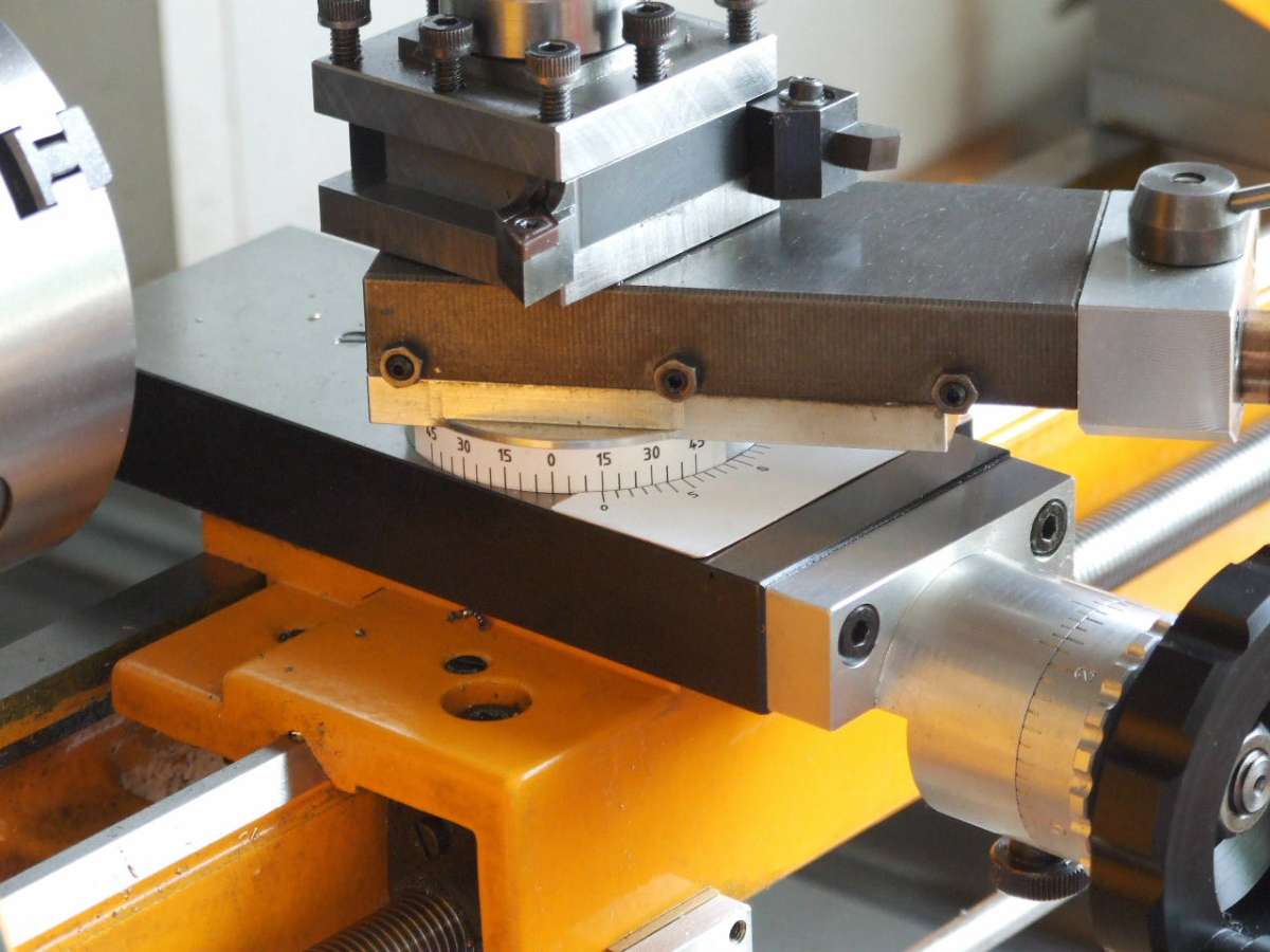
This scale had been an annoyance in that is was impossible, at least for me, to see graduations on the scale past 45 degrees either side of Zero due to the overhang of the top-slide.
My initial reaction was to make another scale but an engraved one in Brass. This was going to be a lot of work, so an alternative was needed. I did wonder if it was possible to get inkjet printable sticky Vinyl sheets. This was later confirmed following a google search.
Thus I decided to draw up some new scales using Qcad. From the outset it was deemed pointless doing 90-0-90, instead 45-0-45 seemed a better option.

To make up for the missing 45 degrees a separate scale on the cross-slide was needed.

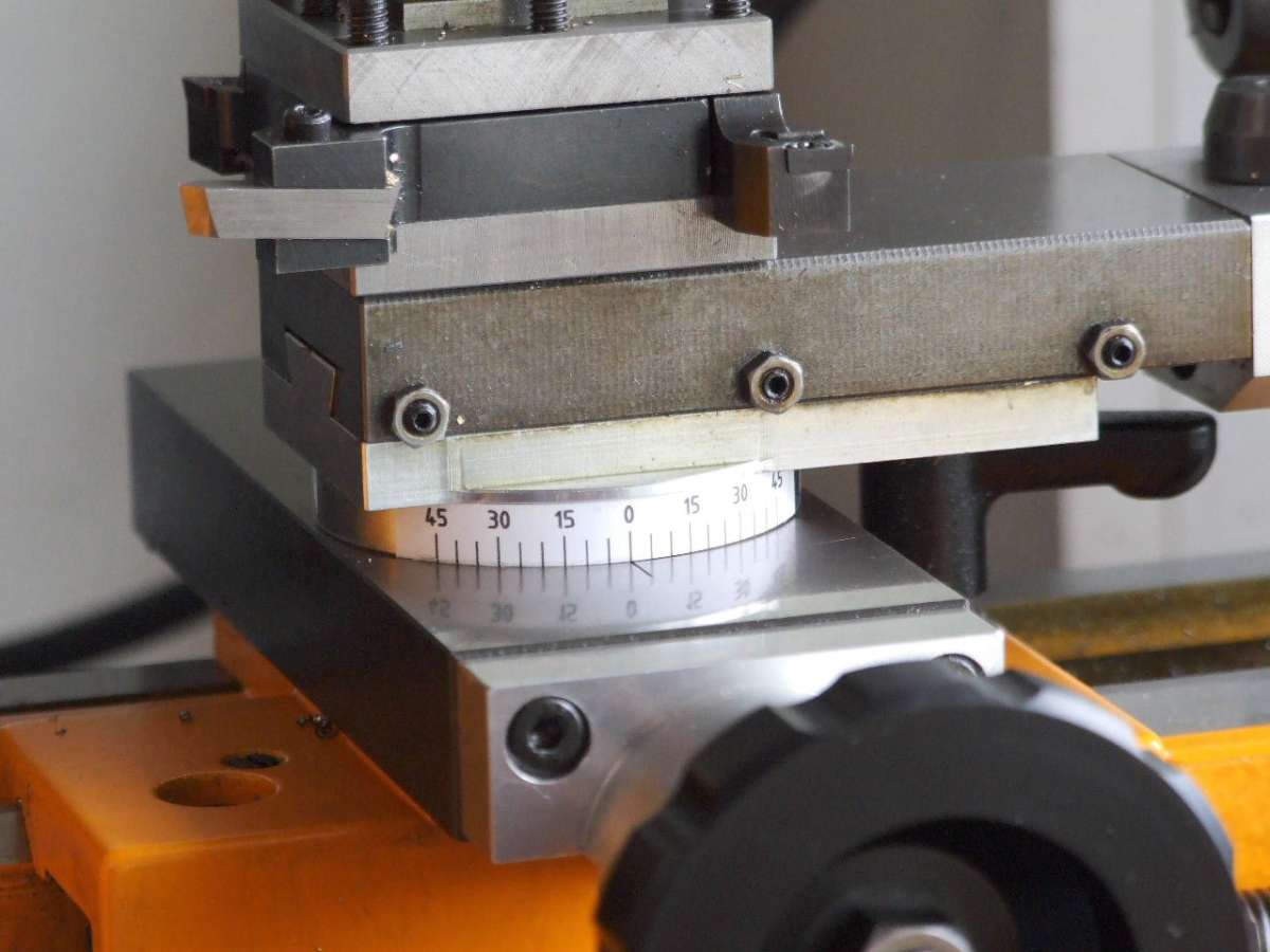
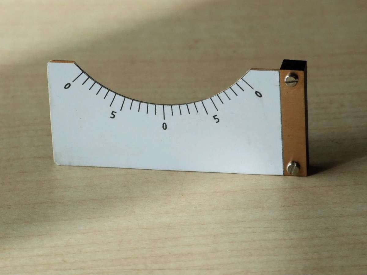
This was made such that it could removed when not needed. The time also seemed ripe to add some Vernier scales to this new scale. The outer “0” either side of the main “0”, or Zero degrees, represents the 45 degrees either side of Zero. The “5” graduations represent 1 degree of movement when used in conjunction with the top-slide scale. This is a vast improvement over the original Emco scale which was 5 degrees per division.

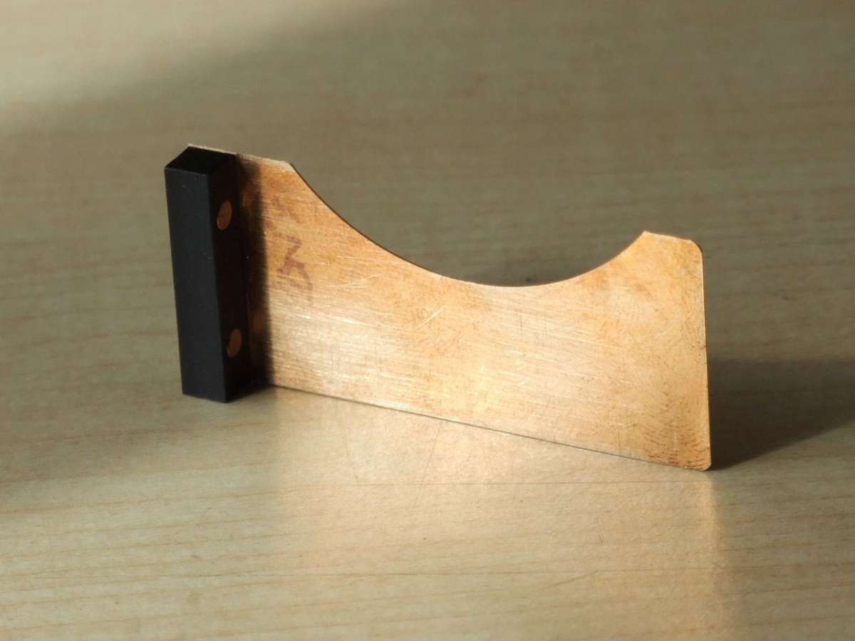
The cross-slide scale is supported on a piece of 0.2 thick Phos Bronze sheet. The two magnets ensure the registration of the scale and that it stays put when adjusting the topslide.

This last picture shows the topslide set to 60 degrees. Previously this would require using an adjustable set-square off the face of the Chuck. This was always fiddly and time consuming. This time it took only as long as undoing the retaining capscrew. Turning the top-slide to 15 degrees, (Ref 45+15=60), and retightening the capscrew.
The permanence of the inkjet is good, it is not affected by Oil or Isopropyl. As regards the adhesive strength, then only time will tell on that score. I have a plan “B” in that I can give the scale a coating of clear lacquer to seal the joint if it does prove to be a problem.
One thing I have noticed from the photograph is that the scale on the top-slide base is on the skew. This will be attended to tomorrow.
My only regret is I could not replicate the White on Black scale of the original.
Regards
Gray,
14 August 2024 at 20:38 #747030Pete
Participant@pete41194Very well done as usual Gray. It may not be the same as the OEM white on black, but to my eyes that looks much easier to read, and no doubt a lot more accurate with the removable vernier scale. I never would have thought of doing it that way. Very logical after I’ve seen it done. No doubt Emco had there reasons and likely just due to the lack of room, but the other issue on mine is having to retract the top slide a fair distance just to loosen the attachment bolt. Trying to pre set it with an indicator against a known taper is in my opinion fairly time consuming.
15 August 2024 at 12:55 #747170Graham Meek
Participant@grahammeek88282Thanks Pete for the encouragement.
At least one non-Emco user has realised that the auxiliary scale on the cross-slide will work on his Myford S7.
As regards fine tapers this is something I looked into a while back when I was considering how to make Morse tapers on the C5. The top-slide is limited in the travel department as well.
I had sketched out a Taper Turning attachment which had an auxiliary slide mounted on the back end of the cross-slide. Motion to this slide was provided by a linear ball bearing working on a hardened and ground piece of shafting. This shaft being set to the angle required.
Problems came with the proximity of the Motor to the attachment and how to attach the auxiliary slide to the cross-slide. As you know I do not like adding additional holes to my machines. In the end I just put it on the back burner as I thought the demand for such a device would be very limited.
I have two more attachments to come and that will conclude my C5 Mods, but they will take a while to make.
Regards
Gray.
15 August 2024 at 20:45 #747272Pete
Participant@pete41194I’d guess there’s really not that many that still have one of these lathes Gray, so that would be why your not getting a lot of response or feed back. I’ve never owned and am unlikely to ever have a Super 7. I still have many books about them including GHT’s excellent designs and writing. Almost any of this can generally be adapted, modified or used for other brands of equipment, just like your very clever vernier scale example.
And I think with what I’ve seen with my own C5 lathe, they can be “tuned” to be a fairly accurate lathe with a bit of thought and effort Gray. Fwiw, maybe I should add the following as some extra food for thought. Money was a bit tight when I bought my C5, and I had to add almost all of the Emco accessories built for it as I could afford them. One of the cheapest and something I was at the time completely unsure of as to there actual benefit were what Emco called leveling elements for the C5. But I always got a sometimes variable amount of easily measurable longitudinal taper on any longer parts or bores, so I bought them.
What Emco came up with is a pair of separate plates about 1/4″ / 6mm thick extending out maybe an 1″-1 1/2″ / 25 – 38mm in both directions past the front and rear of each lathe bed support foot. The bottom plate is rigidly bolted to the bench top. My lathe isn’t currently handy right now, so some of my dimensions are guessed at or approximate. Each top plate is drilled and tapped for O.D. threaded nuts below there fairly short hex heads. Those nut O.D. threads would be around 9/16″ – 5/8″ for there major diameter, although mine are metric for threads and dimensions, and for obvious reasons, are a fine pitch thread. The bottom plate was tapped for metric threads, but I re-drilled and tapped for 1/4″ diameter X 28 tpi cap screws directly below those hollow nut threads. And then slightly enlarged the through holes in those hollow nuts for my barely larger imperial bolts. Both top plates are also rigidly attached to the bottom of each of the lathe bed support feet using the OEM slots and bolt holes at each end of the bed. During any adjustments, the cap screws going through those hollow nuts are loosened and then the nuts are very slightly adjusted up or down depending on which end of the bed your working at, and the direction of the longitudinal taper. The cap screws are then tightened and used to pull the lathe down and against the ends of those adjustment nuts, and also lock those adjustments. But as belt and suspenders, I’ve still added proper lock washers under the cap screw heads just in case. I doubt those do much other than make me think they might. But it all works extremely well. These plates and how there adjusted are still in my opinion a very clever and simple solution that seem to be rarely mentioned. Scaling the idea up would work for any larger and heavier lathe. For mine, and once I finally bought one, I do use a machinist level to get the head stock end dead level across the bed ways. After that, the only adjustments I do are then and only at the tail stock. The lathe beds exact degree of level at that end is unimportant since I’m then trying to adjust the bed to produce a parallel turning condition. And those adjustments are done and also help correct or compensate for the minor deflections that happen throughout the whole lathe during actual cutting conditions. Even some amount of wear on the bed could be adjusted for if it’s not excessive. That perfectly level is only a static condition, but it does at least get you to a fairly close starting point.
My C5 back then was bolted to a pretty heavy 1 1/2″ thick MDF bench top and work bench that weighed at least 500 lbs. After adding those leveling plates, it definitely showed some real promise and mostly solved the tapered parts issues. I still thought the lathe might not be performing as well as it could. Around that time I ran across a forum post mentioning that a lot of people with home shops were doing small batch production parts in North America during WW II. That much I do know is true for both Canada and the U.S. So far, I haven’t been able to 100% verify the rest of the details in that post. But quite a few years ago I did see a couple of drawings somewhere online that SB had produced, so the story does have at least some partial truth to it. Finished part accuracy and the surface finish requirements were becoming a real problem during that war since too many parts were being rejected. Enough so even a few people in the U.S. war department got involved. Apparently they approached South Bend lathes and a few other of the smaller bench type lathe manufacturer’s for a relatively cheap and easy solution.
What SB came up with was a heavy 2″-3″ thick cast concrete top with internal steel reinforcements and threaded steel inserts cast into the correct locations to accept the lathes mounting bolts. It was the added weight and rigidity directly bolted to the lathe bed itself that made the difference. So I used that basic theory and started looking at my C5. Instead of concrete, I bought a 1″ thick X 12″ wide and I think 27.5″ long steel plate that was the full length of the lathe and the full depth of the chip pan. I added 2 counter bored holes at each end to fasten it to the bench top, and the drilled and tapped holes for attaching the bottom leveling plates. If I recall the numbers correctly, that plate weighs a bit more than twice what a bare C5 lathe does. But in my opinion, those leveling plates and that heavy steel plate transformed what the lathe was then capable of. Noticeably better and more accurate machined parts and surface finishes. I’ve had mine adjusted to part tapers of only a few .0001″ at most over the lathes full between centers distance. In my situation, the lathes accuracy can and does change a bit due to temperature and humidity changes, but that’s a factor of the floor construction in my shop. And in my opinion, the lathe even operates much more quietly.
This is already too long, but given how Emco used what I think were almost for sure die castings for both the head and tail stock. I also suspect there’s some gains that could be had by completely filling those cavities with an epoxy / granite mix if the internal access to any of the bolts etc can be protected. Those castings are in my opinion quite thin for the job they were designed to do, and aluminum sure isn’t the best at absorbing machine tool vibrations. Seriously stiffening up those castings and the better vibration resistance that epoxy / granite mix would provide should also show some noticeable improvements. It’s only a thought I’ve had, and so far I haven’t gotten any more serious about it than the thinking part.
16 August 2024 at 16:32 #747381Graham Meek
Participant@grahammeek88282Thanks for the Info Pete.
I have found the original levelling element instructions that came with my lathe.

I have included this above for those wishing to do something similar.

For my part I chose to permanently mount two steel blocks to the base of the lathe. Each block rests on two M8 Allen Grub screws accessed from beneath the Kitchen counter top offcut. The Grub screws work in M8 “Screwcerts”. These screw into the counter top from above. Centrally between the two M8 Grub screws is an M8 stud. This is permanently fixed in the steel blocks. The outer end beneath the counter carries a large custom made thick steel washer about 30 mm diameter and 8 mm thick, plus an M8 Nut. Adjustment or Levelling of the machine generally follows the above procedure. When all is complete the M8 nuts are tightened and the lathe again checked for truth.
The Unit holding the counter top is anchored to the wall and as such is not influenced by the seasonal adjustments Mother Nature carries out to the concrete floor.
If I were starting again I would probably use a pressed Concrete Slab to mount my lathe on. These can be cut to suit at the local builders merchants.
Regards
Gray,
16 August 2024 at 21:58 #747416Pete
Participant@pete41194Many thanks for adding those Emco instructions Gray. Much better than my guessed at size estimates and description.
19 August 2024 at 12:07 #747904Jamie Wood
Participant@jamiewood67138That’s a nice solution with the vernier scale Gray. I may have to give that one a go the next time I need the topslide back on the C5. I assume your scale would also work with the original Emco angle markings?
19 August 2024 at 13:40 #747923Graham Meek
Participant@grahammeek88282Hi Jamie,
It is nice to hear from you.
You are quite right about the Vernier scale working with the Original Emco Scale on the Top-slide. This Vernier was something I had intended doing for some time. My original idea was to engrave the Cross-slide at 45 degrees either side of Zero, but somehow I never seemed to get around to it. Then when the original scale was damaged the Grey matter kicked in and came up with a much simpler solution.
I am currently waiting for a reply form a Company who say they can do my new 45-0-45 scale in Black on White to match the original Emco scale.
My best regards
Gray,
19 August 2024 at 15:24 #747940Jamie Wood
Participant@jamiewood67138Hi Gray, yes I haven’t really got back into this forum much since the whole system changed, but I have just started getting notifications from this Emco thread of yours. Glad to see your modifications are continuing nicely.
I was thinking about the colours acutally. Could you not just invert your artwork colours and print the negative black onto your white vinyl? Depending on your printer the block of black may not look quite as good as somone who can print white ink onto black but probably a lot quicker/cheaper. I can help with inverting the colours if you need, just send me a pdf or image of the artwork and I can alter it.
Jamie
19 August 2024 at 16:35 #747950Graham Meek
Participant@grahammeek88282Thanks for the offer Jamie.
I have sent you an email. As it would be nice to have my own printable version just in case any Forum member should need it in the future.
Regards
Gray,
26 August 2024 at 16:21 #749003Graham Meek
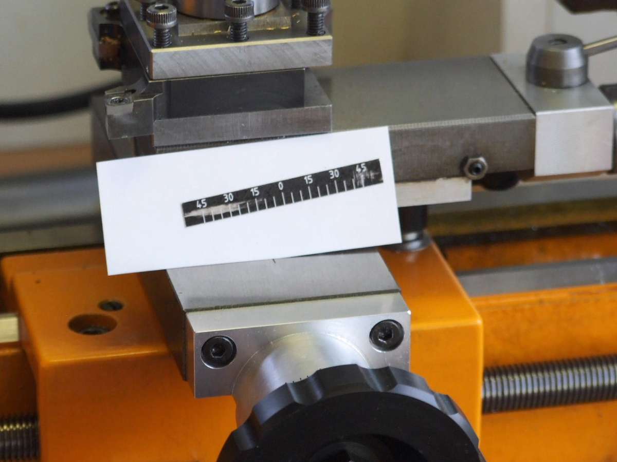
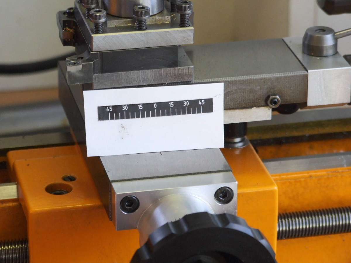
Participant@grahammeek88282Thanks to Jamie I now have a White on Black Scale. The path to this scale was not so easy as my Qcad produces the PDF at 93% of the original Artwork, but with a bit of skull duggery I finally got there.

The photograph above shows Gloss Vinyl with and over spray of Clear Lacquer.

Above shows that the Gloss Vinyl is not durable enough without the clear lacquer coat. The long mark was the artists paint brush that I was using to smooth the scale. The other marks are from the tweezers used to hold the scale.

The Matt Vinyl is shown above. While this is more durable, the Black is more of a very dark Grey. The photograph does not do justice to the difference. I did think the Matt Vinyl would be better for accepting the clear lacquer, but the finish was not as good as the lacquer on glossy vinyl.
Regards
Gray,
3 October 2024 at 17:35 #757242Graham Meek
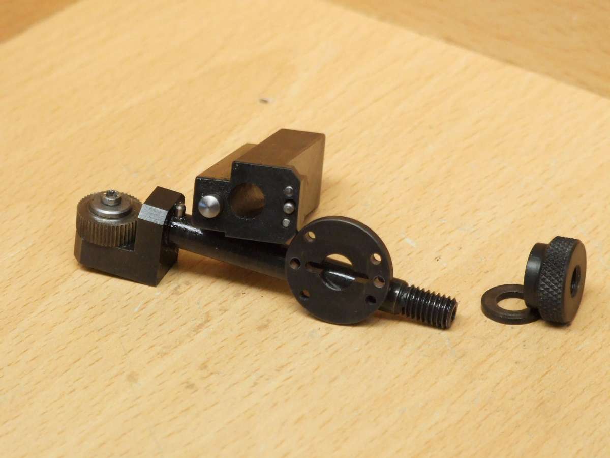
Participant@grahammeek88282Whilst this is not really a modification to the Compact 5 it is none the less a very useful addition.
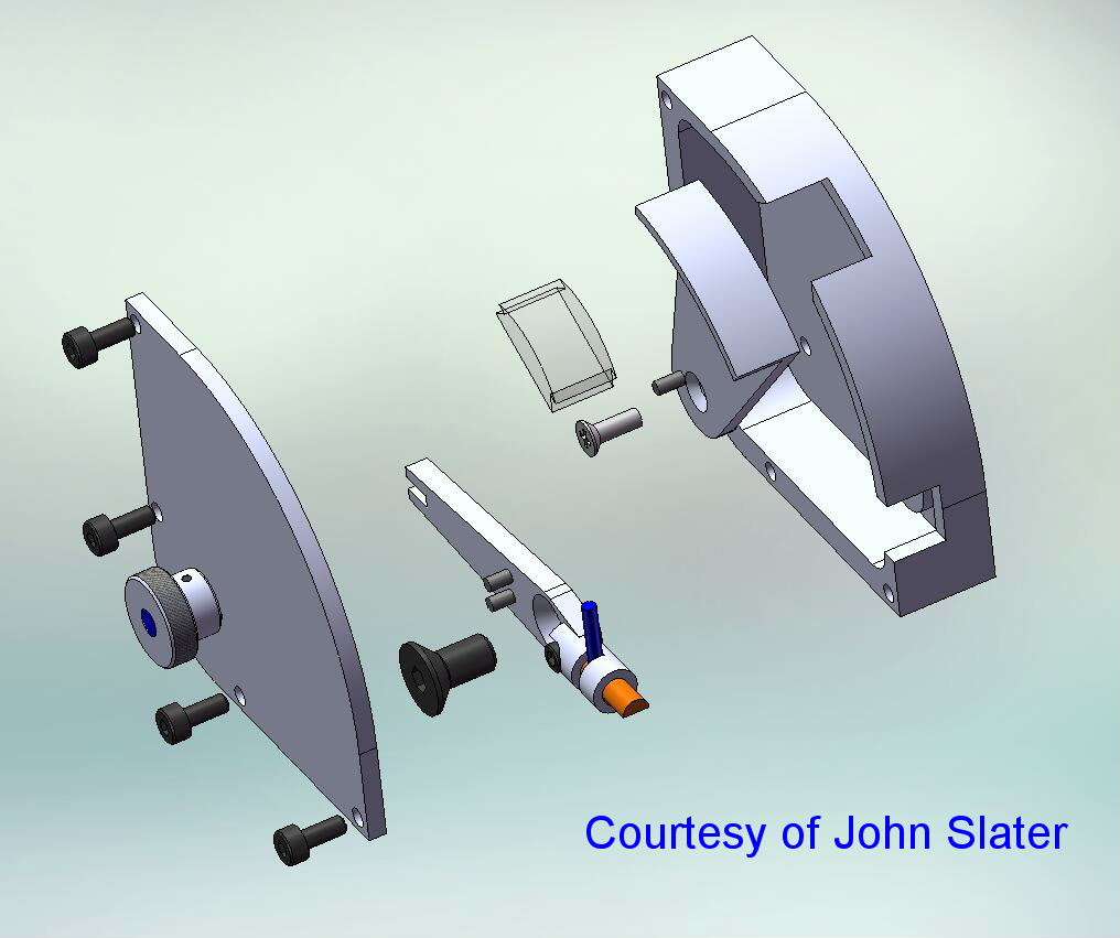
I was recently saying to John (Slater), that I was about to start making a scaled down twin wheel Knurling tool. Similar to the one I had designed for my Maximat many years ago. By way of giving me a Rabbit Hole to disappear down, John sent me some photographs of his Cut Knurling Tool. Once I was in the Warren he sent me further information and a design by Jacques Maurel got my attention.

And,

The upshot of this is a tool designed for the Compact 5 which produces some excellent knurls without even trying.

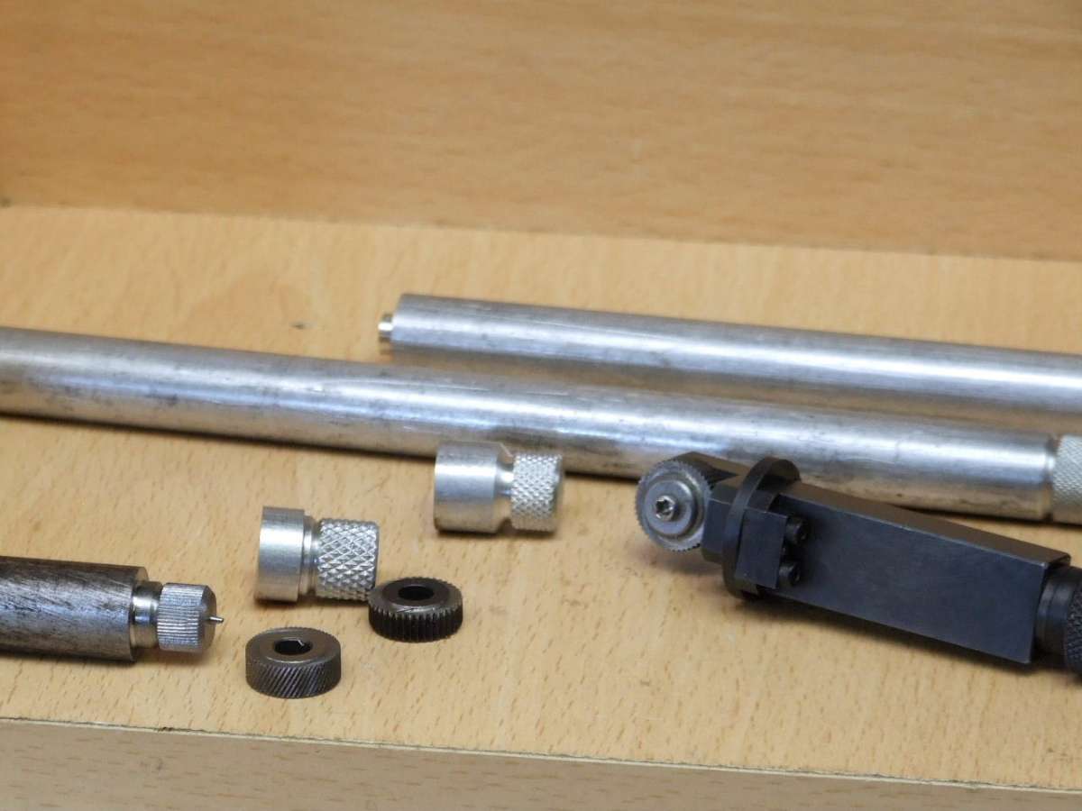
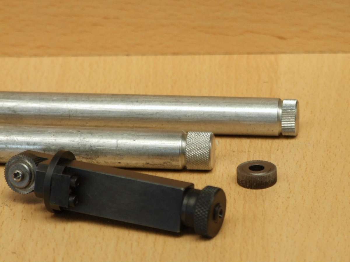
The parts of the knurling tool are shown above. A sample of the knurling produced can be seen on the Knob which holds everything together in the assembly. The Index plate gives square knurls as well as the regular diamond knurl. To keep things together when changing from position 1 to position 2 I have included a spring loaded plunger. This pushes the plate and the knurling head away from the adjustable Indexing pin. (Held by the small block and the two Cap screws.)
Releasing the Knob further allows the plate to slide off the Snug in the Wheel head and to be rotated to allow square knurls to be produced.
I will post some further samples of the work produced as well as the trails and tribulations on my attempt to do straight knurling with this tool using helical knurls.
I will just finish for now with a thanks to John for the Rabbit hole, and to Jacques for an elegant design.
Regards
Gray,
3 October 2024 at 21:59 #757278Colin Creed
Participant@colincreed93792Hi Graham,
That looks to be a terrific asset for our smaller sized Lathes.
I’d seen one on YouTube being made by a young guy for use on his Chinese Mini Lathe & since then, had pondered what were the “true” details involved with making one.
Looking forward to seeing & hearing more about this.
regards Colin
4 October 2024 at 00:27 #757311Pete
Participant@pete41194As always, lovely work and design Gray.
Fwiw the HSM magazine had a very good article some years ago about shop building your own cut knurling tool. Very similar style and as good as G. Thomas and of course Gray’s. Mine’s not handy or I’d give the dates and issues it was in, but an online search should turn that up.
4 October 2024 at 11:46 #757354Graham Meek
Participant@grahammeek88282Thanks Colin and Pete for the kind comments.
One of the Rabbit Warren holes was the article from HSM, so I already have that.
I first saw Cut knurling being done at the Machine Tool Exhibition in Birmingham in the 80’s. While I would have liked such a tool the cost of the tool was greater than a new GripTru Chuck for the Myford. Plus the shank size was too big for the S7. Even clamping it to the topslide.
I forgot to mention yesterday that the knurling wheel is canted over at 3 degrees so that the corner of the knurling wheel is presented to the work. The face of the knurling wheel has been dished by 3 degrees. This is to ensure a sharp corner on the knurling wheel and to give a neutral cutting angle. If it had been left unground then there would have been a negative rake angle presented to the work.
Here are a few examples of what I have done so far, the main objective was to produce the diamond knurl for the Knurling Tool.

The above shows some close ups of the knurls produced, please ignore the straight knurl I am not impressed with this.

The Straight knurl on the aluminium bar was produced using the straight knurling wheel vertical. This still cut the knurl, rather than forming it, but I found it needed several passes to achieve the full depth.

This type of knurling is a lot kinder to the C5. I know because I have already done straight knurling for my Dividing attachment using a conventional forming process.
I think the Straight knurl in steel above is due to my approach, having received advice from John this morning. The other straight knurls that I have done using helical knurling wheels canted over in brass and aluminium, which I have yet to photograph. These are not very good and I am convinced this is because of the size of the wheels I am using and the coarseness of those wheels. The knurl faces or slopes appear to be undercut, or concave. This I feel is a product of the geometry and the size of the wheel, (1/2″ diameter). Some Macro photos I hope will shed light on this.
Regards
Gray,
4 October 2024 at 18:40 #757386v12man
Participant@v12manHi Gray and everyone – my first post on this forum.
I recently came across a site that has configurable and printable scaled rules and protractors – as well as pipe notching templates (which was what I was originally looking for) and which has proven useful as my recently acquired Compact 5 is missing some scale dials on the handwheels – I just configured a couple and printed them out and stuck them on temporarily.
I think you will be able to create the protractor needed quite easily (because there are several variants of the calculator) – and it has the ability to produce a vernier scale as well on the protractor
https://www.blocklayer.com/protractor-printeng
Hope it helps someone
Guy
4 October 2024 at 20:37 #757440Pete
Participant@pete41194Since I’ve never used a cut knurling tool yet, I guess I can only repeat what I’ve read about it from various sources. It’s my understanding that the process exerts and requires far less force due to it’s cutting action verses the mostly high pressure and extrusion forming of a more conventional knurling method. So exactly what would help the most with our smaller lathes. And it was that HSM article Gray that started my interest in it. I believe there are industrial level, fairly expensive and specific cut knurling wheels available. Likely there designed around and would probably only work on those expensive cut knurling tools you also mentioned. I suspect that unless the tool your making for yourself matched the exact same angles those commercial versions have, those cut knurling wheels may not work as intended. The geometry and wheel angles used with those tools seems to be a bit more complex than it appears. But the diamond knurling in your second photo does look very well done, so I’d call it a real success.
I bought an Eagle Rock compression knurling tool, but only use it on my 11″ swing lathe. It’s tool shank size would be far too large for my own Compact 5, and I think the forces required are more than enough I’d not want to abuse any smaller lathe like that. So what you’ve come up with Gray solves all the issues. G. Thomas did I think a very good article about diamond, straight and even square knurling. Since I don’t have any wheels for straight knurling, I do it the very slow way and use a dividing head or my rotary table and mill each individual groove with a tapered blade type cutting tool. It works, but you have to really want that type of knurling to justify all the extra set up and time involved.
-
AuthorPosts
- Please log in to reply to this topic. Registering is free and easy using the links on the menu at the top of this page.
Latest Replies
Home › Forums › Manual machine tools › Topics
-
- Topic
- Voices
- Posts
- Last Post
-
-
IME Watchmakers lathe
Started by:
Greensands in: Manual machine tools
- 10
- 15
-
1 July 2025 at 21:27
 Michael Gilligan
-
Motor won’t start
Started by:
Rowan Sylvester-Bradley in: Beginners questions
- 5
- 5
-
1 July 2025 at 21:13
Paul Kemp
-
Request for a Slot to be Milled in a Shaft
Started by:
James Alford in: Help and Assistance! (Offered or Wanted)
- 9
- 18
-
1 July 2025 at 21:03
bernard towers
-
Bearing boxes for ball race
Started by:
Paul McDonough in: Beginners questions
- 9
- 17
-
1 July 2025 at 21:02
Paul McDonough
-
Speed camera
Started by:
 David George 1
in: The Tea Room
- 10
- 11
-
1 July 2025 at 21:01
Georgineer
-
J&S grinder – belt which way ?
Started by:
gerry madden in: Manual machine tools
- 4
- 5
-
1 July 2025 at 20:56
Chris Gunn
-
Twin Engineering’s heavy mill/drill quill removal
Started by:
Martin of Wick in: Manual machine tools
- 7
- 9
-
1 July 2025 at 20:51
Martin of Wick
-
The Stevenson Trophy – Entries Invited
Started by:
 Neil Wyatt
in: Website Announcements
- 1
- 2
-
1 July 2025 at 18:44
 Neil Wyatt
-
The Bradford Cup – Nominations Wanted
Started by:
 Neil Wyatt
in: Website Announcements
- 1
- 2
-
1 July 2025 at 18:41
 Neil Wyatt
-
FreeCAD v1.0 tutorials
1
2
3
Started by:
 Michael Gilligan
in: CAD – Technical drawing & design
- 12
- 54
-
1 July 2025 at 18:31
Speedy Builder5
-
Haining vertical dairy engine boiler.
Started by:
apprentice in: Beginners questions
- 2
- 2
-
1 July 2025 at 18:26
 JasonB
-
All things Beaver Mill
1
2
…
8
9
Started by:
Robert James 3 in: Manual machine tools
- 43
- 208
-
1 July 2025 at 18:22
Charles Lamont
-
Dial test indicator vs Dial indicator
Started by:
martian in: Workshop Tools and Tooling
- 17
- 24
-
1 July 2025 at 16:59
Clive Foster
-
Meddings MF4 Manual
Started by:
Richard Kirkman 1 in: Help and Assistance! (Offered or Wanted)
- 10
- 18
-
1 July 2025 at 16:38
Howard Lewis
-
Help for DIY lathe build.
1
2
Started by:
moogie in: Help and Assistance! (Offered or Wanted)
- 16
- 32
-
1 July 2025 at 15:21
David Senior
-
Firth Valve Gear
Started by:
Andy Stopford in: Traction engines
- 9
- 18
-
1 July 2025 at 12:59
Nigel Graham 2
-
M type top slide conversion??
Started by:
jimmyjaffa in: Beginners questions
- 7
- 11
-
1 July 2025 at 11:35
 David George 1
-
Offen screw type telescopic gauge.
Started by:
Graeme Seed in: Workshop Tools and Tooling
- 4
- 9
-
1 July 2025 at 10:41
Graeme Seed
-
2 Machine lights
Started by:
modeng2000 in: Workshop Tools and Tooling
- 2
- 6
-
1 July 2025 at 08:57
Dalboy
-
New member looking for help
Started by:
 manfromthemist
in: Introduce Yourself – New members start here!
- 11
- 24
-
1 July 2025 at 08:19
Juddy
-
Wiring up a single phase AC motor with 4 wires
Started by:
ell81 in: Beginners questions
- 6
- 8
-
30 June 2025 at 19:49
Howard Lewis
-
New (old!) member
Started by:
iansoady in: Introduce Yourself – New members start here!
- 3
- 3
-
30 June 2025 at 19:30
Howard Lewis
-
Boiler Design – issue 4765
1
2
…
7
8
Started by:
Charles Lamont in: Model Engineer & Workshop
- 26
- 178
-
30 June 2025 at 12:58
Paul Kemp
-
High strength 4mm steel?
1
2
Started by:
iansoady in: Materials
- 20
- 31
-
30 June 2025 at 10:55
JohnF
-
What Did You Do Today 2025
1
2
…
6
7
Started by:
 JasonB
in: The Tea Room
- 32
- 172
-
30 June 2025 at 07:37
Diogenes
-
IME Watchmakers lathe
-
Latest Issue
Newsletter Sign-up
Latest Replies
- IME Watchmakers lathe
- Motor won’t start
- Request for a Slot to be Milled in a Shaft
- Bearing boxes for ball race
- Speed camera
- J&S grinder – belt which way ?
- Twin Engineering’s heavy mill/drill quill removal
- The Stevenson Trophy – Entries Invited
- The Bradford Cup – Nominations Wanted
- FreeCAD v1.0 tutorials


