Emco Compact 5 Modifications

Advert

Emco Compact 5 Modifications

Home Forums Manual machine tools Emco Compact 5 Modifications

Viewing 25 posts - 51 through 75 (of 105 total)
  • Author
    Posts
  • #642182
    Colin Creed
    Participant
      @colincreed93792

      Hi Graham,

      That's another set of terrific modifications you've done,

      I'm curious to know if you'd ever considered back-filling the inner voids within the Tailstock body with something like a metallised epoxy (JB Weld, Devcon, etc)..?

      As you'd likely know, my Proxxon PD 250/E has so many similarities to your C5, its Tailstock design & construction being just one.

      In use with the 10mm Rohm Chuck, my Tailstock is "nose-heavy" when sliding it along the bed until it's locked down & so I'd contemplated about "adding weight" into the rear cavity portions..?

      Now having almost completed building your "Lever Action" attachment for my own Tailstock, I'm again wondering if filling those rear voids might help?

      Would appreciate your thoughts on whether it's a good or bad idea?

      regards Colin

      Advert
      #642229
      Graham Meek
      Participant
        @grahammeek88282

        Hi Colin,

        Thanks for the kind comments as regards the design.

        I have never considered the need for the void filling. Plus with the C5 tailstock, access is required from below to get to the two set-screws used to locate the tailstock barrel and lock the feedscrew bearing.

        The design of this attachment will not allow the tailstock to droop when you move it. The lever action allows just enough clearance for the tailstock to slide when released. It is a bit like just slackening off the clamping plate on the standard set-up to allow the tailstock to slide. Unfortunately using the standard set up to do this usually results in the clamping plate jamming, due to the turning moment on the plate.

        It is funny but this design actually came about because of a YouTube video on converting a Proxxon Tailstock to lever clamping. This involved machining the tailstock body, (a big No-No with me, which I have proved is not needed). Which combined with the sloping back face on the tailstock of that particular model and the oversize bore used. I considered not to be a real proposition on the C5 especially as the two internal ribs which take the camping forces would be virtually machined away.

        The beauty of this design in use is that I can release the locking lever with the third finger of my Rt hand. Move the tailstock with my thumb, index finger and second finger, then re-lock again using the third finger. One slick operation which makes using the machine so much more enjoyable. Plus makes me more efficient in my work time. (By the way the lever ratio is 30:1)

        At first glance I can see no reason why this type of attachment would not fit these lathes, and I had considered mentioning this in the previous post. Of course I would really need to have access to a machine, or machines in order to make a proper appraisal.

        Regards

        Gray,

        #650212
        David Russell 1
        Participant
          @davidrussell1

          Hi Graham,

          Recently acquired an abused Emco Compact 5 and readying through the forum posts for rebuild/upgrade references. I noticed that you have 3 different C5 tailstock photographs within this forum thread: original, lever added, and machined base with lateral keyway and lever. Would you mind sharing more information on the tailstock with the lateral keyway? It is shown 2 posts above.

          Best Regards,

          David

          P.S. 2 C5 milling heads are current for sale on eBay here in the USA

          #650364
          Graham Meek
          Participant
            @grahammeek88282

            Hi David,

            I my apologies for not replying sooner. I have been in the middle of a Broadband upgrade that did not go too smoothly.

            my c5 lever clamping tailstock.jpg

            I take it this is the tailstock base you are referring to.

            This was a salvage scheme done many years ago when I first had this machine. This was a tailstock from a donor machine. The original tailstock was out and rocked about on the bedways. The salvage of this tailstock on my Proxxon mill appears earlier in this post.

            The Donor tailstock body was modified because the tailstock barrel was running out towards the back of the machine. Plus it was also dipping down towards the bedways.

            I have been intending to draw this up and write an article on how to do it. The problem there is it may be some months before the article will get published. This modification is not for the faint hearted it requires a good deal of patience to achieve the desired effect. It does combine an adjustment to ensure the tailstock centre-line is coincidental with lathe spindle.

            If you will bear with me and maybe give me a nudge via a PM in about a months time I will see what I can do.

            Regards

            Gray,


            Edited By Graham Meek on 29/06/2023 15:38:54

            #653016
            Graham Meek
            Participant
              @grahammeek88282

              Base Salvage scheme

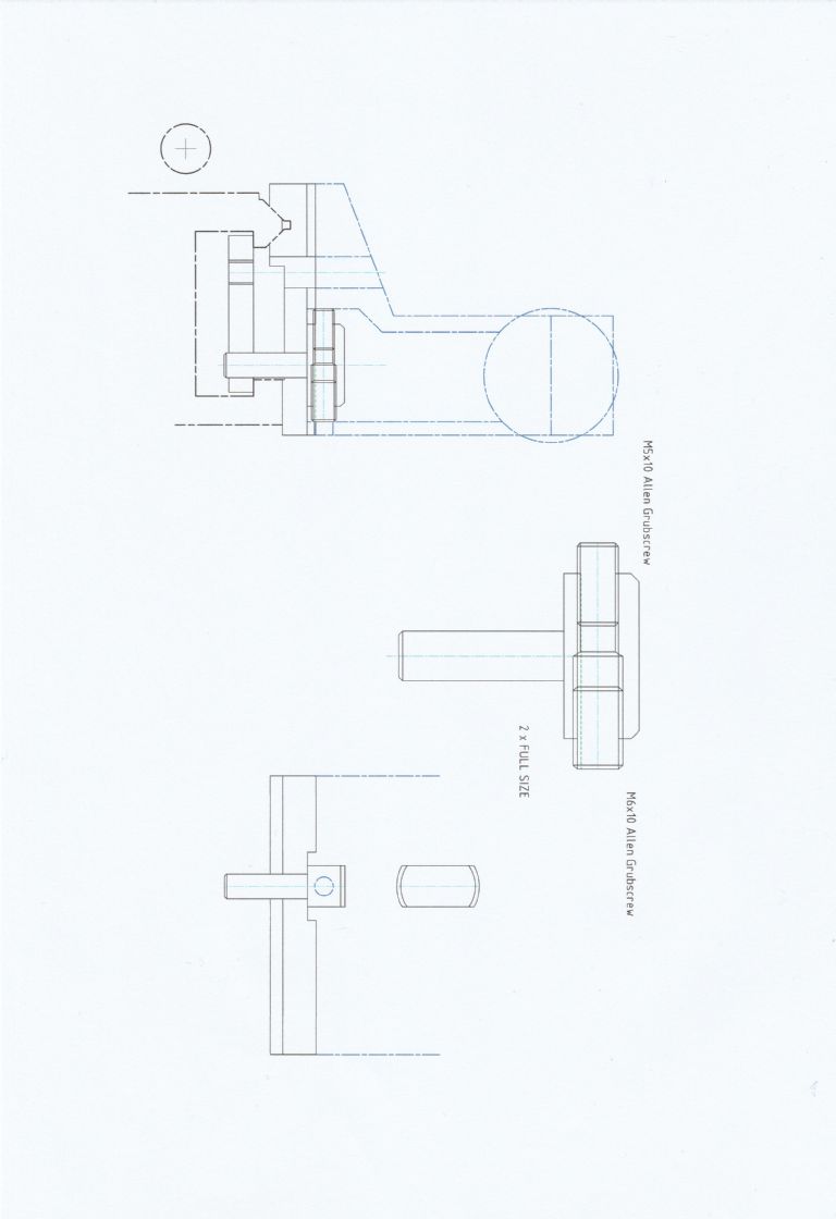
              As promised I have made a start on the Tailstock Base Salvage scheme, as used on my own C5.

              Unfortunately during uploading to this site the drawing has turned through 90 degrees.

              The scheme incorporates a means of moving the tailstock laterally across the bedways. This involves one M5 grubscrew being in contact with the inside wall of the tailstock casting nearest the M6 Clamping screw. While an M6 grubscrew impinges on the rear inside wall of the casting.

              Access to this adjustment is via a hole which Emco kindly provide in the back of the casting. Unfortunately this hole is in two different places on the tailstocks that I have. The newer casting has the hole lower down as shown. To accommodate the casting with the hole higher up just requires making the head of the spigot taller.

              This spigot also locates the clamping plate, (which needs to be modified with a 6 mm hole), and stops this plate from jamming when moving the tailstock. The addition of a spring around the M6 clamping screw between the plate and the the new tailstock base, further refines this set-up.

              The M6 grubscrew is drilled though to allow a 2.5 mm A/F Allen key access to the M5 grubscrew. This moves the tailstock towards the operator while the M6 grubscrew moves the tailstock away form the operator.

              Once the optimum setting is reached the two grubscrews lock the casting to the new base plate due to the opposing forces of the grubscrews. This however does not want to be overdone as there is a risk of breaking the rear tailstock casting wall.

              I have yet to dimension the drawings which I hope to complete over this weekend.

              Regards

              Gray,

              #653254
              Graham Meek
              Participant
                @grahammeek88282

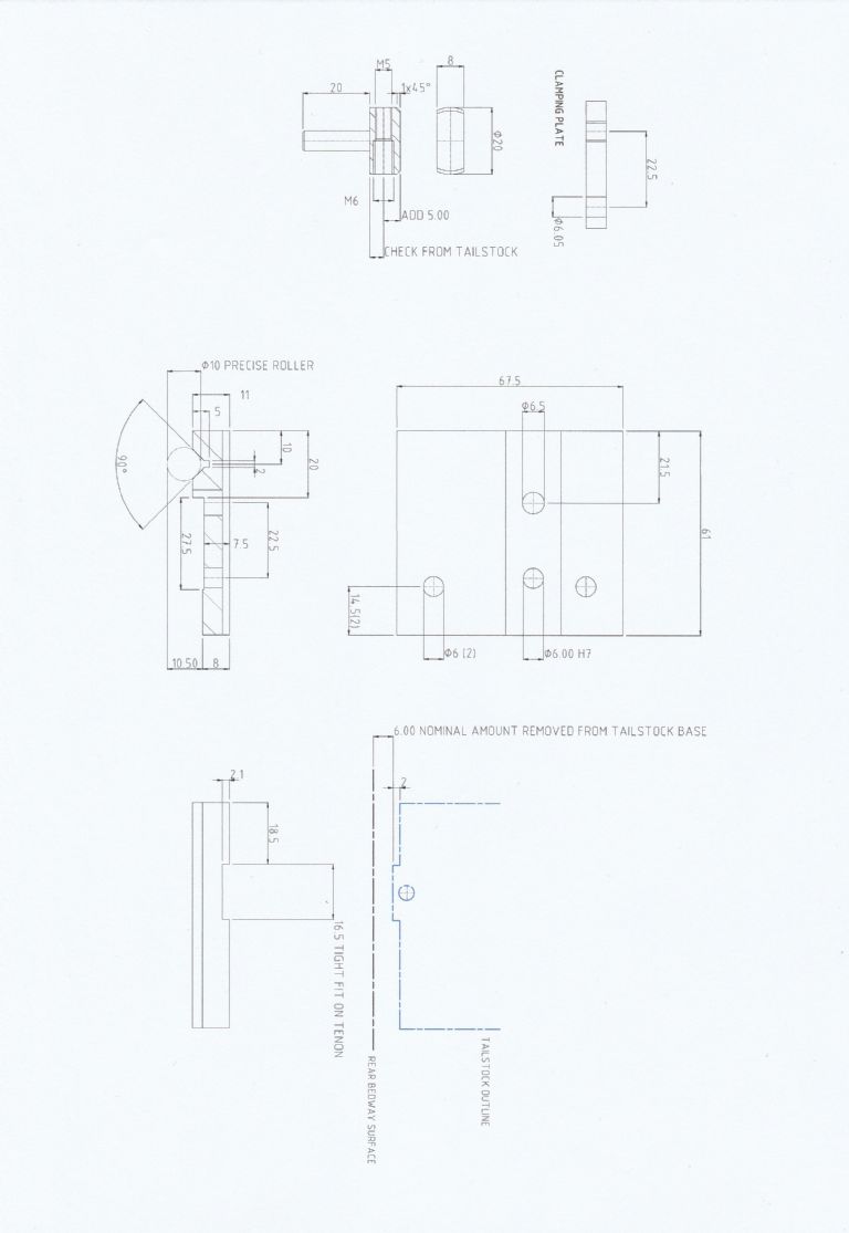
                compact 5 tailstock  base salvage.jpg

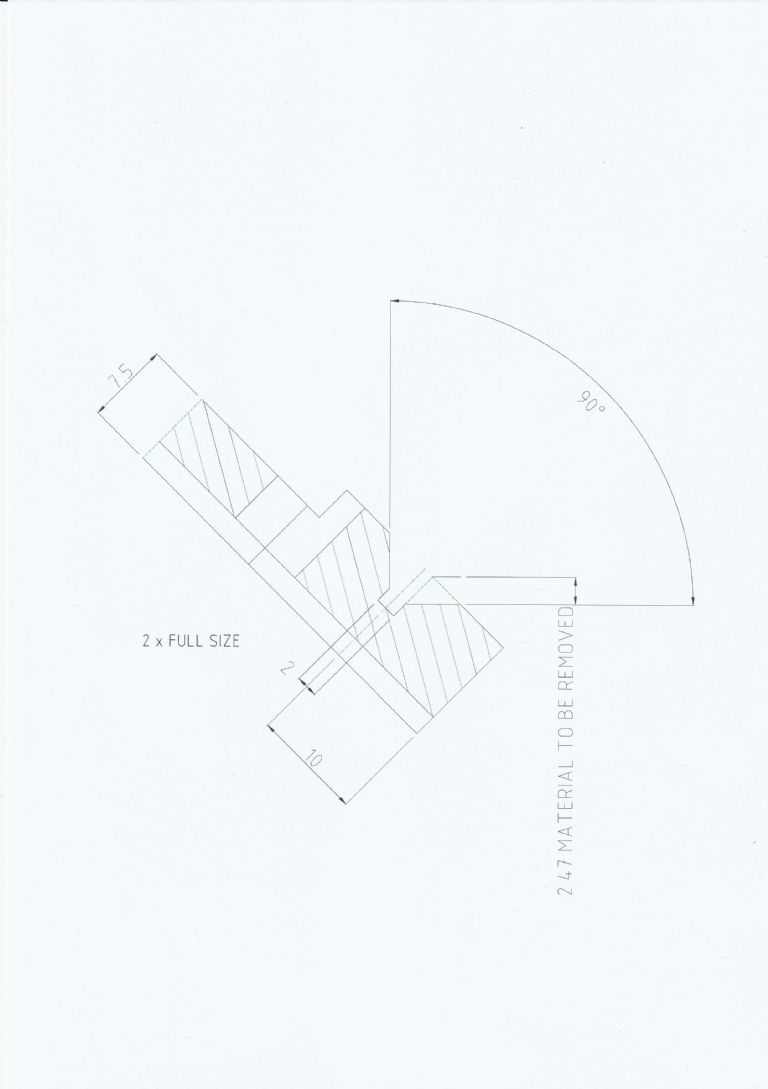
                Here are the drawings of the modification. As I said earlier this is not something for the faint hearted. It is easy to achieve provided the project is approached methodically. To make the New base I would recommend using a jig which is machined in situ in the dividing head, with tailstock support. A tenon machined on the jig will automatically orientate the base to ensure alignment. The base can be held on the jig using the two 6 mm diameter access holes for the grubscrew which locks the tailstock feedscrew bearing and the Dog point Barrel alignment grubscrew. M5 tapped holes will be more than adequate.

                Rotating the dividing head will ensure a perfect 90 degrees for the Vee. Provided the bottom of the Endmill or slot drill is used. Once the Vee is established the 10.50 mm dimension can be established. This also ensures all surfaces run parallel to one another.

                It would pay to leave the base oversize on thickness, say about 0.1 mm to allow for some fine tuning once all the parts are made. It is always better to have material to come off than having to put some back on or even starting again.

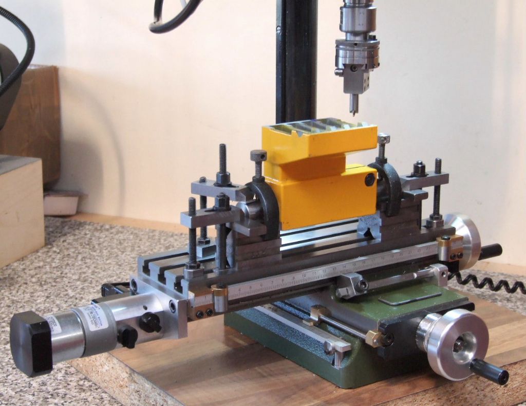
                tailstock on mill.jpg

                To machine the tailstock a set up as used earlier in the post using two Vee blocks and a mandrel will ensure the alignment of the tailstock barrel bore and the Tenon.

                Regards

                Gray,

                #653370
                Graham Meek
                Participant
                  @grahammeek88282

                  I have added an additional view for those who want to make this conversion. It relates to the amount of material that needs to be removed from each side of the Vee. Please note this only applies to a 2 mm wide slot. If the slot is less or more than this then some trig will work out the different dimension.

                  c5 base.jpg

                  Regards

                  Gray,

                  #707866
                  Graham Meek
                  Participant
                    @grahammeek88282

                    It has been a while since I posted anything new on this thread having just completed a revised Cross-slide feedscrew bracket for the C5. I thought I would brave the new forum and see how it goes.

                    feed screw assy


                    I have incorporated a locking mechanism to make adjusting the dial easier. The new slightly longer bracket now has a Vernier scale to allow 0.01 mm sub-divisions of the 0.05 mm main dial graduations.

                    Vernier Scale on revised Bracket

                    The new screw cut feedscrew has made the feed much smoother in operation and the lock is more than capable of holding the feedscrew during alterations to the dial.

                    Side View showing Thumbscrew Lock

                    The Vernier scale was cut using the 40:1 dividing attachment I made for the standard C5 Dividing attachment. The Vernier needed a new 50 hole indexing plate. As the scale needs 62.5 divisions in total, which is not easy, but doubling this we get 125 divisions. Which is 16 holes on a 50 circle. Thus by setting the sector arms to cover 32 holes on the 50 circle we get our 62.5 divisions.

                    Test cuts have shown that it works and I am more than pleased with the addition, despite the cold workshop.

                    Regards

                    Gray

                    #708198
                    Jouke van der Veen
                    Participant
                      @joukevanderveen72935

                      Hallo Gray,

                      Nice piece of work!

                      Did you do all the machine for this modification on the C5 and your Proxxon mill?

                      Regards,
                      Jouke

                      #708226
                      Graham Meek
                      Participant
                        @grahammeek88282

                        Hello Jouke,

                        I thank you for your kind words.

                        You are right all the machining was carried out on my C5 and Proxxon Mill. With a little help from the Proxxon bandsaw to remove some of the waste material. The accuracy of the C5 continues to amaze me. I had less than 0.005 mm taper over the 74 mm long M8 feedscrew thread. Taking out the guesswork as regards the size of a small cut has long been on the list of priorities. At long last I have accomplished this.

                        This project did through up the need for a tailstock die holder. This was something that I had, but had to let go with my Maximat S11 lathe as it was just too big for the C5, being No 2 Morse taper. It was another thing on the “to do” list but which was totally forgot about, until it was needed. As I have the Unimat 3 as well the design for the new die holder needs to be dual purpose.

                        Regards

                        Gray,

                        #708414
                        Jouke van der Veen
                        Participant
                          @joukevanderveen72935

                          Dear Gray,


                          You designed and made so many modifications (improvements) for the C5 that you could fill a book with it I think. It would be a bestseller to the Emco Compact 5 community!

                          Regards,

                          Jouke

                          #708492
                          Graham Meek
                          Participant
                            @grahammeek88282

                            Thanks Jouke,

                            It might be a bit premature as regards a book as I still have one or two things on the drawing board for the C5.

                            I have been toying with fitting a modified feed unit similar to the one I recently designed for the Proxxon Mill. At the handwheel end of the C5 thereby giving infinite electronic fine feed selection.

                            FF 230 Table Feed attachment

                            The leadscrew on the C5 and the feedscrew on the Proxxon mill are both M12 x 1.5P so I know the sort of range of feeds I will be able to get.

                            Completing this design and the other items is a priority at the moment. However I don’t think the publishing companies share our enthusiasm for the attachments to warrant a book.

                            Regards

                            Gray,

                            #708771
                            Jouke van der Veen
                            Participant
                              @joukevanderveen72935

                              Thank you Graham,

                              I am struggling with a motorfeed on the crossslide of the C5 bed to be used as a mill crosstable. It is good to hear that you work on the leadscrew feed.

                              The idea is to fixate the crossslide screw in the (old design, without a halfnut for backlash correction) saddle and to attach a motor with a hollow axis direct to the front of the crossslide. The motor then moves along the fixated screw by means of a adjustable halfnut) in the rotating hollow axis.

                              I realize that putting all things in line will be critical. And the motor I have already is an nema23 and is rather heavy on the end of the screw when the crossslide is in the frontend position. All details have not yet been settled. Perhaps I have a picture somewhere. I did some pre-assembling.


                              #708885
                              Jouke van der Veen
                              Participant
                                @joukevanderveen72935

                                IMG_2267IMG_2260

                                #709006
                                Pete
                                Participant
                                  @pete41194

                                  Very interesting and as usual well thought out, designed and machined modifications to your C5 Gray. I did notice your still using the OEM cap screws to lock the quill and tail stock to the bed. I bought a pair of ratcheting lever handles with the same male thread pitch Emco used. Less than 5 minutes to replace both and extremely nice to not have to hunt for the correct sized wrench ever again. The convenience far outweighs there minor cost. In the UK I seem to remember there called Bristol handles? In my opinion, Emco should have provided the same on all the C5’s.

                                  When I bought mine I always got a fairly serious taper on longitudinally turned work. Adding what Emco called there “leveling elements” to my C5 made it into as you’ve found a very accurate lathe. I’ve had mine adjusted to less than .0002″ taper in almost 12″ of 2″ diameter stainless steel bar if the cutting depths and feed rates are reduced to what the C5 is actually capable of.

                                  #709050
                                  Graham Meek
                                  Participant
                                    @grahammeek88282

                                    Hi Pete,

                                    The above picture does not show enough of the tailstock to show my set-up.

                                    My C5 Lever Clamping Tailstock


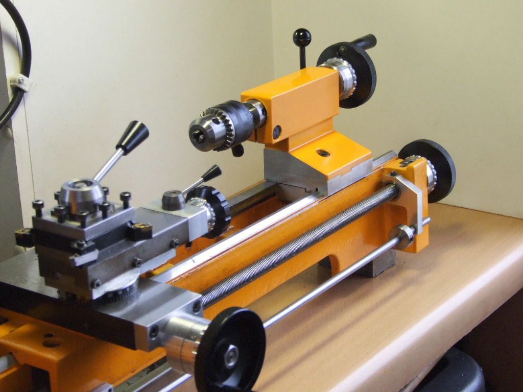
                                    The tailstock utilises the existing M6 capscrew to clamp the tailstock to the bed via the lever situated by the dial. Once the capscrew is adjusted it requires no further attention. If you look closely under the drill chuck you can see my tailstock barrel clamping lever. This is supplied by Elesa and is a parallel handle version, GN 302.1 which is not as long as the more common Kipp type levers.

                                    The only file I have will not load on this forum. I also use the same lever to lock the Bed as it is shallow enough to miss the topslide.

                                    Regards

                                    Gray,

                                    #709076
                                    Graham Meek
                                    Participant
                                      @grahammeek88282

                                      The style of lever can be seen in this M4 version that I have installed on the Proxxon Milling machine.


                                      X-Axis Attachment


                                      Regards

                                      Gray,

                                      #710086
                                      Pete
                                      Participant
                                        @pete41194

                                        Thanks for the additional pictures and details Gray. And had I studied your previous pictures a lot better, that would have been clear. I already should know you’d be well ahead of whatever I could add to your posts. 🙂 And those adjustable handles work very well on the smaller machines.

                                        #732256
                                        Graham Meek
                                        Participant
                                          @grahammeek88282

                                          A while back I said I was toying with fitting the Proxxon mill feed unit I designed on the C5. Well today I finally managed to get the bits together and give it a try.

                                          C5 Electric Power Feed


                                          This is the only photograph I had time to take today. I hope to take some more tomorrow with it actually on the lathe. Initial test have lived up to expectations and the fine feed is about half of what the standard Emco fine feed was using their feed attachment.

                                          Regards

                                          Gray,

                                          #732281
                                          Colin Creed
                                          Participant
                                            @colincreed93792

                                            Hi Graham,

                                            Great to see your posts & looking forward to seeing more on your C5 Feed attachment.

                                            regards Colin

                                            #732354
                                            Graham Meek
                                            Participant
                                              @grahammeek88282

                                              Thanks Colin for your kind comments.

                                              As promised here is a photograph of the feed unit fitted.

                                              Emco C5 Electic feed fitted JPG


                                              The large knurled knob controls the Dog clutch to engage the motor. The black Knob with the white dot controls the direction. While the black knob to the rear is the On-Off and variable feed control.

                                              I have only had chance to do some quick tests cutting 16mm diameter Brass and EN1A Pb at 550 rpm. The lathe will quite easily cope with deep cuts, but I am not sure I have the reaction time for the faster feed rates with shallower cuts.

                                              All in all I am pleased with my efforts.

                                              Regards

                                              Gray,

                                              #732374
                                              Harry Wilkes
                                              Participant
                                                @harrywilkes58467

                                                Interesting mod

                                                H

                                                #733129
                                                Graham Meek
                                                Participant
                                                  @grahammeek88282

                                                  Thanks Harry,

                                                  This mod has the advantage of being able to leave a screw cutting train set up on the quadrant. This is handy if I have several parts that require screwcutting and the parts don’t lend themselves to being re-chucked or mounted between centres.

                                                  It would also be handy for someone who has the C5 but no feed attachment.

                                                  Regards

                                                  Gray,

                                                  #736423
                                                  Graham Meek
                                                  Participant
                                                    @grahammeek88282

                                                    The latest item to be made for the Compact 5 could quite easily be adapted for any type of lathe. It does warrant a listing under “Tool Height Setting Gauge” but to be honest I have forgotten how to start a new thread on this new forum.

                                                    Since George H Thomas designed his Tool centre height gauge this has served me well for the past 40 years. Since going to a smaller lathe its use has been a bit of a trial. The size of the C5 cross slide is one issue the other being my failing vision.

                                                    Something which made my life easier and which was in keeping with the C5 was needed. Talking it over with John Slater back in January / February started a flurry of activity on the drawing board. Along with a multitude of Patents from John on Lever Operated Indicators.

                                                    Things were really simplified when John suggested using conical bearings for the pivots. These come in the shape of Carbide Insert retaining screws and I have to thank Ketan and Ian at Arc Euro Trade for their help here.

                                                    The design here was up to issue 10 before any machining had started. However it does live up to my expectations and has already made setting tools easier. One of the earlier designs had a more vertical scale which was viewed through a magnifying lens, (piece of Perspex rod). However a wooden mock-up of this version made it too big for the C5 cross slide.

                                                    Tool Height Setting Gauge


                                                    The Gauge is shown being used to set the “Half Pin” horizontal before actually setting the Gauge to Zero on this pin.

                                                    Setting Turning Tool

                                                    This second image shows a turning tool being set. The pointer is on Zero, but the camera says otherwise, (parallax).

                                                    Upside Down Boring Bar Setting

                                                    By turning the Gauge Probe through 180 degrees and Moving the Direction lever. Inverted or upside down boring bars can be set without any alteration to the original setting of the Gauge.

                                                    Probe Detail

                                                    This view shows the Probe details.

                                                    Direction Lever

                                                    While this image shows the Direction Lever.

                                                    The graduations on the scale represent 0.05 mm per division and the scale is a simple print out.

                                                    More later,

                                                    Regards

                                                    Gray,


                                                    #736535
                                                    Graham Meek
                                                    Participant
                                                      @grahammeek88282

                                                      Further to the post yesterday.

                                                      This shows the internal workings of the Main lever.

                                                      Tool Height SEtting Gauge Main Lever


                                                      Below this shows the Pointer lever and attachment to the Cover Plate

                                                      Cover with Pointer

                                                      This view shows the Lever interaction

                                                      How Levers Interact

                                                      These are the parts before assembly less the base.

                                                      Parts of Tool Height Gauge

                                                      A comparison with GHT’s.

                                                      For comparison

                                                      That is about all on this little extra. There are two more items for me to make before I consider the C5 complete.

                                                      Regards

                                                      Gray,

                                                    Viewing 25 posts - 51 through 75 (of 105 total)
                                                    • Please log in to reply to this topic. Registering is free and easy using the links on the menu at the top of this page.

                                                    Advert

                                                    Latest Replies

                                                    Home Forums Manual machine tools Topics

                                                    Viewing 25 topics - 1 through 25 (of 25 total)
                                                    Viewing 25 topics - 1 through 25 (of 25 total)

                                                    View full reply list.

                                                    Advert

                                                    Newsletter Sign-up