Jouke – thanks, understood. So it looks like the new saddle is strictly a replacement for the later model saddle, as you mentioned in your earlier post. If it's used with the earlier cross-slide and feedscrew, about 1cm 'inwards' travel will be lost, perhaps? Graham Meek will doubtless address this by a modified cross-slide feedscrew bracket.
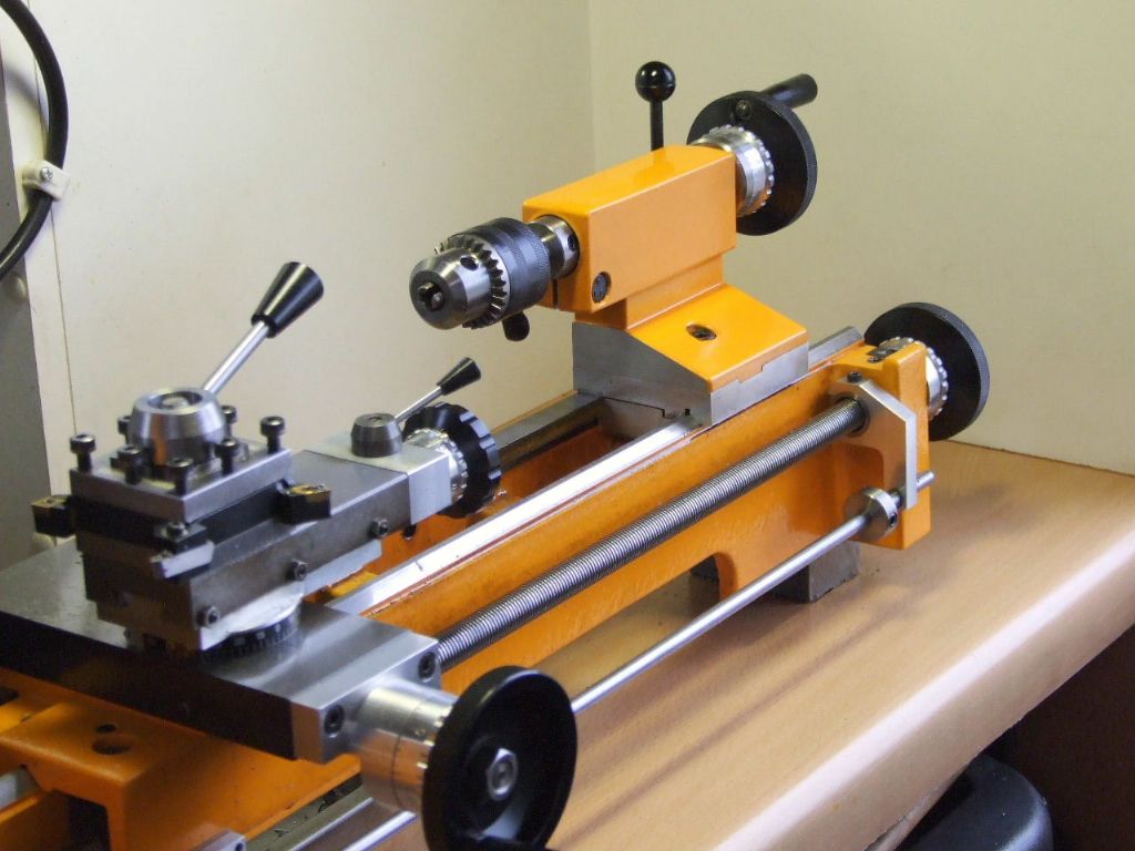
My lathe was one of the last of the Yellow models with the latest cross-slide fitting, according to the serial number. As an upgrade I fitted the ball bearing feedscrew bracket. This also removed the need to keep moving the topslide from one location to the other as it allows the cross-slide to go a further 15 mm inwards. The downside of this is the feedscrew is now not long enough as regards the outward movement. This is not a problem as a new longer feedscrew will put things right, but, it may mean drilling the feedscrew clearance hole on through the carriage. As yet I have not checked or made the new feedscrew, it is on the "to do" list.
Thus fitting the ball bearing bracket to an older lathe should give an additional 5 mm of inwards travel when combined with fitting the new carriage.
Do you need additional gib screws for the longer cross-slide travel?
It could be that you do not need to driill the feedscrew hole completely through but only deeper (the original casted carriage has an extra “dead” space between feedscrew hole/space and backwall).
I have not altered the standard Emco cross-slide in any way. Thanks for the info on the depth of the hole in the cross-slide. this will make fitting the replacement feedscrew easier if what you say is the case.
Regards
Gray,
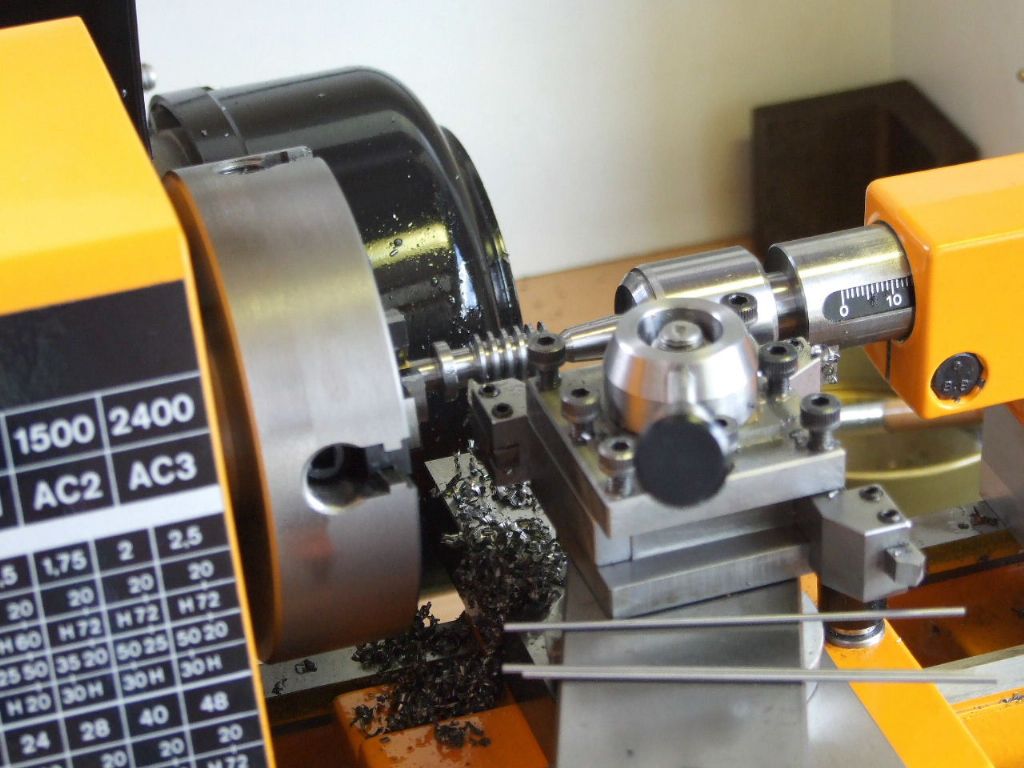
Some while back after completing the Retracting Topslide I promised those following this post some photographs on cutting the 10 TPI Worm for my 40:1 Dividing attachment.
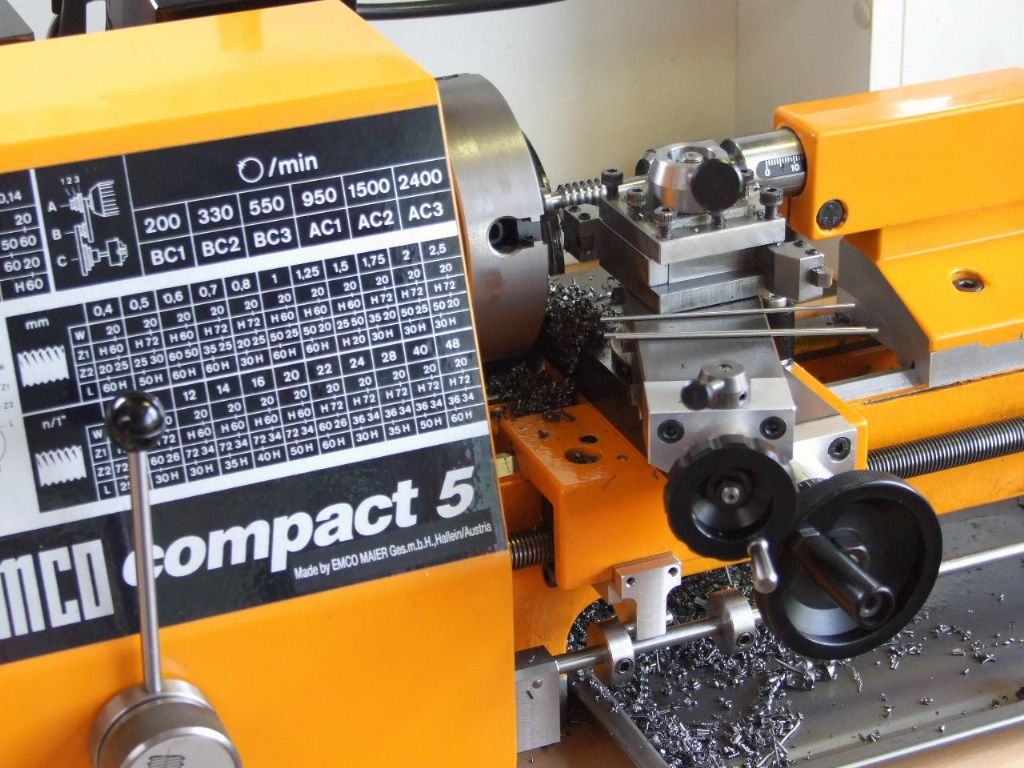
I must admit I would not want to cut such a coarse thread on the Compact 5 without the screwcutting clutch. My nerves nor reactions could stand it.
Here is a closer view of the work in progress. I was just about to check the size using the wires in the foreground. At this point there is a further 0.2 mm to be removed.
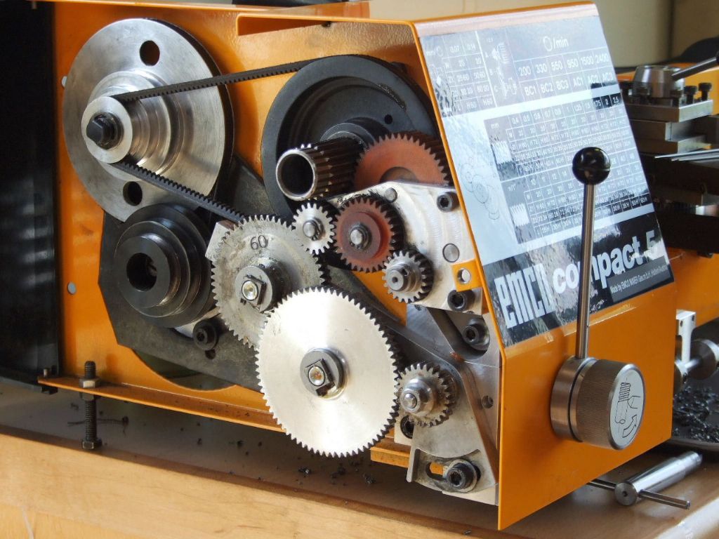
While I had laid out all the Metric gear trains in the design stage of the screwcutting clutch, there is always one that will bite back. On all the other gear trains the 72T gear is mating with the 20T output gear on the Clutch. However with 10 TPI the 72T gear is lower down in the train and as such it would, if mounted on the standard quadrant mesh with the smaller Tufnol Idler gear in the output train from the Clutch.
To get by I have made an off-set mounting block this drops down the 72T gear 16mm below the normal centreline of the quadrant. Thus another "Round to it" for the "To Do" list, is to make a new quadrant with a double row of slots to take the offending gear. This is not such a bad thing as the standard quadrant is now too long and I do consider it to be on the flimsy side.
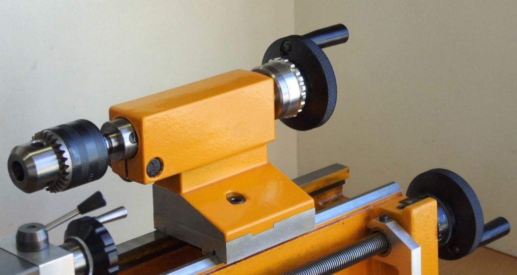
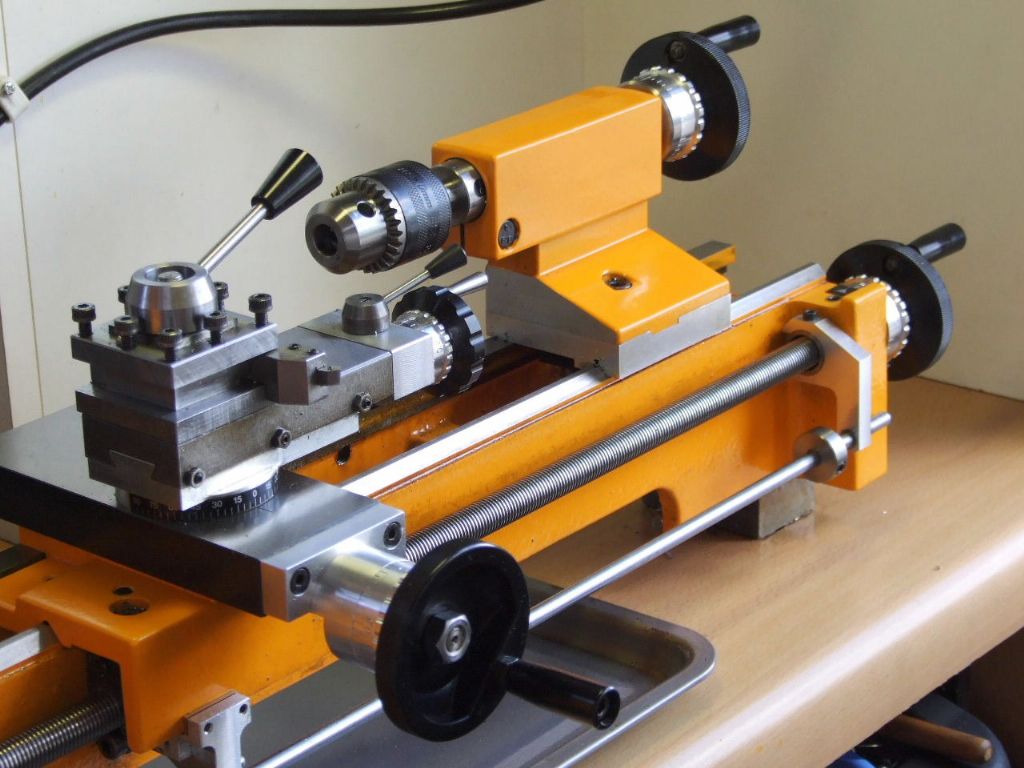
Just before the last heat wave I made a start on something I have been meaning to do for a good many years on the Compact 5. I have felt for a long time the tailstock should have an adjustable dial. Graduations are provided on the C5's little brother the Unimat and to be honest it is something I miss.
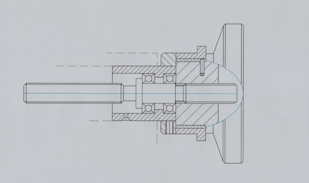
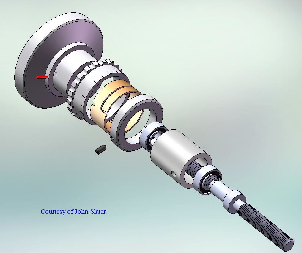
While adding the dial advantage was taken to incorporate two Radial Ball races. This mod alone is well worth the extra work. Drilling is now a doddle compared to how it was previously.
In order to accommodate the bearings a longer feedscrew was required. This also allowed the bearing housing to be made longer to take the Dial backing ring which carries the Zero line. This is adjustable to suit the operators preference.
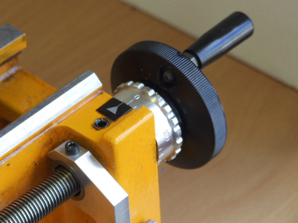
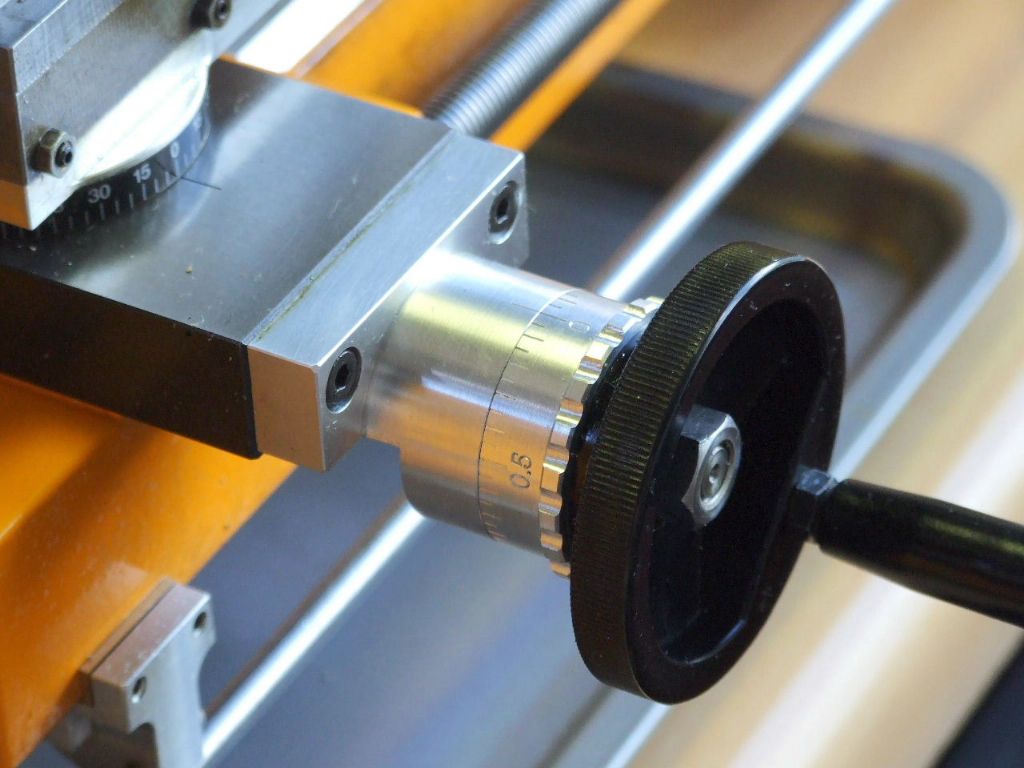
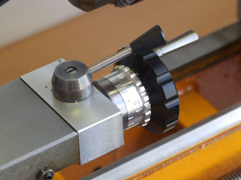
Rather than have the dial rotating on the plastic of the handwheel and all the stick-tion problems that brings. I have made a separate steel sleeve which uses my trusty friction spring from the Myford Super 7 Handwheel dial. A peg at the back of the sleeve stops this rotating. The dial I have made from aluminium and while I was at it I have made two more to replace the leadscrew and cross-slide plastic dials.
I cannot show the finished unit as I need to finish the 40:1 Dividing attachment to allow me to do the graduations on the dials. More details soon.
Following on from John's 3D image here is the Embryo Dial in-situ on the lathe. Work can now start on engraving the dial as the Dividing attachment is now finished
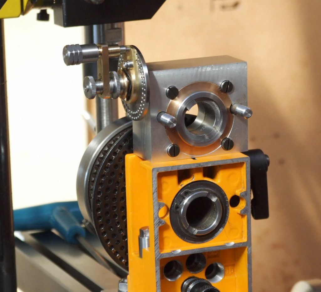
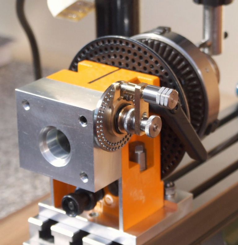
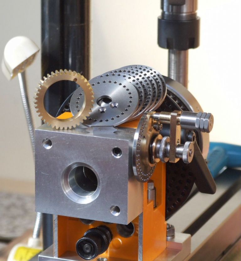
This first photograph shows the stand alone unit and how it drives the original C5 Dividing attachment. The worm gear is shown being screwcut earlier.
This is the unit bolted in position. The next view shows the additional dividing plates and a spare wormwheel, along with the homemade single point cutter. The detent has a hold out facility like most larger dividing heads, which avoids the detent being held out of engagement when doing multiple turns of the worm.
This last photograph shows work is about to start on the engraving of the Tailstock dial. Which hopefully will be followed by new dials for the cross-slide and leadscrew.
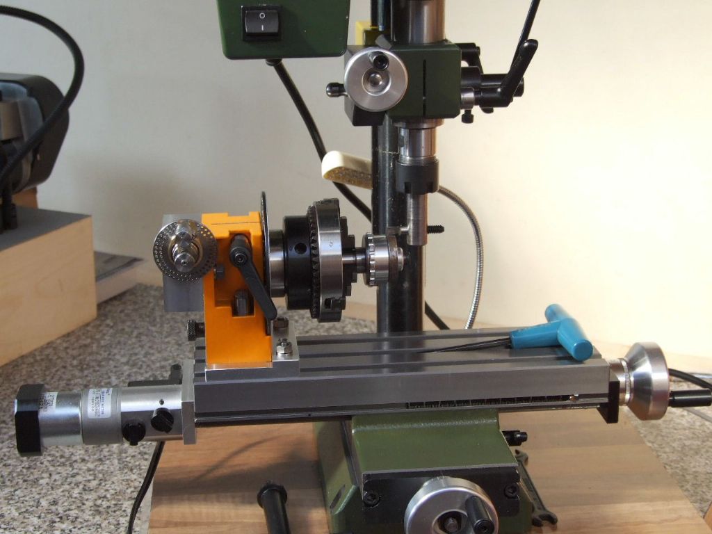
This is where the C5 and Proxxon merge, note the adaptor plate beneath the Dividing attachment. The complete attachment is on dowels to locate off the central Tee Slot. Thus it can be removed and re-fitted at will. A single dowel that the Dividing attachment abuts in the adaptor plate. Along with the step in the adaptor plate means the Dividing attachment can be removed and returned to the adaptor plate with out the need for clocking.
This view shows I have now completed all the new and replacement Dials for the Compact 5.
Here is the Tailstock dial which started the ball rolling in the first place.
This is my take on the Leadscrew Dial. I decided to stamp the numbers as per normal practice. Unlike the original dial which has the numbers parallel to the leadscrew axis. I had made provision for stamping the dials to comply with the original, but it involved a lot of extra work. If I cannot get on with this new set-up then I can always bite the bullet and make a new dial.
The cross slide dial is a much better fit as regards the gap between the dial and the endplate when compared to the standard dial. All dials are much smoother in use with none of the sticking that was present with plastic on plastic.
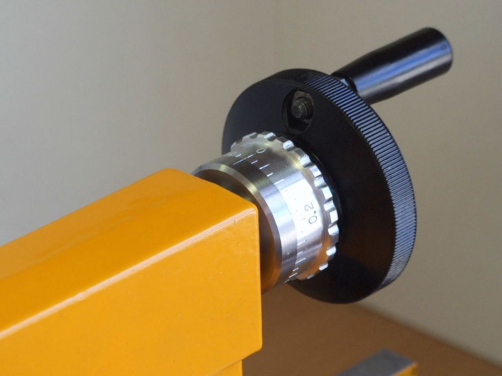
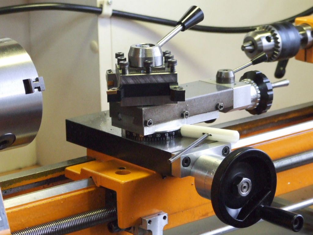
When I fitted the Retracting Topslide attachment I thought my original adjustable dial that I had made for the Unimat 3 Restoration looked a little on the small side. I therefore decided to make a new larger version which follows the rest of the machine. The new dial does allow the numbers to ascend in 0.2 of a millimetre. This could not be done on the original Unimat dial as the numbers all ran into one another.
I hope to post the restoration of the ailing C5 Tailstock soon.
When I see all your improvements coming along for the Emco C5 I am often wondering about which machines you use now to achieve this. Earlier this year you told that you removed some bigger machines from your workshop.
Therefore te question: do you all this accurate machining on the Emco C5 and your Proxxon mill, or …?
The only parts in this post which were made on my previous Emco machines are the main body for the Screwcutting Clutch, and the knurled Operating Knob for the Leadscrew engagement. Every thing else has been completed on the C5, the Proxxon mill or my restored Unimat 3.
I have been really surprised how good these little machines are. The C5 with 4 tool turret is easily as accurate as the Emco Maximat Super 11 was. Admittedly things take a little longer to make, but then the machining is the bit I like. My Unimat brings back many pleasant memories of when I was starting out in Engineering.
I have some additional turning toolholders for inserts for the C5 to make. A new base similar to the Unimat 3 for the Proxxon. As well as some linear scales for the X & Y slides and then I can get back to my model work.
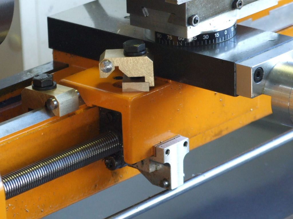
I have been a little busy with the Proxxon Mill lately and have neglected the C5 thread a little. This is the latest thing I have made, which is a double sided Bed Stop. Meaning it can be used either side of the lathe Carriage.
Because the Unimat 3 and U4 share the same Bed profile as the C5 this attachment will fit any of these machines, so while I was at it I made two. One for the Unimat 3 restoration lathe. Two are also handy when using the lathe for milling work. Such as milling a slot in a workpiece.
I used to make these for Neil Hemingway to sell years ago. At the time for purely cost reasons, I used to make them in Aluminium, but retained the Brass clamp pad. As I had two off-cuts of brass in the scrap box these were used instead.
Later over the weekend, I hope to start the reclamation of the Compact 5 Tailstock which I promised earlier in this thread.
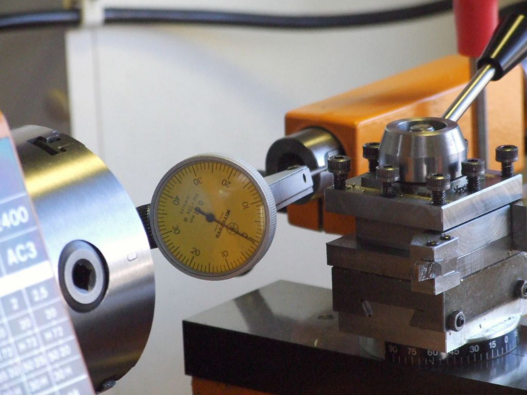
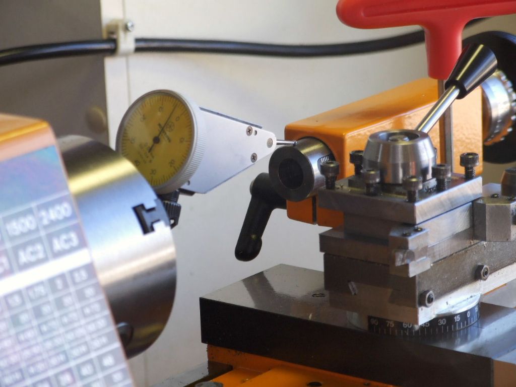
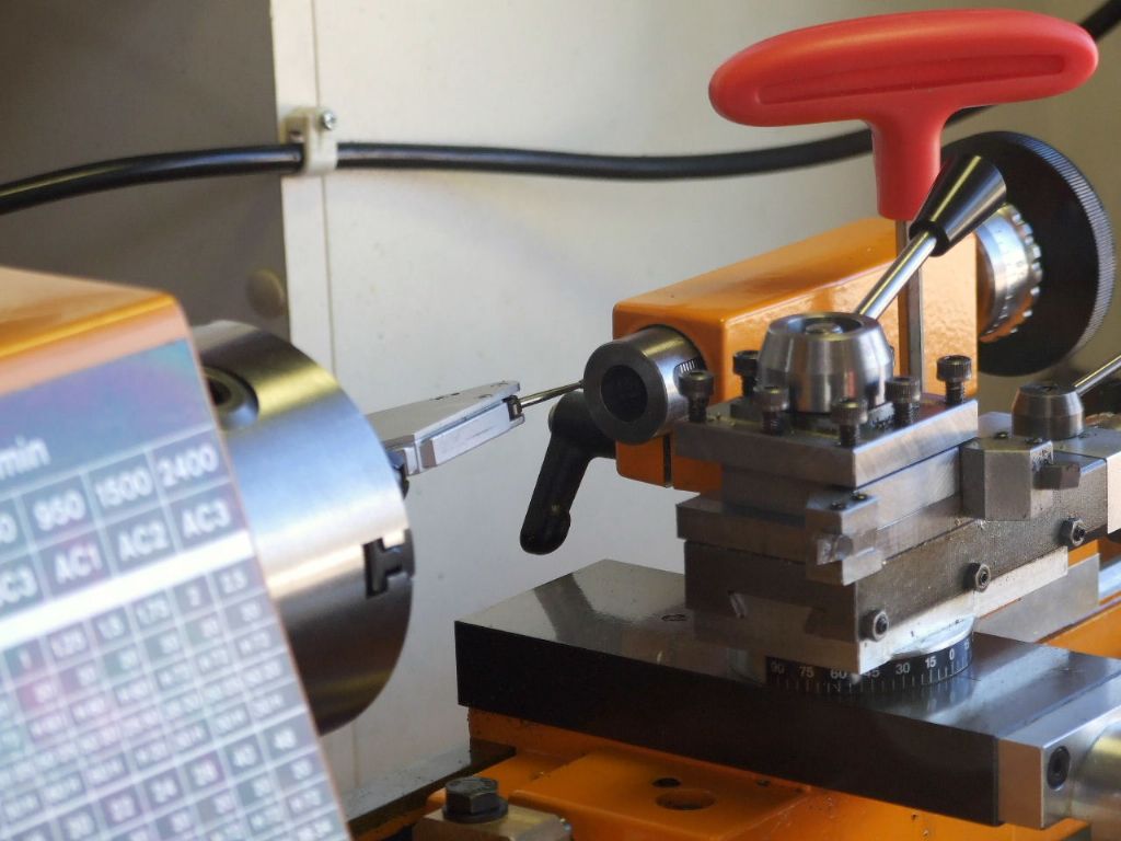
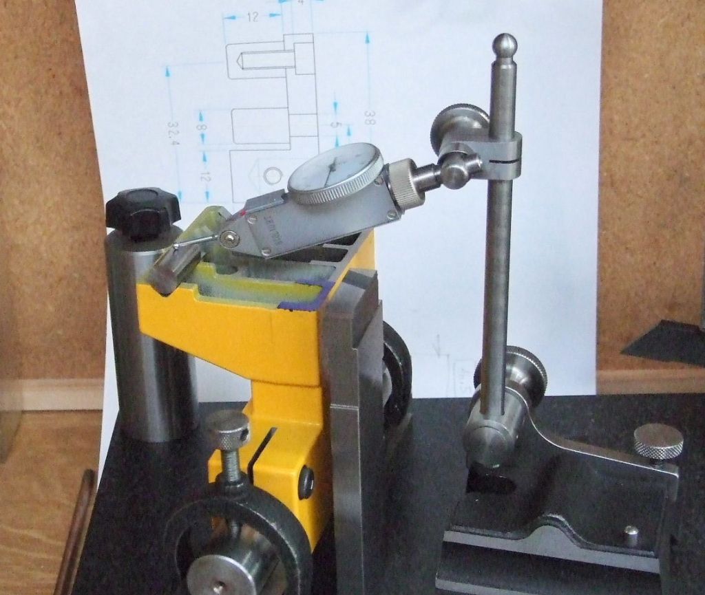
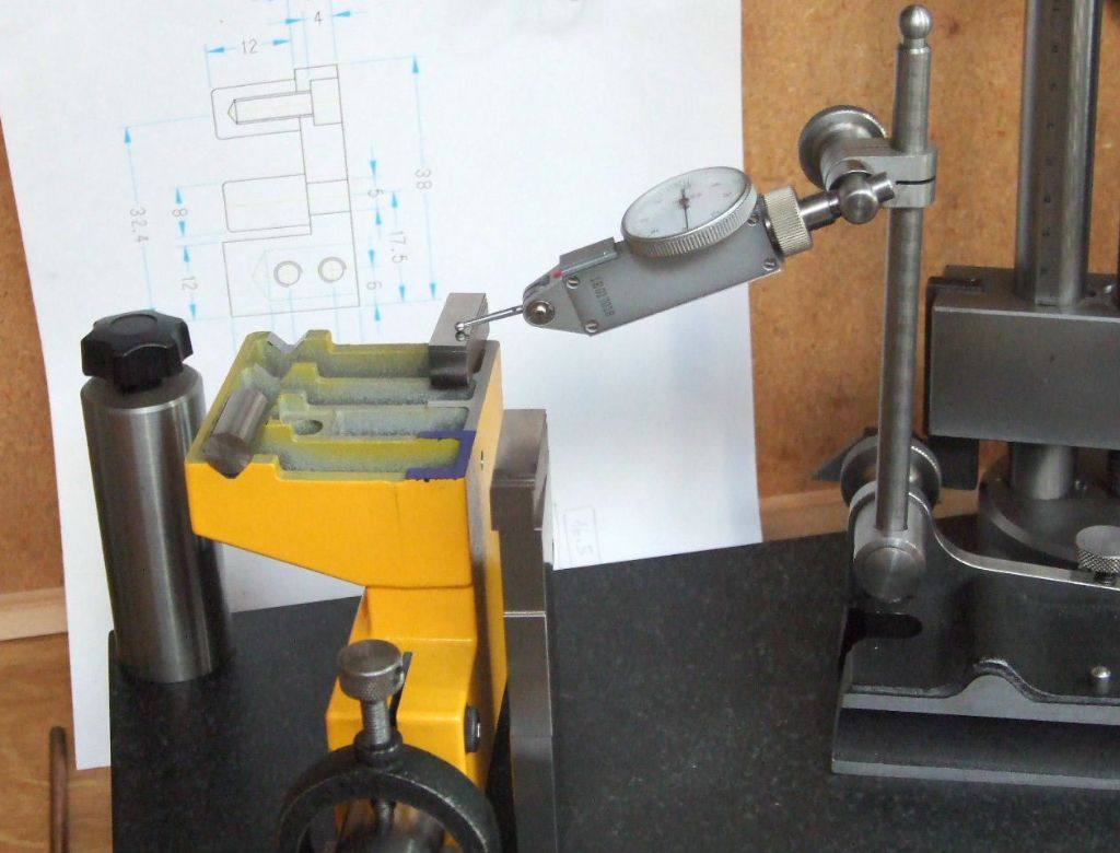
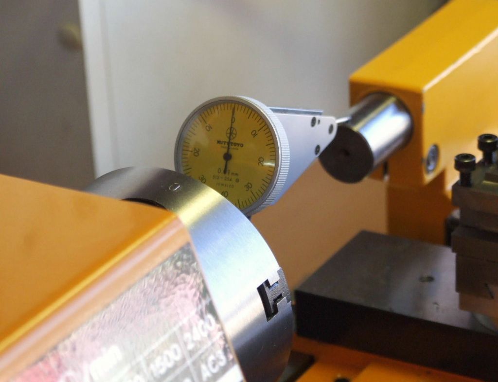
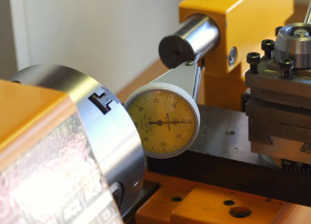
These first three photographs show how the Original tailstock was assessed. The actual tailstock shown here is the one I modified by adding the aluminium base seen in previous photographs.
The clock was set on the vertical centreline of the lathe and clock Zeroed to the height of my lathes centreline, plus half the diameter of the tailstock barrel. Using slip gauges.
It has been swung through 90 degrees to check alignment in the horizontal axis. As I would expect the clock reads Zero. As the lathe turns dead parallel when turning between centres.
In the vertical the reading is +0.03 mm, which is what I aimed for when I made the aluminium base. As the tailstock base wears-in during use it will only get better.
This is the third position which should, and does mimic the first reading, (although you cannot see).
Going back to the Original tailstock body. The first reading in photo 1 was +0.1 mm, photo 2 was + 0.05 mm and photo 3 was -0.1 mm.
In other words the tailstock body was leaning towards the operator. Another thing that was happening was I could not get a consistent result. the above are the mean values. The tailstock appeared to be rocking diagonally corner to corner.
This could be down to the flat at the rear of the tailstock not being in-line with the Vee location at the front, or visa versa.
How to check which face is at fault follows later,
The next thing to tackle was the manufacture of a 22 mm diameter parallel mandrel. This was just a piece of BMS turned between centres. I chose to manufacture a mandrel rather than use a piece of say Silver Steel, because there would be no guarantee the Silver Steel would fit the tailstock bore.
While we in the UK work to the Hole Based system of Limits and Fits. On the Continent where this lathe was made they work to the Shaft Based system. While I know a piece of Silver Steel will go in a standard UK, H7 hole. What tolerance has been applied to the Austrian hole is anyone's guess.
Without the spare tailstock which I had adapted this operation could have been a problem with the Original tailstock. I would have got around it by using strategically placed pieces of paper, but it would have been very trying.
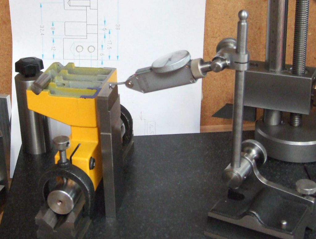
The Mandrel was made long enough to support the tailstock and rest in my matched pair of Vee blocks.
This shows the set-up, note the clamping screw in the tailstock next to the slip stack.
The slips amount to the height of the centre-line of the Mandrel off surface plate. Plus the centre height of the lathe and an additional 10.48 mm. This last dimension was assessed from the Headstock of the Unimat 3 that I refurbished as well as the new Carriage purchased from Austria.
The dimension is the height of a 10 mm diameter roller resting in the Vee in relationship to the flat on on the headstock or tailstock body.
The clock is then used to get the roller to the same height as the slip gauges. Once this is done the Vee block clamps are locked. The roller was then moved to the other end of the Vee way and checked with the clock at the same setting. It was as I suspected parallel to the table, which meant the flat was going to be at fault.
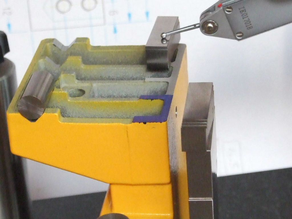
Using the 10.48 mm stack of slip gauges the clock was run over the flat. Whilst at the back in this shot it is where I would want it to be at Zero.
The area of Blue Marker pen shows that this area is higher by 0.03 to 0.04 mm. This confirms the displacement of the tailstock body towards the Operator, and the rocking from corner to corner.
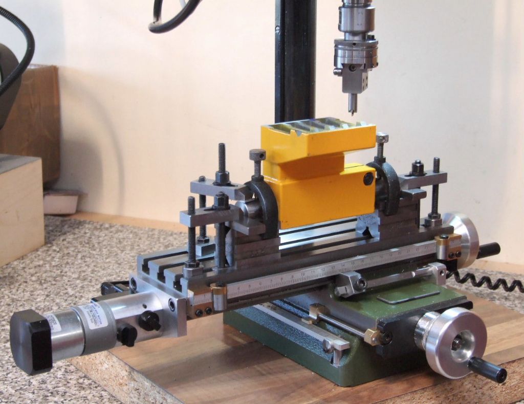
As promised here is the Tailstock set-up on the Proxxon Mill. Those who have followed the Proxxon Mill post will see why it was important to get the machine cutting perfectly square to the table.
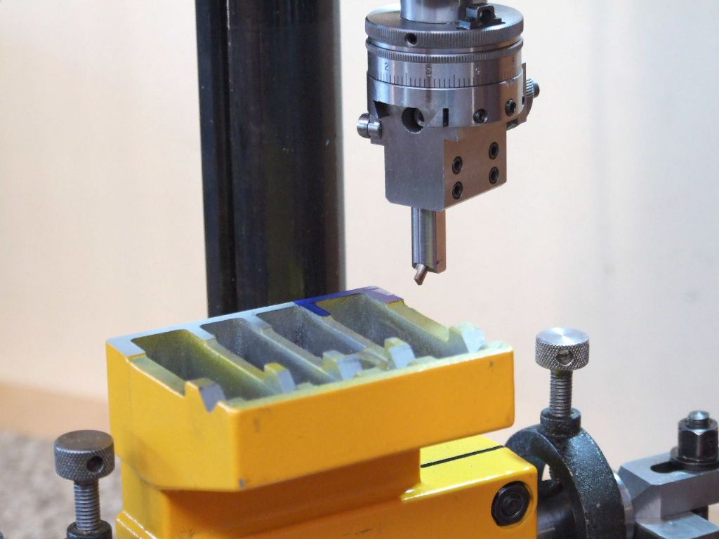
The following are the cuts taken as they happened, below is the "Touch on".
Each Cut is 0.01 mm. One of the reasons for using the boring head was so that I could advance the cutter using a DTI on the end of the boring bar. The other was I have not finished my Fly Cutter yet.
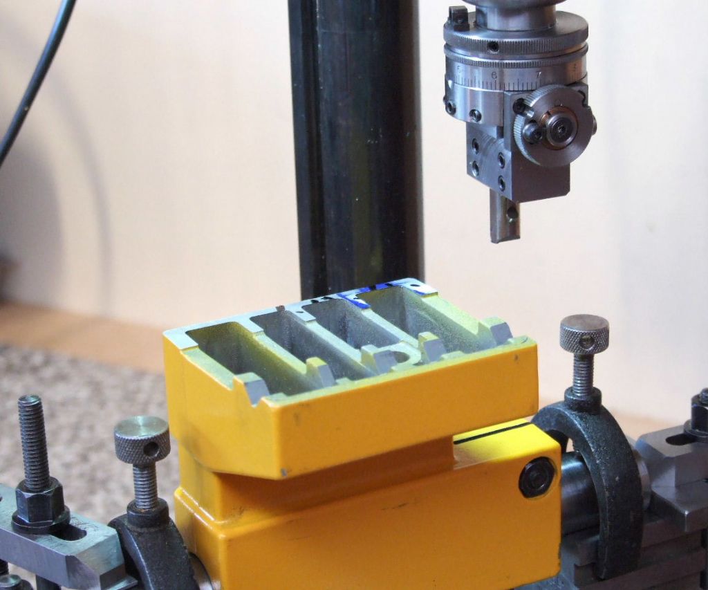
The black Dots are where metal has been removed, which is between the black Lines. It appears the Ribs are higher. This implies to me that the cutter used was probably past it's best. Pushing away from the work as each Rib was machined due to the extra pressure brought about by a dull cutting edge. Of course it may have been the work move away. This material can be quite abrasive.
The 2nd cut has extended the clean-up to the 3rd Rib.
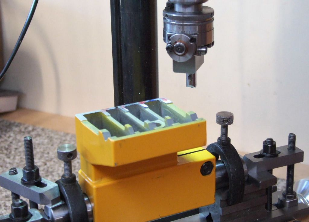
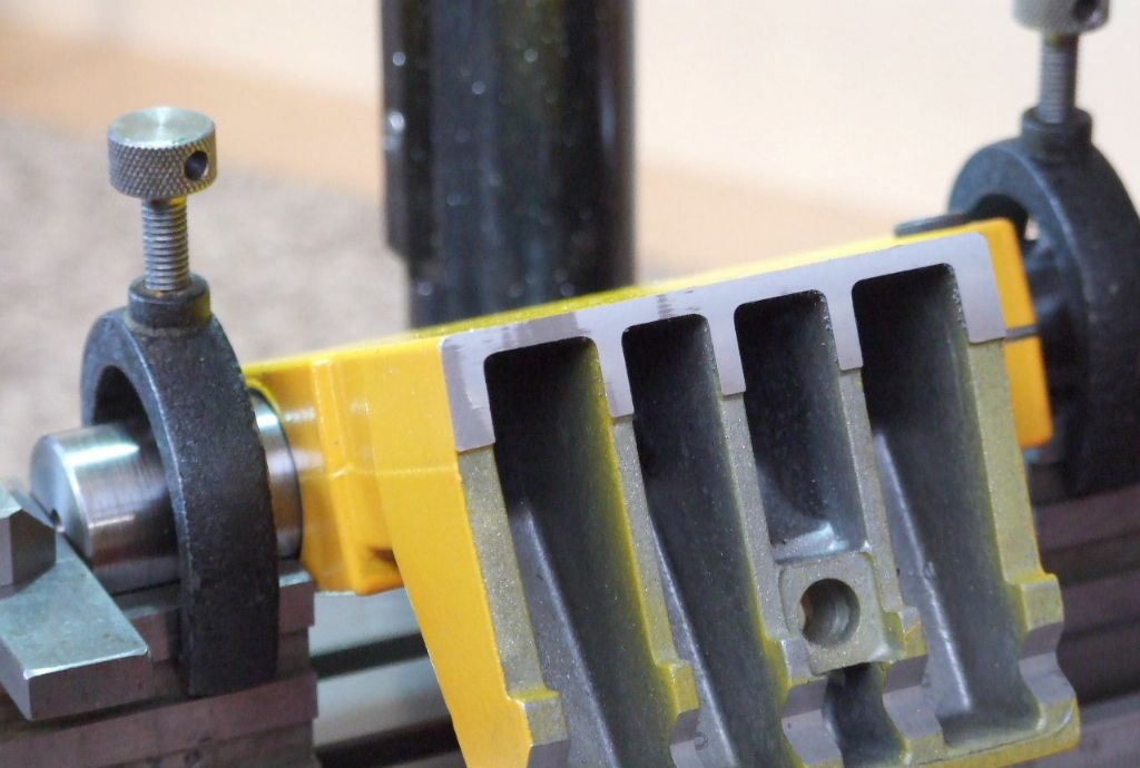
The last cut shows the clean-up has extended to the last bearing surface. This is after removing 0.03 mm, which was the initial error.
The Proof of the Pudding as it were. Back on the lathe and the vertical reading is Zero. (Centre Height plus half the Tailstock Barrel).
At 90 degrees and Plus 0.01 mm it is time to leave this job alone. Initial wear will soon have this spot on.
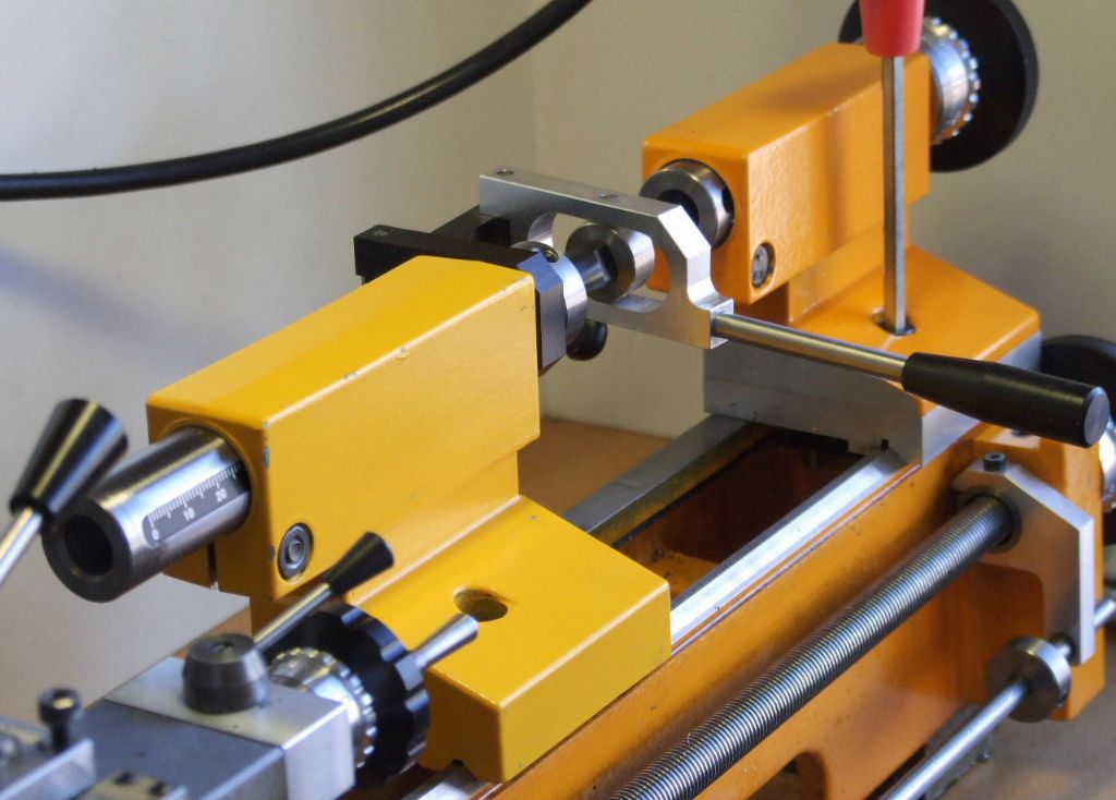
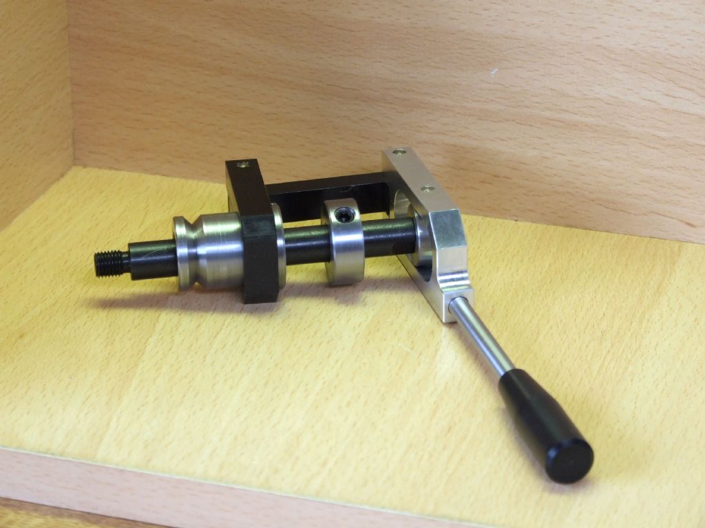
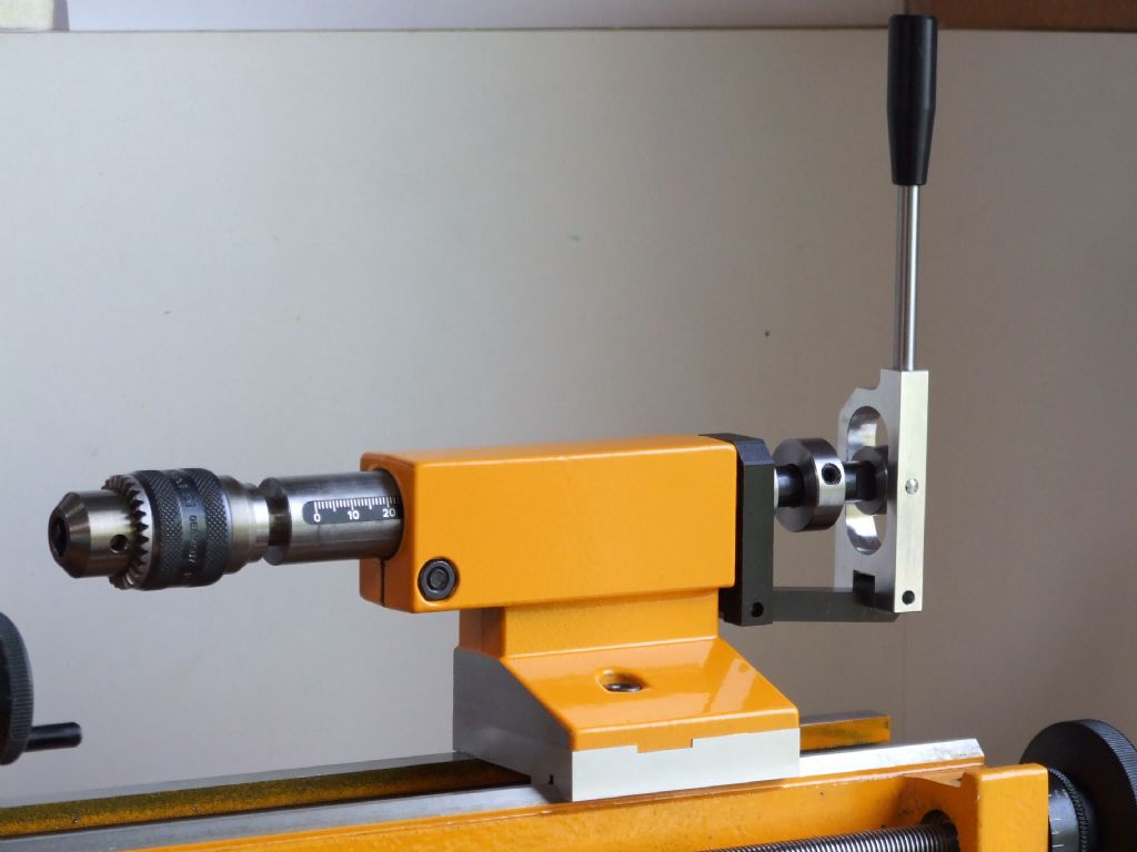
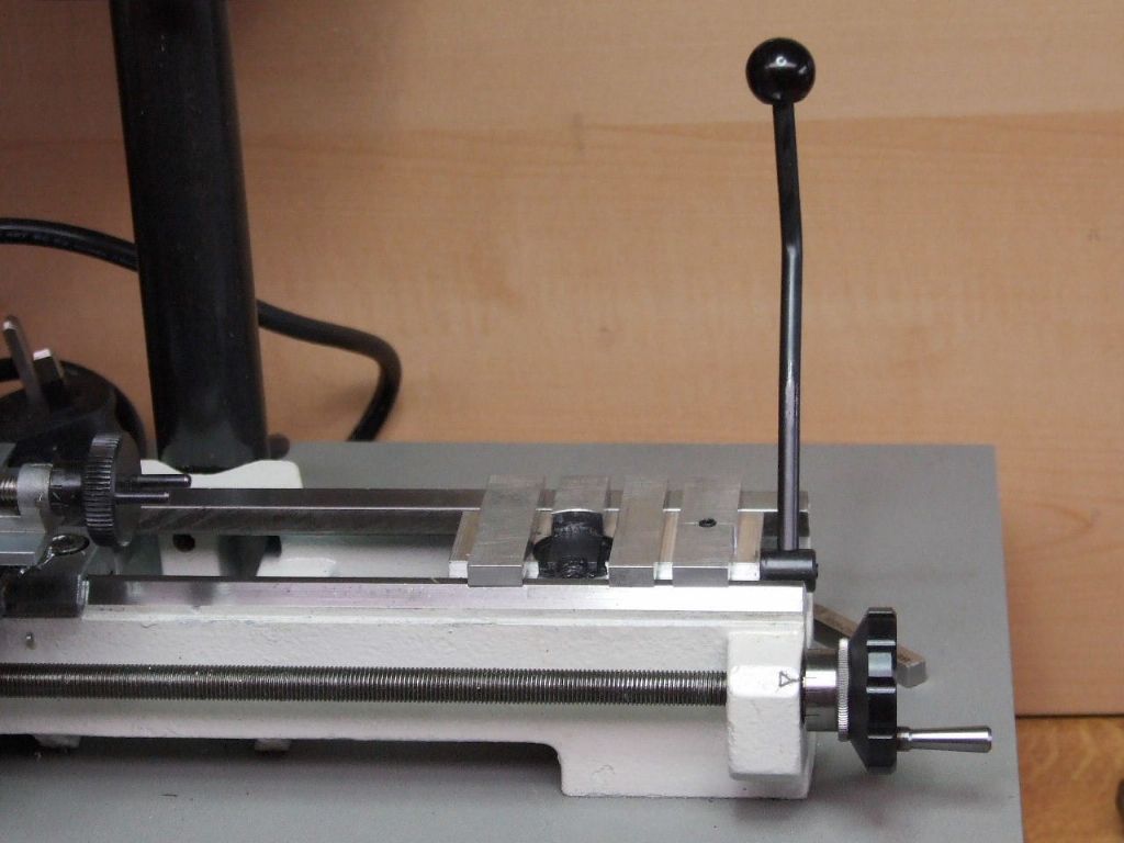
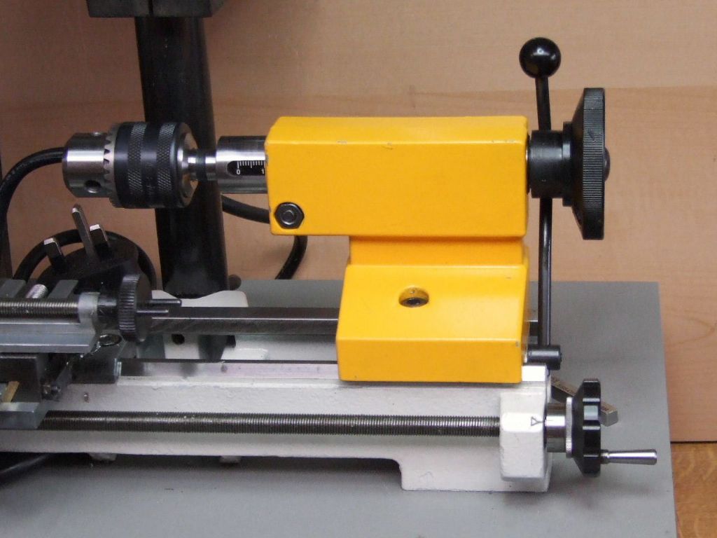
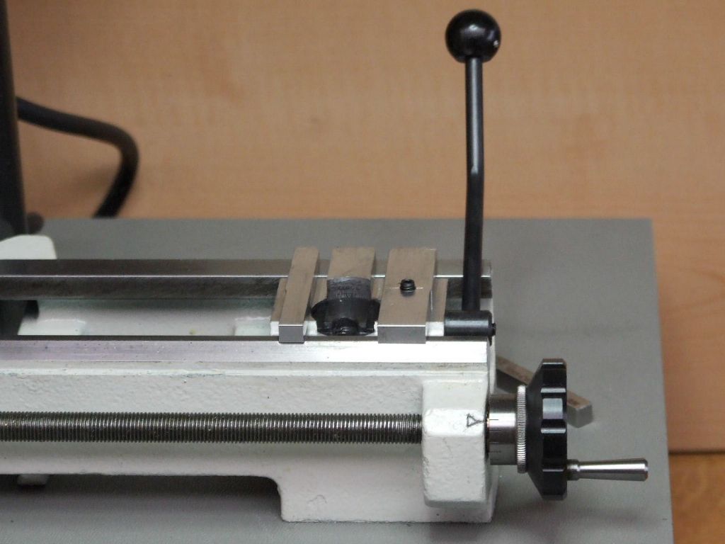
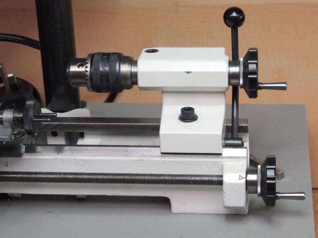
This is how this Tailstock will see out it's time with me. I have fitted my Lever attachment to this tailstock body. I have also included this because talking to a couple of people recently has shown this item that I had designed is not well known.
I do hope these notes have been of help to others, even if they do not own a Compact 5, U3, U4 or similar.
Without wanting to derail your thread, I'm very interested in knowing more about your Tailstock "Lever Attachment", as I'm keen to make one for my own Proxxon Lathe.
I recently read an old MEW (issue 10) that provided a detailed "Lever Conversion" for a Compact 5, although that one was done as a vertical attachment.
As you've chose to do yours as a horizontal version, I'm curious to know if that's because it's a better choice in usage..?
Or was this mounting chosen more as being "prototypical", based on how larger Lathes would have theirs attached?
My Proxxon PD 250/E appears to be very similar to the Compact 5, at least in its basic form & also their Tailstock construction & materials.
As both the old MEW article & yourself suggest, I've already purchased a separate Tailstock body & related parts from Proxxon, in preparation of doing the conversion.
Any insight that you might be able to provide, would be gratefully appreciated.
The original design was for the Unimat 3 which was originally designed as a horizontal attachment. This was supplied originally with a new extended tailstock barrel or spindle.
Many years ago I was asked to supply one such lever attachment for a Compact 5. This was supplied by Neil Hemingway. This used the existing C5 tailstock barrel as this had a No 1 Morse Taper. This was a simple add on unit. The Unimat 3 attachment was later modified to this design.
You will see in this design a Vee Groove in the part which fits into the tailstock body. This is how the original Emco Handwheel and Feed-screw are mounted. This then allows the lever to be placed in any position convenient and locked. I prefer the horizontal mode.
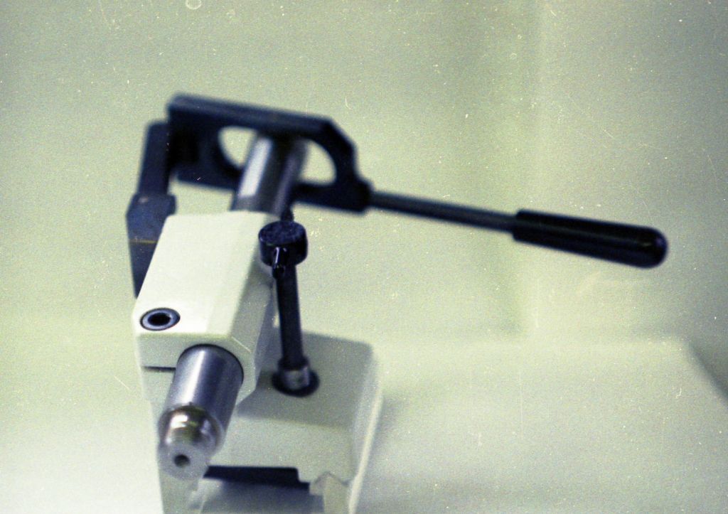
This last picture is an old one which was used for in a couple of articles on making this unit.
The design of the lever and its geometry was based on the Collet Closing lever used on a Harding HLV Toolroom Lathe.
Thank you greatly for responding with these photos & their accompanying text.
Seeing your mounting arrangement onto the original Vee Groove is very helpful, as the Proxxon uses an almost identical arrangement for mounting their Handwheel & Feedscrew.
As you've previously made these as a commercial product, may I ask what material choices you settled on for making your own personal one?
I'm assuming the rear most "silver" section which the Handle attaches to, is a block of aluminium?
I gather that central collar with the large grub screw is of steel & is acting as an adjustable stop?
Are the various "black" components also steel which has been given a Black Oxide coating?
And for each of those "pinned" hinge points, are they hardened Pins or are those joints bushed with a bronze material?
Sorry for all the questions but not being an Engineer nor Machinist, I'm trying my best to pre-empt what my possible needs will be.
There was a time many years ago when I was not a Toolmaker, and I had to ask. There is nothing wrong in that and there is no need to apologize as I am only too happy to help.
All the black rectangular parts are Anodized aluminium. The only spare part I did not have from years ago is the one plain aluminium one. The other turned parts are Leaded BMS which were commercially blacked, but again I only had the central spindle. This is threaded M8 x 1 LH Pitch to match the tailstock barrel, or sleeve, and has a couple of flats on to take an 8 mm A/F Spanner.
You are right the collar is for repeated drilling to a set depth. The use of the Bed Stop shown above is great for returning the tailstock to the same place when doing repetition parts.
All the pivot pins are 4 mm diameter groove pins to DIN EN ISO 8745. Not to be confused with Roll or Seloc Pins which are useless for this task. They come in various lengths and at the moment I cannot remember what those lengths were. These are not hard, but tough like capscrew material. As they are working in anodized aluminium which is as hard, or maybe harder than harden steel the two will give years of service without any problems. Provided they get the odd drop of machine oil something like ISO 32.
Don't think you need to anodize the aluminium. You will get an extremely long life out of plain aluminium working on this type of pin, or even silver steel. Bushings of any description would be an overkill in my book.
I find the lever tailstock handy when tapping, or using a button die. A bespoke holder for which I am currently working on among other things.
Thank you once again, your detailed information is an immense help to me on this project.
Knowing now that you've used aluminium for those rectangular pieces, it simplifies things greatly as I'll be milling them on my Proxxon FF 230 Mill.
I believe Proxxon has used the same M8 x 1 LH thread on their Barrel too, which helps as I can now dimensionally gauge & scale various items between the Proxxon & Emco.
The one major difference between our Tailstocks is that Proxxon chose to use a MT1 "short" version, which is akin to a B12 taper for Drill Chucks.
Being that I'm in Australia & having those DIN numbers for the Pins, it shouldn't be too hard to find something equivalent here or as you suggest, simply make some from silver steel.
I greatly appreciate all of your input to my questions within this thread but please let me know if you'd rather them as a PM instead.
regards Colin
Hi Colin,
I use the Proxxon drill chuck on my C5, as it is 0-10 mm capacity where as the Emco is 0-8 mm. I purchased a B12 to No 1 Morse taper arbor to mount this on from one of the ME suppliers.
I suspect things are starting to warm up with you while we here in the UK are getting decidedly cooler.
As regards the PM, I concur with Michael, a lot of people, including myself, benefit from other peoples questions. When I recently needed to get a new 2D drawing package. It was Michael's response to another members question on another post along the same lines that made me go with Qcad, so thanks Michael for your input. I am completely satisfied with my / our choice.
No prob's, more than happy to keep this whole discussion open.
So Graham, with the various aluminium components, is there a specific grade you'd recommend using for this application?
It's most likely I'd be buying short drops coming off flat bar, which typically is 6060-T5 & based on using the 4mm Pins, I'm guessing these flat pieces would need to be about 8mm finished thickness?
Already had to buy a 300mm length of EN1A-PB out of the UK for the Barrel extension, as currently buying short drops over here of any suitable steel is almost impossible.
(However if I wanted full lengths then I can pretty much buy anything)
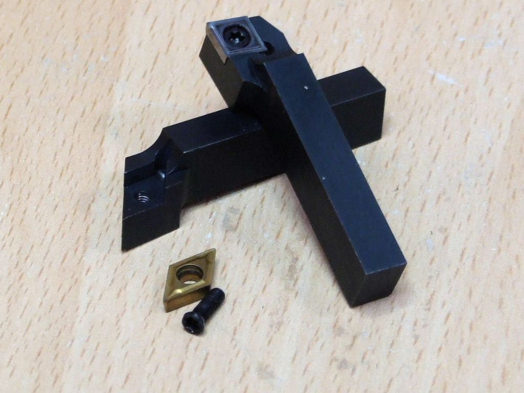
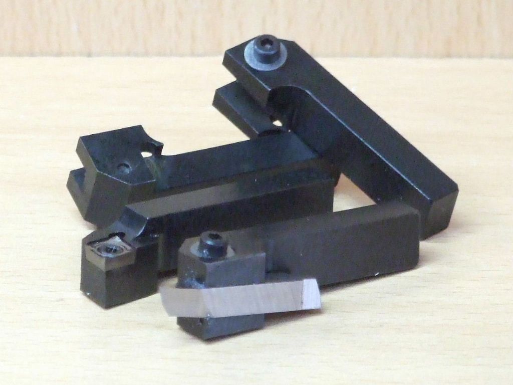
For sometime I have been wanting to make some Insert toolholders for the C5. Now I have the Proxxon mill where I want it, I decided the time had come to make some.
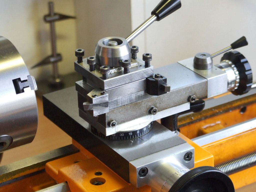
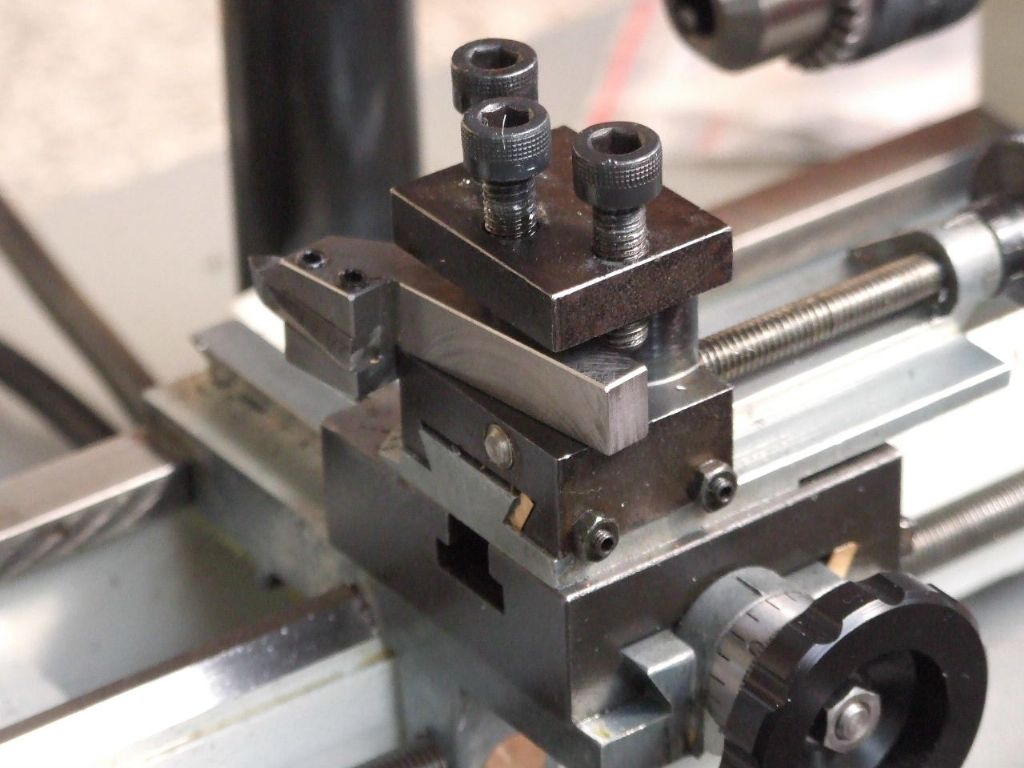
Each Insert holder has been machine such that it is automatically on Centre Height. The main body of the toolholder completely fills the tool turret so no swarf can enter and become a problem when changing tools. A step in the underside of the tool registers on the edge of the tool turret. This means the tool can be removed and replaced with no loss of index position.
I am currently working/designing a Lever Operated Tailstock Clamping attachment. This attachment will not require any machining to be done to the existing tailstock body. Because of the similarities of the C5 with U3 & 4 this attachment will also fit the Unimat's. Of course it will need to be shortened in length but that will be all.
The Tailstock conversion has moved down the list slightly. I have been making some new HSS tool bit holders. These have less protrusion than my original versions.
The tool bit is locked by one "Angledicular" M2.5 Cap screw and a 15 degree chamfered washer. I was a bit dubious about this being man enough to hold the tool bit. In use my doubts have been shown to be un-founded. I also benefit from only having to use one locking screw.
The old holders now get used on the Unimat 3.
Although this may be only a temporary measure as I have an idea for a better set-up on here.
Some while back I promised a Lever operated Clamping attachment for the C5.
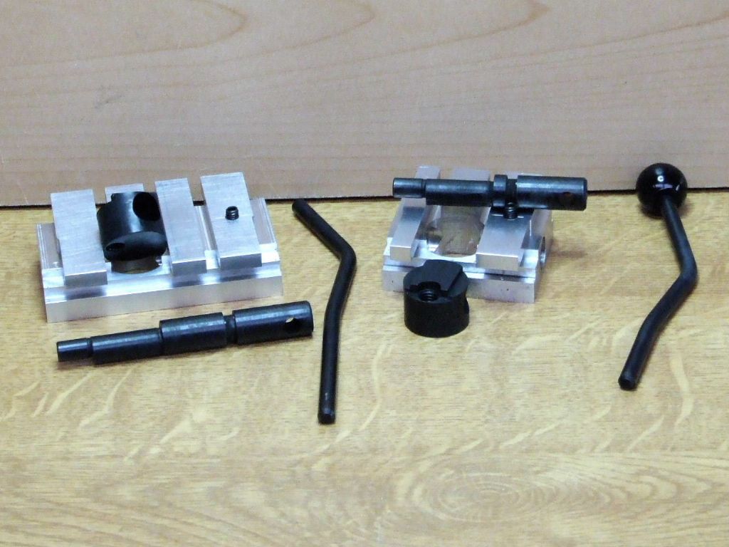
This shot shows the attachment fitted to my Tailstock salvage scheme. This still uses the same lever, eccentric and eccentric pad. The standard attachments do not require for the standard tailstocks to be modified in any way.
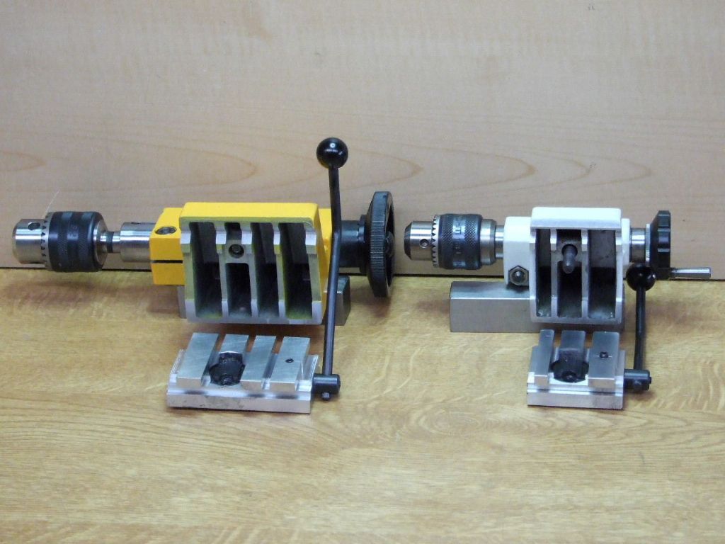
As I said earlier, what fits the C5 will also fit the Unimat. Above are the component parts to complete the conversion on both machines.
This shows the sculpting required to miss the internal strengthening ribs.
This shows the C5 parts assembled and fitted to the Unimat 3 for convenience as regards photography. Below with the tailstock body fitted. No more searching for that Allen key, or having the key foul the topslide if the key is left in-situ.
Lastly we have the Unimat base fitted to the lathe.
Because the C5 tailstock body casting fouls the Leadscrew handwheel on both the Unimat and the C5 it will not slide on and off the Bed. The Unimat tailstock casting does and the whole unit can be removed at will once adjusted. Here is the attachment waiting for the tailstock body.
Here is the Unimat tailstock completed. As these attachments sit on the bedway in their own right. When the tailstock body is fitted the whole unit slides up and down the bed with a nice silky feel. The attachment also ensures less debris can enter beneath the tailstock to bed interface as the design clearance is only 0.05 mm (0.002" )
This concludes the Modifications to the Compact 5.
The only other item I am considering making is a Motorised Toolpost spindle, but as this is a separate stand alone attachment, it will be probably be described in a separate post.