Emco Compact 5 Modifications

Advert

Emco Compact 5 Modifications

Home Forums Manual machine tools Emco Compact 5 Modifications

Viewing 25 posts - 1 through 25 (of 82 total)
  • Author
    Posts
  • #14565
    Graham Meek
    Participant
      @grahammeek88282
      Advert
      #598301
      Graham Meek
      Participant
        @grahammeek88282

        After deciding to downsize my workshop in January, the need to get the Compact 5 (C5) up to a standard I was comfortable with became a priority. The use of my larger machines would be of benefit while they were still here.

        Having had the luxury of the Screwcutting Clutch on the Maximat Super 11 it was something I was not happy to do without. The C5 had always been tempting me to do this mod, so during my recuperation in February I set about designing the attachment.

        The above view shows the Mk1, and it also shows you really need to be in the workshop more. The reason being I had forgotten to allow for the dis-engagement of the Leadscrew. This being a necessary requirement on the C5, other wise in Manual mode the operator has to turn the banjo gears as well.

        This need to retain the C5 disengagement Knob meant the Operating lever would need to move from the chosen site where the knob was to in front of the headstock. Thankfully during the need to do a complete redesign of the main body it was possible to have both controls in the one place.

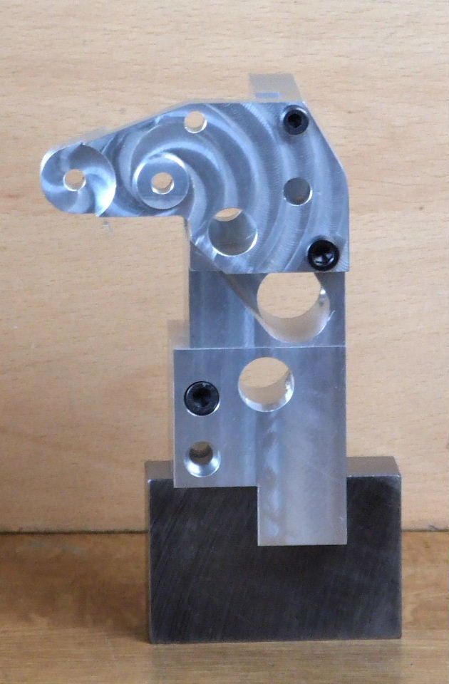
        compact 5 main body 1.jpg

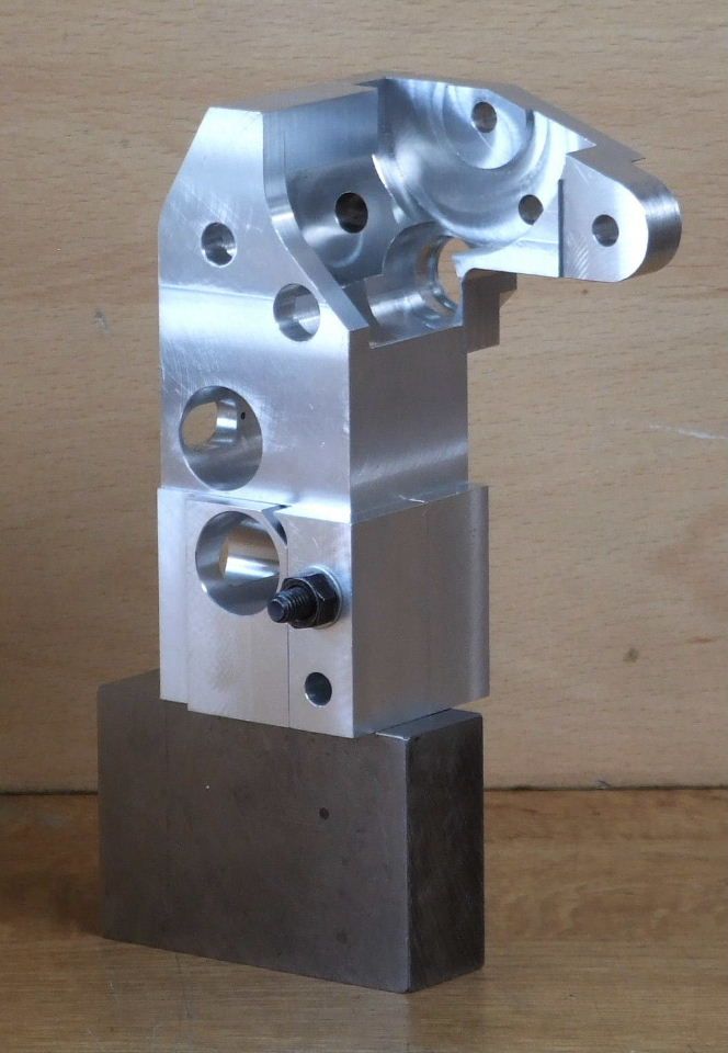
        compact 5 main body 2.jpg

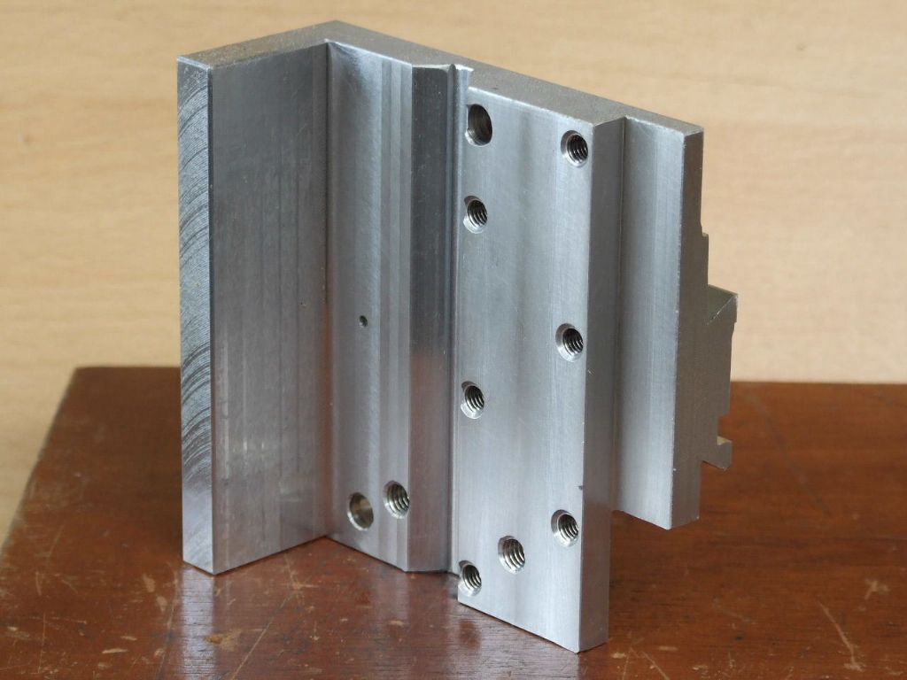
        The keen eyed amongst you will notice the main body is now in two halves, or parts. Again had I have been a more frequent visitor to my workshop at the time, I would have noticed the Bracket welded to the inside of the Headstock cover, which takes the cover locking screw.

        compact 5 screwcutting clutch.jpg

        Had it been possible to retract the leadscrew with drive key attached through the bearing in the lathe bed, then the original design would still have worked. Unfortunately the key stands proud of the shaft and this cannot happen. Thus there was nothing to do but start again with two halves, and yes this was after I had machined the main body in one. Of course I could have cut the bracket off, but that is not how Graham operates.

        The redesign also threw up another problem, in that the Dog Clutch, because of the split line needed to sit higher in the upper part of the main body. Unfortunately this brought the dog clutch selector into conflict with the drive belts when changing to the lowest Mandrel speed. This was eventually overcome by machining a flat on the selector similar to the flank on a camshaft. An eccentric balance weight is yet to be made and fitted to the outer end of the selector shaft.

        A new bearing assembly was also made for the Leadscrew handwheel which has some Radial ball bearings in. The housing was extended towards the Headstock to provide the anchor point for the outer Trip Rod support. The ball bearings will eliminate wear to the leadscrew end face and give better repeatability when screwcutting.

        While I have used this lathe for screwcutting in the past, it was a rather hair raising experience. This attachment now completely eliminates the heart stopping moment as the tool approaches the chuck jaws.

        I will in due course go on to describe other attachments for the C5, two of which get the benefit of the screwcutting clutch. I hope you have enjoyed my rather long winded post.

        Regards

        Gray,

        Edited By Graham Meek on 15/05/2022 11:20:55

        Edited By JasonB on 30/06/2022 20:35:31

        #598367
        Kiwi Bloke
        Participant
          @kiwibloke62605

          Hi Gray. Inspired and inspiring! When I saw your post announcing your intention to down-size, and to concentrate on the Compact 5, I was tempted to ask facetiously whether we would be seeing a full screw-cutting gearbox, with leadscrew single dog clutch for it. I didn't because downsizing decisions are too often the result of adverse circumstances, and I certainly didn't wish to be insensitive. However, it seems you're well on the way to elevating this machine from near-toy level to Serious Machine status, so perhaps the question is now part-answered… I'm sure we're all going to be fascinated by developments.

          It seems to me that the Compact 5 has serious design defects, predisposing it to problems resulting from wear, that warrant attention, perhaps before embarking on complicated enhancements – well, that's true of my machine, at least. Have you any interest in re-engineering the cross-slide feed 'nut', which, on earlier machines, is cut directly into the saddle, and is neither adjustable nor replaceable? Also, will we see leadscrew half-nuts and saddle handwheel feed, as (IIRC) hinted at in a previous post?

          Edited By Kiwi Bloke on 16/05/2022 06:57:43

          #598369
          Joseph Noci 1
          Participant
            @josephnoci1

            Very nice work as usual Graham. I was not aware of your trials and do wish you well.

            Difficult to lose the Super-11…I trust you will always have a place for the FB-2 though..

            From the machining marks on the Clutch upper body it seems the process was carried out under CNC control? As usual, a complex piece done well! Keen to see it come together.

            Joe

            #598392
            Graham Meek
            Participant
              @grahammeek88282

              Hi Kiwi Bloke,

              Thanks for your kind comments, there were times when I nearly abandoned the whole idea. Thankfully things are now on the up and life goes on.

              I'd like to take the opportunity to mention that I don't think a lot of people realise the cross-section of the C5 Bed ways are identical to the Unimat 3/4. I recently posted on here, about the restoration of a Unimat 3 that was given to me. It was a bit of a basket case and was fitted with a large induction motor all suspended off the headstock.

              Despite the obvious abuse to this machine in it's life, there was zero wear on the bed ways. The Tailstock and Cross-slide assembly were worn but the wear was nothing like I was expecting.

              Fortunately Emco saw the light with my C5 as this one comes with an adjustable / replaceable cross feed nut. The Leadscrew nut also benefits from a backlash adjustable feed nut. The trip-rod bracket is anchored off this adjustment screw.

              Thus I think given my intended use for these two machines I don't see wear being a problem.

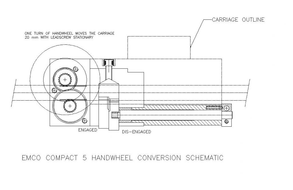
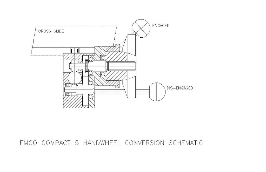
              I did draw-out such an apron attachment some while ago, but as yet I have not got around to making it.emco compact 5 handwheel conversion p1.jpg

              emco compact 5 handwheel conversion p2.jpg

              Whether I ever will, is another story, I might if I get the chance to obtain another C5.

              Regards

              Gray,

              Hi Joe,

              As mentioned above things are on the mend now, so I am doing OK thanks. The C5 project has been a God send really, if a lot of very hard work given the timescale I set myself.

              Unfortunately the FB2 is going as well. While it will be hard to see both of them go, it has to be done sometime. Better to do it while I am able to. The machines will make someone else happy and I hope they get as much enjoyment out of them as I have had. I am really looking forward to using the smaller machines, I started out with a Unimat SL 64 years ago.

              As regards the CNC, sorry appearances can often deceive. Everything was done by first principles and the trusty Emco Rotary table. Total machining time was just over two days.

              Regards

              Gray,

              #598458
              Graham Meek
              Participant
                @grahammeek88282

                One thing I did forget to mention is that the gears were made using the Emco Compact 5 Dividing attachment and are all 1 MOD.

                Regards

                Gray,

                #598485
                Jouke van der Veen
                Participant
                  @joukevanderveen72935

                  Dear Graham,

                  Your design of the Emco C5 looks for me an interesting extension for the lathe.

                  What I not yet fully understand is the working of the engagement/dis-engagement mechanism.

                  Another (remaining) question is if the handwheel could be placed to the right hand side of the saddle so that the latter can move closer to the headstock.

                  Regards,

                  Jouke

                  #598537
                  Graham Meek
                  Participant
                    @grahammeek88282

                    Dear Jouke,

                    Stops on the trip rod running along the front of the machine can be set to any desired thread length, with-in the limitations of the machine. The trip rod moves to the left or right depending on the operating lever position. Which dictates whether the the thread is a RH or LH. Moving the operating lever to the right means the trip rod moves to the left and visa versa.

                    The operating lever works the banana shaped plate, at one end of this is the trip rod and at the other is the dog clutch selector. Thus any movement of the trip rod directly affects the dog clutch selector.

                    As the carriage moves along the bed during screwcutting it makes contact with the stop, 2.5 mm later the dog clutch is disengaged. Moving the operating lever in the opposite direction, after withdrawing the tool, returns the carriage to the start position.

                    As there is only one tooth on the dog clutch it can only pick up the drive at one pitch intervals.

                    Regarding the hand wheel position, this end was chosen so as to utilise the existing leadscrew nut fixing position and to retain the original operating force position on the carriage.

                    In my experience there is always a dead space at the headstock end of the bed due to the chucks, faceplate and catch plate attached to the mandrel. I therefore did not consider there would be much loss of travel. However in this instance I may be wrong.

                    I hope these notes help,

                    Regards

                    Gray,

                    PS

                    I have just completed a new topslide feedscrew using the above attachment, I hope to post a photograph soon. Which is for the next phase of the mods, a Retracting Topslide.

                    #598554
                    Jouke van der Veen
                    Participant
                      @joukevanderveen72935

                      Dear Graham,

                      Thank you for your extensive information. I have to study this.

                      Concerning the engagement/dis-engagement mechanism there could be some misunderstanding.

                      I meant the design of the engagement of the saddle to the leadscrew in combination with the handwheel (not for the screwcutting at the left end of the leadscrew, which I have to study).

                      I have now a complete Emco C5 with an adjustsble cross feed nut and an extra bed with saddle + crossslide without adjustment. The latter is used as cross table for the Emco C5 milling column. I had some ideas to replace the non-adjustable nut but I am also (slowly) working on a motor driven cross slide. In this case a cross feed screw is fixated in the saddle and a stepper motor with a hollow shaft attached to the front of the cross slide is running on the screw. The hollow motor shaft should then contain an adjustable nut rotating on the steady cross feed screw. Alignment of the steady screw and cross slide/motor movement is a major issue. I hope this description is clear.

                      I am interested in improvement of my Emco C5 but I hesitate to make irreversible changes (in other words: damage) to original Emco parts.

                      Regards,

                      Jouke

                      #598584
                      Graham Meek
                      Participant
                        @grahammeek88282

                        Dear Jouke,

                        The leadscrew engagement on the Handwheel conversion is carried out by the lever on the left-hand side of the carriage. This lifts a cylindrical half nut via an eccentric into engagement with the leadscrew. The cylindrical half nut is keyed to stop it rotating so alignment with the leadscrew is always assured. (One half nut has been used on numerous occasions in the past by various lathe manufacturers).

                        While your C5 powered cross feed sounds an elegant design. I think if I were trying to do this I would start with a C5 CNC cross slide and carriage assembly. These regularly come up on the Internet for sale. I think this would be an easier starting point. A plus point is these parts are, I believe, made from Cast Iron.

                        With regards to my design modifications. I pride myself in that I do not modify the existing machines in any way. I always make use of existing tapped holes for attachment points. No existing Emco part was modified in this recent design and my C5 could be put back to standard in a matter of minutes.

                        Regards

                        Gray,

                        #598757
                        Graham Meek
                        Participant
                          @grahammeek88282

                          Work has ground to a halt on these projects for a short while. I need to spend time getting the larger machines out of the workshop.

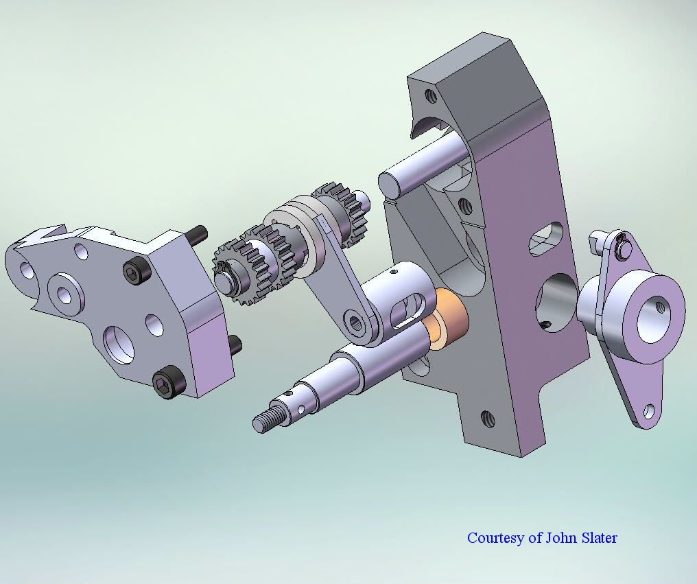
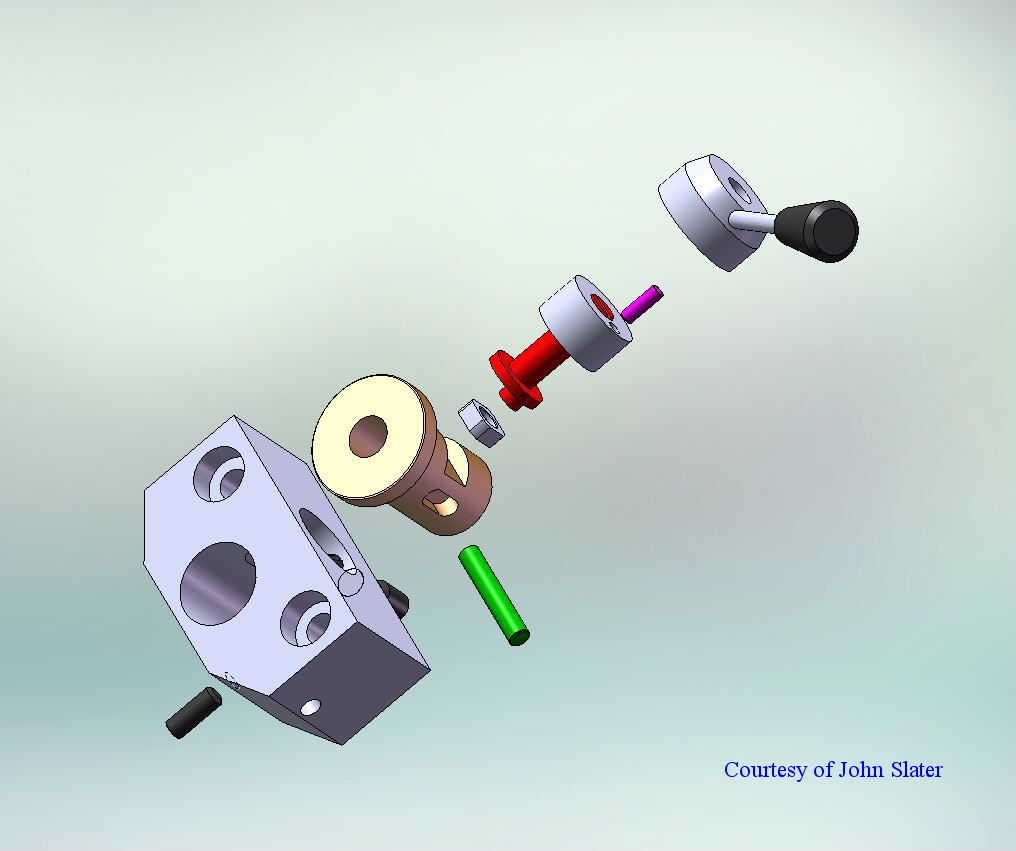
                          As a taste of what is coming I have enclosed one of John Slater's 3D views of the Retracting Topslide attachment.

                          c5 retract john slater.jpg

                          Since John has made this drawing I have moved the Operating handle to the other side of the unit. That way it does not foul the Tailstock.

                          Regards

                          Gray,

                          #599644
                          Graham Meek
                          Participant
                            @grahammeek88282

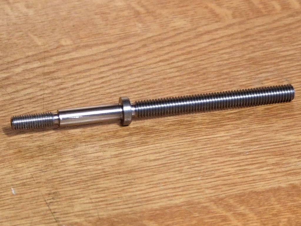
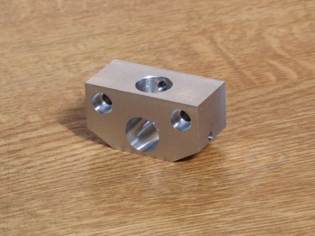
                            Despite the workshop being in mess due to the larger machines going. I have had a chance to make the new Topslide Feed screw and the Main Body for the Retracting Topslide.

                            compact 5 retracting topslide feedscrew.jpg

                            This was machined on the C5 from a long old 10 mm bolt. I find this material machines well and screw cutting is a pleasure. As was using the Screw cutting clutch on the C5. Of course it would have been quicker with the retracting topslide.

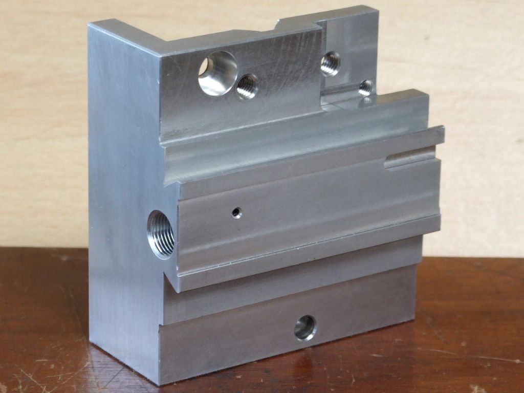
                            main body.jpg

                            The Main Body was machined on the new Proxxon Mill and after locating all the holes by co-ordinates the bores were finished on the C5 using the 4 Jaw chuck.

                            Regards

                            Gray,

                            #603635
                            Graham Meek
                            Participant
                              @grahammeek88282

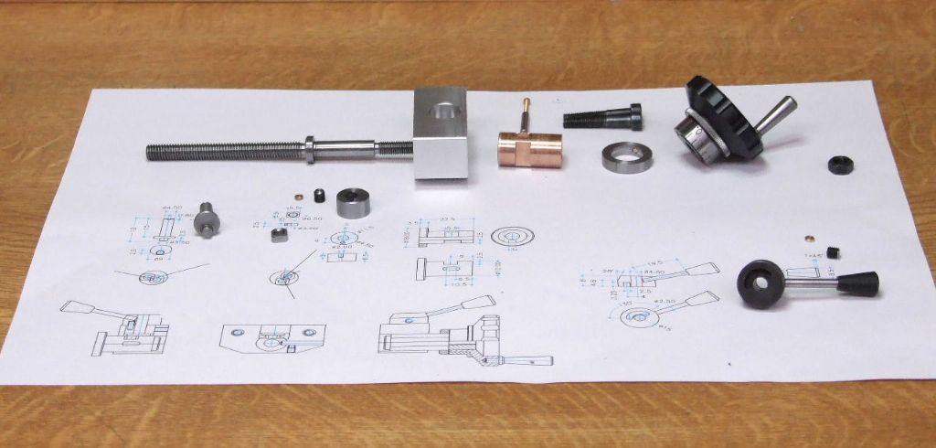
                              Now I have the workshop almost straight I have taken a breather and done some more machining.component parts of c5 rt.jpg

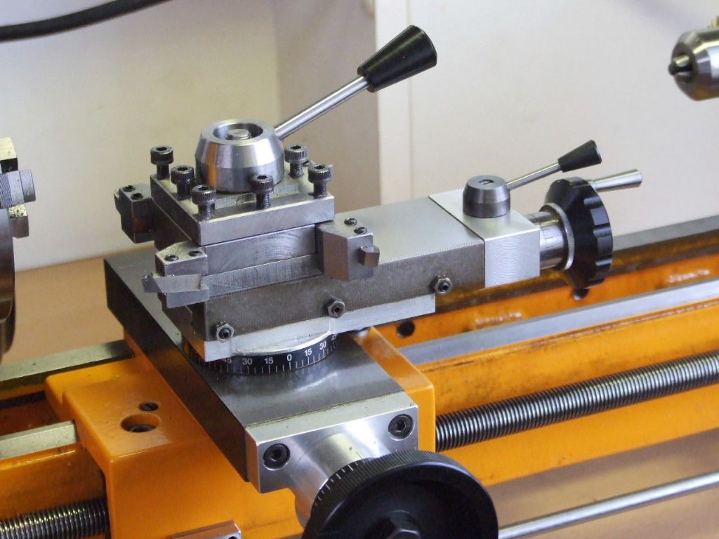
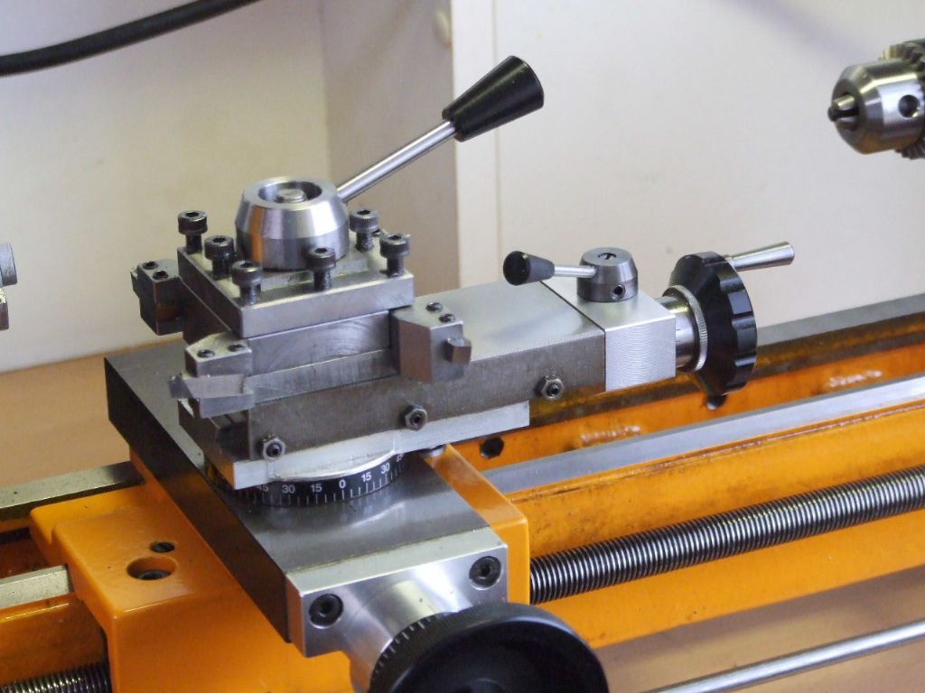
                              These are all the parts laid out ready for assembly. Below is the finished attachment fitted to the lathe.

                              fully forward.jpg

                              This is the fully forward position, note the position of the topslide end with regards to the aluminium topslide base.

                              fully retracted 4 mm.jpg

                              This view shows the slide fully retracted, the distance moved is 4 mm. Due to the longer feedscrew bearing the topslide has a much smoother action now.

                              I am hoping when I post the next photographs it will show the slide in use. It will be cutting a 10 TPI worm gear. This will be part of an attachment to bolt directly to the C5 Dividing attachment which will give this attachment a conventional 40:1 Dividing facility. This however is a way off as yet as I have the table feed for the Proxxon mill to finish first.

                              Regards

                              Gray

                              #607423
                              Graham Meek
                              Participant
                                @grahammeek88282

                                I thought those Compact 5 owners with cross slide feedscrew backlash problems might like to see what was in my post from Emco Holz & Hobby this morning.

                                compact 5 carriage.jpg

                                This is a brand new part and machined from the solid. It utilises the newer inserted feedscrew nut with backlash elimination. I think most of the feedscrew parts are available separately.

                                compact 5 carriage underside.jpg

                                The underside view shows the bearing surfaces to be continuous not as in the original die cast version, which had pockets moulded into the bearing surface. Because there is now probably more bearing surface the width of the Carriage has been reduced by 15 mm. From what I can tell most of this is taken off the front edge of the carriage.

                                Regards

                                Gray,

                                #607447
                                Jouke van der Veen
                                Participant
                                  @joukevanderveen72935

                                  Hallo Gray,

                                  I know this solution for the thread wear-out in the original carriage without adjustable feedscrew nut.

                                  Emco introduced a cast solution for it in 1985. For that solution you needed also a longer cross-slide and a longer spindle compared with the originals from before 1985. See the Emco Compact 5 manual.

                                  My question is now: can you use the original shorter cross-slide and spindle for this solid carriage (because width is reduced by 15mm)?

                                  Regards,

                                  Jouke

                                  #607517
                                  Graham Meek
                                  Participant
                                    @grahammeek88282

                                    Hello Jouke,

                                    My wording of the actual reduction in width, may have mis-led you somewhat. The dimension from left to right of the carriage, the bit that sits parallel to the lathe centreline has been changed from 115 to 90 mm.

                                    I was aware of the changes made during the Emco upgrade, and I think my ball bearing version for the cross-slide Handwheel Bracket will restore the correct travel on the earlier lathes. As well as giving an improvement to the cross-slide handwheel bearing.

                                    Regards

                                    Gray,

                                    #607533
                                    Jouke van der Veen
                                    Participant
                                      @joukevanderveen72935

                                      Hello Gray,

                                      Thank you.

                                      There was already some doubt about what you would mean with width of the carriage.

                                      I keep following you with all your nice improvements on the Emco C5. Most of them, however, are “out of my range” to introduce on my own C5.

                                      I know somebody here in The Netherlands who bought the new carriage as well. I am not sure if he fitted it already to his C5. I will send him a link to this topic.

                                      Regards,

                                      Jouke

                                      #607548
                                      Jamie Wood
                                      Participant
                                        @jamiewood67138

                                        Personally I think Neil should dedicate a whole issue just to your Emco related mods Gray!

                                        I too have thought about adding a thrust bearing into a cross-slide bracket or handwheel to improve that situation.

                                        I also didn't realise you could still buy new carriage units from Emco, mine must be pre 1985 as it doesn't have the backlash adjuster. I will have to look that up for a future project, do you mind me asking what the rough cost is with postage and customs these days?

                                        Thanks,

                                        Jamie

                                        #607552
                                        Howard Lewis
                                        Participant
                                          @howardlewis46836

                                          It is very good that Graham has the knowledge, skill and courage to improve a machine.

                                          It may lack a feature that he needs, or that has been omitted for reasons of cost, or lack of foresight by the designer.

                                          Good for him to design such improvements /modifications, and to such a high standard.

                                          Have to say that envy of such dedication is high on my list of descriptions. of such work

                                          Howard

                                          #607561
                                          Graham Meek
                                          Participant
                                            @grahammeek88282

                                            Hi Jamie,

                                            Some how I do not see your first sentence coming to fruition, but it is a nice thought on your part.

                                            I am just in the process of making a Jpg of the drawing for this Handwheel bearing mod, maybe I can post it later today.

                                            As regards the spares there is a considerable amount still available, even a new lathe Bed. There are two different versions as regards the Carriage, one Metric and the other Imperial. The cost at the moment is 108 Euro's for the metric one. Which I thought was good value for a new part. Postage is about 28-29 Euro, and as regards the import duty I think this is on a sliding scale. How it is worked out I have not got a clue. My order came to more than the above 108 Euro, and of course they have to add in a "Handling Charge" which was £12 on its own in my case. You actually pay Parcel Force what is due.

                                            I hope this helps?

                                            Regards

                                            Gray.

                                            Hi Howard,

                                            I am humbled by your comments.

                                            My Father was responsible for the standard of work I produce. He gave me the desire to always look to do a better job and the skills to do it with. Plus I had some of the best training available during my apprenticeship.

                                            Having been used to a better machine in the Maximat Super 11, the Compact 5 is now reaching a standard at which I am more than happy with. This machine continues to surprise me as regards it's accuracy, what work it can do and the finish it produces. Obviously you do not watch the clock as things take a bit longer than they did, but I am beginning to enjoy my machine time more.

                                            Regards

                                            Gray,

                                            #607565
                                            Graham Meek
                                            Participant
                                              @grahammeek88282

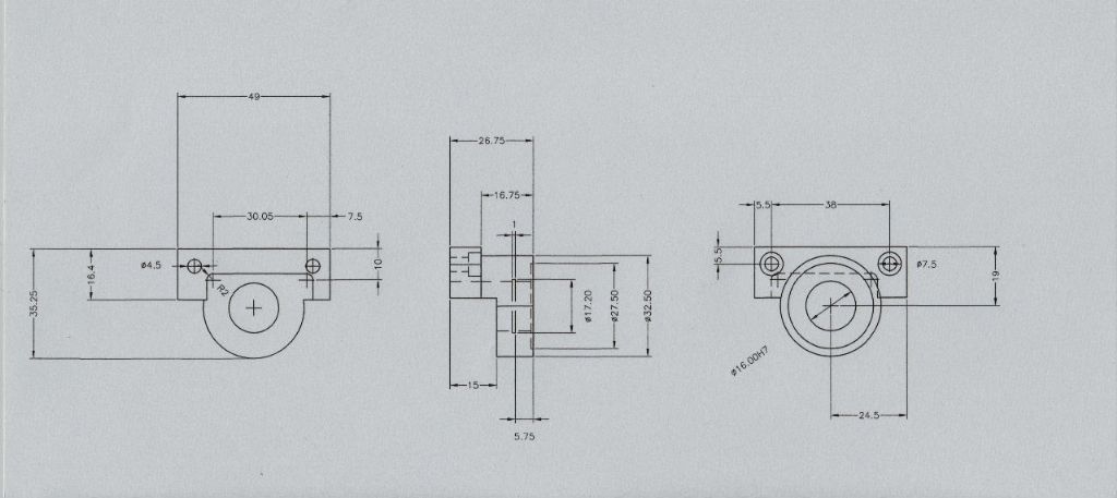
                                              Here is the drawing for the Ball bearing C5 Endplate. To make things simple the bore goes straight through and an internal circlip provides the abutment face for each bearing.

                                              compact 5 endplate.jpg

                                              I hope this has come out OK. If there is a problem perhaps one of the Moderators can upload a PDF which I can do easily.

                                              Regards

                                              Gray,

                                              #607605
                                              Jouke van der Veen
                                              Participant
                                                @joukevanderveen72935

                                                Good morning Gray,

                                                Just another question.

                                                What did you do with the base of the tail stock. Did you make it adjustable or is it a fixed correction of alignment with the head spindle?

                                                Regards

                                                #607627
                                                Graham Meek
                                                Participant
                                                  @grahammeek88282

                                                  Good morning Jouke,

                                                  No problem with questions, it is how we learn things.

                                                  The Lathe was an Old Stock item which had been sitting in a shop for years still boxed. One would have thought it would be in tip-top condition. However the Tailstock alignment was off by quite a bit. I did take the headstock off to see if this had been disturbed in transit but no such luck.

                                                  Correcting the original machined set up was always going to be a problem. If the flat at the rear of the bed is just 0.03 higher than it should be. Then this will throw the tailstock out of alignment both vertically and horizontally, towards the operator. The body pivoting about the front vee way, and of course visa versa.

                                                  Thus in order to get the machine up and running, many years back, I bought a second hand Tailstock. I knew this was never going to be right for the lathe, which it was not, so I went about making a new base and modifying this new Tailstock body.

                                                  The separate base follows any standard Tailstock design with a transverse location tongue to keep things aligned and some form of adjustment to bring the whole on centre line.

                                                  There is a convenient hole in the rear of the body as standard and through this hole I can access two Allen grubscrews. The larger M6 grubscrew is drilled through to allow the Allen key to reach the smaller M5 grubscrew which is in front.

                                                  Both screws are in a large headed pin which is pressed into the new base and sits in a convenient cavity. This Pin protrudes down far enough to engage with a hole in the clamping plate which stops this rotating during movement up the bedway, or during tightening and loosening.

                                                  The M5 impinges on the internal face of the body and moves the whole body towards the Operator. The M6 works on the rear wall of the Tailstock body and takes it in the other direction. This screw is off course turned anti-clockwise to achieve this. Once the machine is turning parallel between centres the two screws are locked by opposing forces.

                                                  One of my next jobs is to rectify the old Tailstock body. Perhaps I will show later on how I go about doing this.

                                                  Hope this helps,

                                                  Regards

                                                  Gray,

                                                  #607628
                                                  Kiwi Bloke
                                                  Participant
                                                    @kiwibloke62605

                                                    Gray, fascinating as ever. Some time ago, I asked whether the Compact 5 should be taken seriously. Clearly, it can be – eventually.

                                                    Emco Holz un Hobby's new saddle looks interesting. Am I right in thinking that it has been threaded as the feedscrew's main 'nut', but also has an adjustable, anti-backlash nut deeper down the feedscrew's bore? It would be nice to have all the female threads easily replaceable.

                                                    [edit – our posts 'crossed'] Now I'm also waiting eagerly for tailstock mod details.

                                                    Now you have a vertical unit for your Unimat, I'm waiting eagerly for your upgrade of the spindle bearings…

                                                    We ask a lot of you, don't we?.

                                                    Edited By Kiwi Bloke on 28/07/2022 11:56:10

                                                    Edited By Kiwi Bloke on 28/07/2022 11:56:32

                                                    Edited By Kiwi Bloke on 28/07/2022 11:57:01

                                                    #607637
                                                    Jouke van der Veen
                                                    Participant
                                                      @joukevanderveen72935

                                                      Hello Gray,

                                                      Thank you for your complete explication of the tailstock modification.

                                                      It looks so simple on the picture on top of this topic but it is not!

                                                      When you rectify the old tailstock body it would be nice, as Kiwi said, to follow all your progress, at least in this topic.

                                                      Kiwi, the thread you see in the carriage is for the hollow “top nut” to compress the adjustable anti-backlash nut behind it. The anti-backlash nut is locked against rotation by an “excentric” hollow pin in the small hole through the carriage. I think you can find this in the Emco C5 manual.

                                                      Regards,

                                                      Jouke

                                                      Edited By Jouke van der Veen on 28/07/2022 13:01:54

                                                    Viewing 25 posts - 1 through 25 (of 82 total)
                                                    • Please log in to reply to this topic. Registering is free and easy using the links on the menu at the top of this page.

                                                    Advert

                                                    Latest Replies

                                                    Home Forums Manual machine tools Topics

                                                    Viewing 25 topics - 1 through 25 (of 25 total)
                                                    Viewing 25 topics - 1 through 25 (of 25 total)

                                                    View full reply list.

                                                    Advert