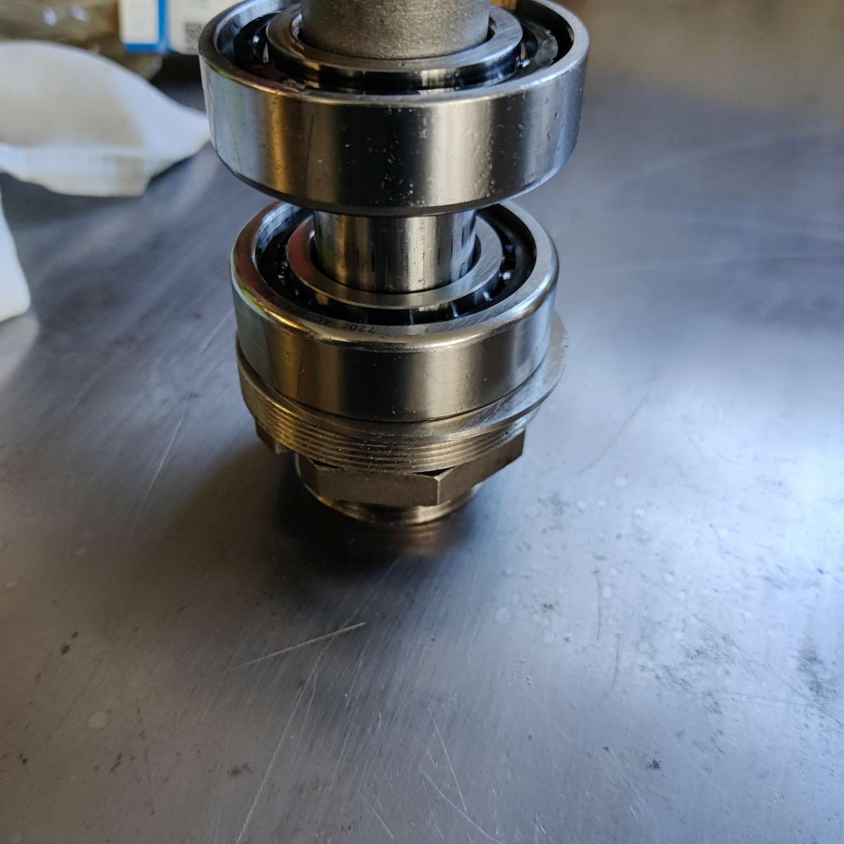
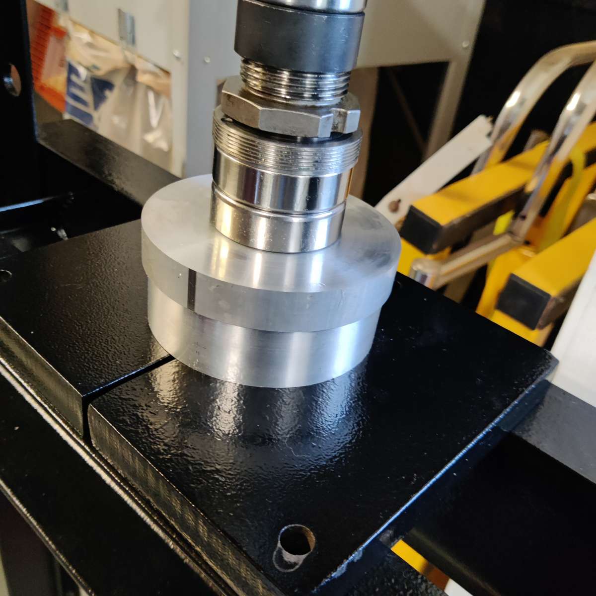
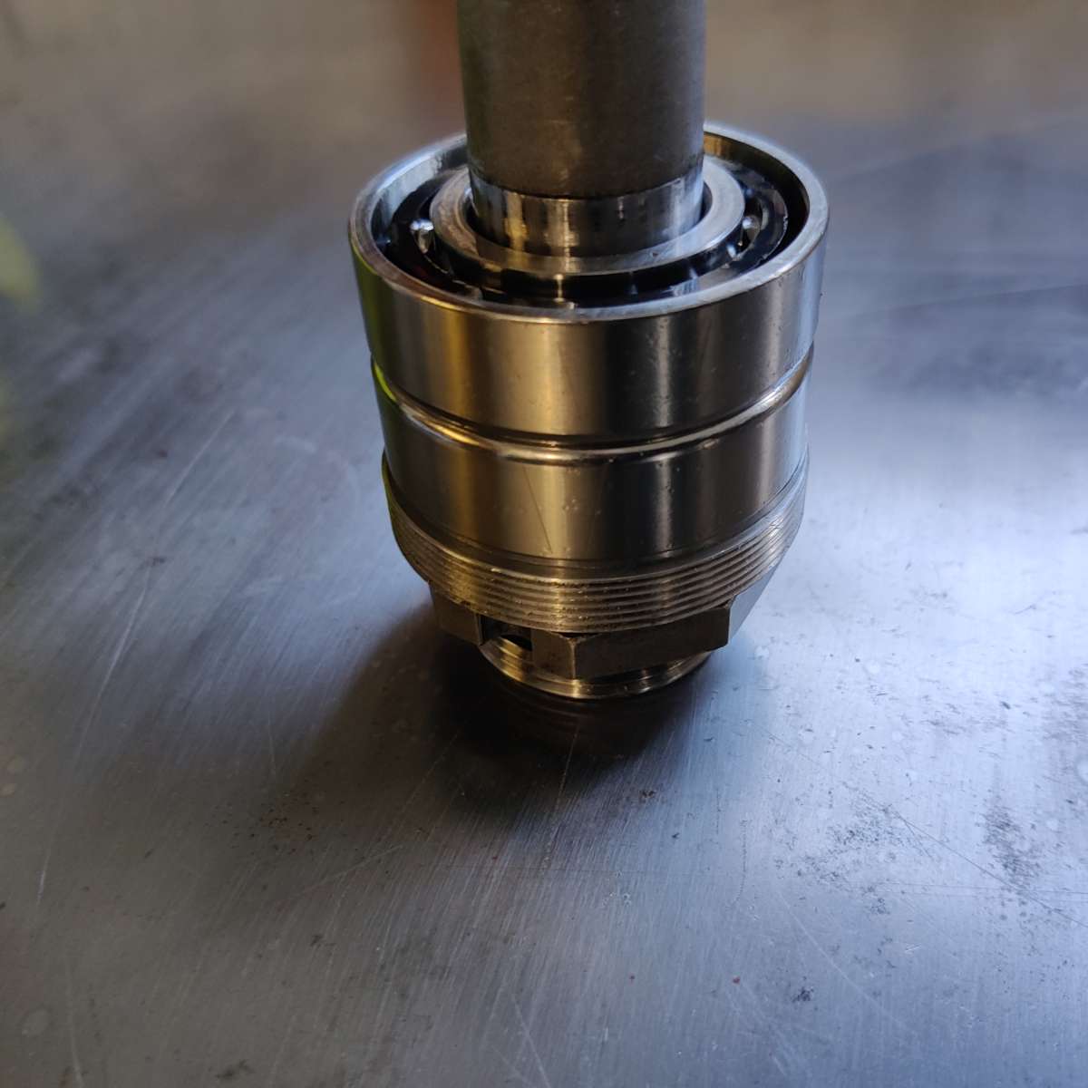
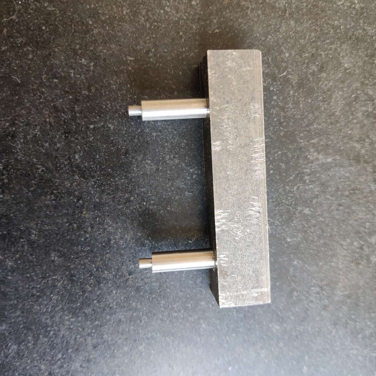
Elliot / Downham jig borer spindle re build
Elliot / Downham jig borer spindle re build
- This topic has 16 replies, 8 voices, and was last updated 27 October 2024 at 13:22 by
bs3750@gmail.com.
- Please log in to reply to this topic. Registering is free and easy using the links on the menu at the top of this page.
Latest Replies
-
- Topic
- Voices
- Last Post
-
-
DIY Pendulum Timer – GPS-Synced Beat Analyser
Started by:
 Chris Raynerd 2
in: Clocks and Scientific Instruments
Chris Raynerd 2
in: Clocks and Scientific Instruments
- 6
-
8 April 2025 at 10:00
Michael Gilligan
-
Steam pressure using thermistor
1
2
Started by:
michael howarth 1
in: General Questions
- 12
-
8 April 2025 at 09:27
duncan webster 1
-
Use horizontal mill as saw for metal?
Started by:
ell81
in: Beginners questions
- 13
-
8 April 2025 at 09:18
Baz
-
Measuring increments on boring head
Started by:
Bill Phinn
in: Workshop Techniques
- 15
-
8 April 2025 at 06:56
JasonB
-
Machinery Handbook
1
2
Started by:
Dalboy
in: Books
- 31
-
8 April 2025 at 03:08
Pete
-
Damp proofing concrete floors
Started by:
Duff Machinist
in: General Questions
- 14
-
7 April 2025 at 21:55
Chris Crew
-
Hammant & Morgan “MINIPACK”
Started by:
Michael Gilligan
in: Electronics in the Workshop
- 3
-
7 April 2025 at 21:46
Michael Gilligan
-
Supply company catalogues
Started by:
nevillet
in: Workshop Tools and Tooling
- 6
-
7 April 2025 at 20:41
vintagengineer
-
Easing out the bore of a 3-jaw, s/c chuck
Started by:
Greensands
in: Workshop Tools and Tooling
- 9
-
7 April 2025 at 19:31
old mart
-
Myford Super 7 restoration problem.
Started by:
Bootlegger Blacky
in: Manual machine tools
- 4
-
7 April 2025 at 19:27
Martin Kyte
-
Ml10
Started by:
keel
in: Beginners questions
- 6
-
7 April 2025 at 18:56
Roderick Jenkins
-
Reader Survey
Started by:
Neil Wyatt
in: Model Engineer & Workshop
- 14
-
7 April 2025 at 18:44
Roderick Jenkins
-
Smart Meters or Not so Smart Companies?
Started by:
Alistair Robertson 1
in: The Tea Room
- 2
-
7 April 2025 at 18:36
Clive Brown 1
-
Morse Key
Started by:
Steve Withnell
in: Work In Progress and completed items
- 5
-
7 April 2025 at 15:40
Steve Withnell
-
Elliott Omnimill Quill Clamp
Started by:
dangermouse
in: Manual machine tools
- 5
-
7 April 2025 at 11:54
dangermouse
-
Chester DB10LB Lathe – Not starting
Started by:
David Deaville
in: General Questions
- 3
-
6 April 2025 at 21:50
Denis O’Kane
-
More Lidl questions
1
2
3
Started by:
old mart
in: Hints And Tips for model engineers
- 26
-
6 April 2025 at 21:06
Nick Wheeler
-
Tangential tooling
1
2
Started by:
Keith Matheson
in: Workshop Tools and Tooling
- 13
-
6 April 2025 at 20:50
Neil Lickfold
-
Flattening brass plates
Started by:
t1krt
in: Workshop Techniques
- 7
-
6 April 2025 at 20:36
old mart
-
How to wire up 3 phase motor and 3 phase converter?
Started by:
ell81
in: Beginners questions
- 8
-
6 April 2025 at 20:17
old mart
-
Problem getting the right parameters on a VFD
Started by:
Robert Graham
in: Electronics in the Workshop
- 8
-
6 April 2025 at 17:19
Dave Halford
-
James Coombes Drawing Error (or mine?)
Started by:
Steve Withnell
in: Drawing Errors and Corrections
- 5
-
6 April 2025 at 15:06
Steve Withnell
-
Which type of single phase motors are best for constant use – power hacksaw
Started by:
ell81
in: Beginners questions
- 5
-
6 April 2025 at 11:44
Clive Foster
-
Stripped aluminum threads. Now what?
1
2
Started by:
brucemc777
in: Beginners questions
- 19
-
6 April 2025 at 10:39
howardb
-
My week this week! My workshop videos
1
2
…
11
12
Started by:
Phil Whitley
in: The Tea Room
- 14
-
5 April 2025 at 16:00
Phil Whitley
-
DIY Pendulum Timer – GPS-Synced Beat Analyser
Latest Issue

Newsletter Sign-up
Latest Replies
- DIY Pendulum Timer – GPS-Synced Beat Analyser
- Steam pressure using thermistor
- Use horizontal mill as saw for metal?
- Measuring increments on boring head
- Machinery Handbook
- Damp proofing concrete floors
- Hammant & Morgan “MINIPACK”
- Supply company catalogues
- Easing out the bore of a 3-jaw, s/c chuck
- Myford Super 7 restoration problem.

