Electronic Lead Screw Project

Advert

Electronic Lead Screw Project

Viewing 25 posts - 126 through 150 (of 285 total)
  • Author
    Posts
  • #448111
    Dennis R
    Participant
      @dennisr

      Dias

      I made top hat buttons with slightly domed heads from a small piece of hard plastic found in my scrap box, they were all made circular. Where Clough42 has triangular buttons mine are a larger diameter, a bit fiddly to do, just make one and try for size then adjust as necessary.

      Dennis

      Advert
      #448112
      Phil Grant
      Participant
        @philgrant54580

        Dias,

        I'm printing the top now , the measurements look the same as mine.

        I'll print some buttons as well.

        Phil

        #448179
        dcosta
        Participant
          @dcosta

          Hi Phil,

          Phil: Here is the link to the box I bought, it is the 1590B version
          Me: Thanks for the link to box 1590B.
          I already ordered it.

          Phil: I'm printing the top now, the measurements look the same as mine. I'll print some buttons as well.
          Me: Thank you very much for this. I am embarrassed because I don't know how to thank you enough. Please read the PM.

          Dias Costa

          #448323
          dcosta
          Participant
            @dcosta

            Hi Jason,

            Thanks for the information.
            Jason: I printed them in flexible material. The files are on the clough42’s thingiverse page.
            Me: I had already found the files from a link in your nice video "Clough42 ELS electronics completed and working." on Youtube.
            From your experience, the buttons made of flexible material do not have much friction with the walls of the holes?

            best regards
            Dias Costa

            #448331
            dcosta
            Participant
              @dcosta

              Hi Dennis,

              Thank you for your attention and suggestion.
              A few weeks ago, before Phil offered me the 3D printed box top, when thinking how I could make the buttons, one of the ways I considered a solution similar to the one you refer to: machining the buttons on the lathe. The other way was to look for buttons and cut them to fit the holes (see here for example: https://www.rubber-keypad.com/Rubber-Button-pl45996.html).
              I could possibly find buttons with the appropriate dimensions, but I suspect that there would be serious friction problems with the hole walls.

              Best regards
              Dias Costa

              #448335
              Jason Cundall
              Participant
                @jasoncundall54270
                Posted by dcosta on 22/01/2020 21:29:40:

                Jason: I printed them in flexible material. The files are on the clough42’s thingiverse page.
                Me: I had already found the files from a link in your nice video "Clough42 ELS electronics completed and working." on Youtube.
                From your experience, the buttons made of flexible material do not have much friction with the walls of the holes?

                None that I can discern. They’re not a tight fit in the holes.

                #449334
                Roger Clark
                Participant
                  @rogerclark

                  So I wanted to 3d print the lid but wanted to customise it to my requirements, to this end I downloaded Fusion 360 as it's a product that I wanted to learn so I loaded up the STEP file for the lid and over yesterday pm and this evening I worked out that svg files were the way to go so downloaded Inkscape and learned how to create svg files from text and here is the result:

                  control_panel_lid v5.jpg

                  I'm happy with it but haven't tried printing it yet, not bad for a 68 year old! devilwink

                  Roger

                  #449339
                  SillyOldDuffer
                  Moderator
                    @sillyoldduffer
                    Posted by Rockingdodge on 27/01/2020 20:17:19:

                    So I wanted to 3d print the lid but wanted to customise it to my requirements, to this end I downloaded Fusion 360 as it's a product that I wanted to learn so I loaded up the STEP file for the lid and over yesterday pm and this evening I worked out that svg files were the way to go so downloaded Inkscape and learned how to create svg files from text and here is the result:

                    control_panel_lid v5.jpg

                    I'm happy with it but haven't tried printing it yet, not bad for a 68 year old! devilwink

                    Roger

                    Brilliant!!!

                    I've been struggling to do similar. Been getting mixed results from outputting STL from Inkscape and manipulating it with 3 or 4 different packages. I shall kick myself if the answer is to work directly from SVG.

                    Well done you!

                    Dave

                    #449344
                    Phil Grant
                    Participant
                      @philgrant54580
                      Posted by Rockingdodge on 27/01/2020 20:17:19:

                      So I wanted to 3d print the lid but wanted to customise it to my requirements, to this end I downloaded Fusion 360 as it's a product that I wanted to learn so I loaded up the STEP file for the lid and over yesterday pm and this evening I worked out that svg files were the way to go so downloaded Inkscape and learned how to create svg files from text and here is the result:

                      I'm happy with it but haven't tried printing it yet, not bad for a 68 year old! devilwink

                      Roger

                      I did the same thing on my 3D printed lid in fusion 360 but when I printed it the text didn't come out to well, print it with the smallest layer height you can but it will take a lot longer to print.

                      #449353
                      Roger Clark
                      Participant
                        @rogerclark
                        Posted by Phil Grant on 27/01/2020 21:00:10:

                        Posted by Rockingdodge on 27/01/2020 20:17:19:

                        So I wanted to 3d print the lid but wanted to customise it to my requirements, to this end I downloaded Fusion 360 as it's a product that I wanted to learn so I loaded up the STEP file for the lid and over yesterday pm and this evening I worked out that svg files were the way to go so downloaded Inkscape and learned how to create svg files from text and here is the result:

                        I'm happy with it but haven't tried printing it yet, not bad for a 68 year old! devilwink

                        Roger

                        I did the same thing on my 3D printed lid in fusion 360 but when I printed it the text didn't come out to well, print it with the smallest layer height you can but it will take a lot longer to print.

                        Hi Phil,

                        I bought myself a resin printer so hoping that I can get good results on the fine detail.

                        Got priorities at the moment like re-assembling my mini lathe after stripping the teeth on the drive pulley, I also decided as it's in bits I'll fit dro as well so got that to do before anything else.

                        Roger

                        #449356
                        Roger Clark
                        Participant
                          @rogerclark
                          Posted by SillyOldDuffer on 27/01/2020 20:44:57:

                          Posted by Rockingdodge on 27/01/2020 20:17:19:

                          So I wanted to 3d print the lid but wanted to customise it to my requirements, to this end I downloaded Fusion 360 as it's a product that I wanted to learn so I loaded up the STEP file for the lid and over yesterday pm and this evening I worked out that svg files were the way to go so downloaded Inkscape and learned how to create svg files from text and here is the result:

                          control_panel_lid v5.jpg

                          I'm happy with it but haven't tried printing it yet, not bad for a 68 year old! devilwink

                          Roger

                          Brilliant!!!

                          I've been struggling to do similar. Been getting mixed results from outputting STL from Inkscape and manipulating it with 3 or 4 different packages. I shall kick myself if the answer is to work directly from SVG.

                          Well done you!

                          Dave

                          Hi Dave,

                          If you use Fusion 360 you can 'INSERT' svg file and then 'Extrude' either up for emboss or down '-' as I did.

                          This was the first time I'd used CAD, simples devil, just had to deal with sky high frustration levels sad

                          Roger

                          #449374
                          Phil Grant
                          Participant
                            @philgrant54580
                            Posted by Rockingdodge on 27/01/2020 21:27:35:

                            Hi Dave,

                            If you use Fusion 360 you can 'INSERT' svg file and then 'Extrude' either up for emboss or down '-' as I did.

                            This was the first time I'd used CAD, simples devil, just had to deal with sky high frustration levels sad

                            Roger

                            Roger,

                            I've been using Fusion360 for a couple of years and I never new you could do that surprise every day is a school day thanks for the tip.

                            I spent ages inserting and placing the text on the front surface sad.

                            Phil

                            #449378
                            Phil Grant
                            Participant
                              @philgrant54580
                              Posted by Rockingdodge on 27/01/2020 21:23:11:

                              Hi Phil,

                              I bought myself a resin printer so hoping that I can get good results on the fine detail.

                              Got priorities at the moment like re-assembling my mini lathe after stripping the teeth on the drive pulley, I also decided as it's in bits I'll fit dro as well so got that to do before anything else.

                              Roger

                              Roger,

                              You should be fine with a resin printer the resolution should be more than enough, my Ender3 struggled with the small text above the LEDs.

                              Phil

                              #449426
                              Roger Clark
                              Participant
                                @rogerclark

                                Just found this Adafruit tutorial on creating a box, I found it easier to pick up than some of the others, lots of ways of stringing dimensions together to make adjusting easier. Adafruit snap fit cases

                                Roger

                                #449448
                                SillyOldDuffer
                                Moderator
                                  @sillyoldduffer
                                  Posted by Phil Grant on 27/01/2020 22:29:13:

                                  Posted by Rockingdodge on 27/01/2020 21:27:35:

                                  Hi Dave,

                                  If you use Fusion 360 you can 'INSERT' svg file and then 'Extrude' either up for emboss or down '-' as I did.

                                  This was the first time I'd used CAD, simples devil, just had to deal with sky high frustration levels sad

                                  Roger

                                  Roger,

                                  I've been using Fusion360 for a couple of years and I never new you could do that surprise every day is a school day thanks for the tip.

                                  I spent ages inserting and placing the text on the front surface sad.

                                  Phil

                                  Me neither; I'm moderately fluent in both Inkscape and Fusion and hadn't spotted that, despite looking! (I must have wasted a full week investigating alternatives that don't quite fly. Arghh!)

                                  Ideally Fusion would be as good at text as Inkscape, but it only does the basics. Inkscape has many excellent features, but it's not a CAD tool. Nice to know there's a way of getting the two to work together!

                                  Ta

                                  Dave

                                  #451299
                                  dcosta
                                  Participant
                                    @dcosta

                                    Hi Phil,

                                    I thank you very much for the great favor of printing for me, in 3D, the cover and the buttons for the control box of the "Electronic Lead Screw".
                                    I've already done a temporary assembly of the cover with the Led & Key Display (L&KD) and the adjustment between the L&KD and the cover is good and the buttons work very well.
                                    To complete this part of the project, I still need to receive the metal box, which comes from China with an estimated arrival between 11 and 20 February, but, probably given the current circumstances, it will take longer to arrive. For this reason, I looked better here, in Portugal, and found the Hammond 1590B box and already ordered it.

                                    Questions:
                                    1 – the first button from the left (PWR) at this moment has no function. Do you know if there is any future goal for him in the project?
                                    2 – How did you write the text FWR FWD / REV FEED / THR MM / IN / TPI given the scarcity of space above the LEDs? Any suggestions, please …
                                    3 – I already have the stepper motor (Nema 23, double shaft purchased from ArcEuroTrade a few years ago) and I want to use it in this project for my EMCO Compact 8 lathe.
                                    But I still haven't bought the driver for the stepper motor and, not being interested in the closed loop stepper driver, I'm not sure to choose another controller. As previously reported I tried the TB6560 driver and somehow damaged the TI board and I don't want to repeat …
                                    Any suggestion, please?

                                    Best Regards
                                    Dias Costa

                                    Edited By dcosta on 08/02/2020 18:56:59

                                    #451320
                                    Phil Grant
                                    Participant
                                      @philgrant54580

                                      Dias,

                                      You're Welcome.

                                      Answers o your questions: –

                                      1. I'm not sure, other than power everything up on the bench I've not yet had it connected to my lathe properly, I would suggest a visit to Clough42s GIT page and ask the question there.

                                      2. sad I haven't yet see answer No. 1. I was thinking of using a Dymo type printer and varnish over the top of the label.

                                      3. I also have a NEMA23 double shaft I bought from steppersonline, I also bought a DM542T controller Digital Controller I believe they are smoother than the cheaper Chinese non DSP controllers.

                                      I hope that helps, I know it's probably the answers you were hoping for.

                                      Phil

                                      #452372
                                      dcosta
                                      Participant
                                        @dcosta

                                        Hi Phil,
                                        I have already assembled the cover you offered on the box I bought from England. It fits well but only after cutting the small curved edge at the corners. My box is therefore different from yours. Interestingly, the day after the assembly of the lid you offered me, the box ordered from China arrived and I could verify that the lid is exactly the same as the one I bought here in Portugal.
                                        So, I have this part of the project almost ready.

                                        I didn't find on the WWW anyone who sold the driver DM542T to Portugal and that's why I bought the DM542. Whatever the differences, I'm not sure, but I read that basically, for my purpose, they are the same. Later, eventually, when the COVID-19 crisis is over, I can buy the DM542T.
                                        I want to go ahead and make the connections to the PCB interface you made.
                                        I now need help with the following: The interface you manufactured, has connections that are visually different from those of the Clough interface and also the driver that I have has different connection point designations than the driver that Clough uses. So I can't use the diagram he makes available to support the connections.
                                        Could you please show me the point-to-point connections between the interface board and the DM542T driver?

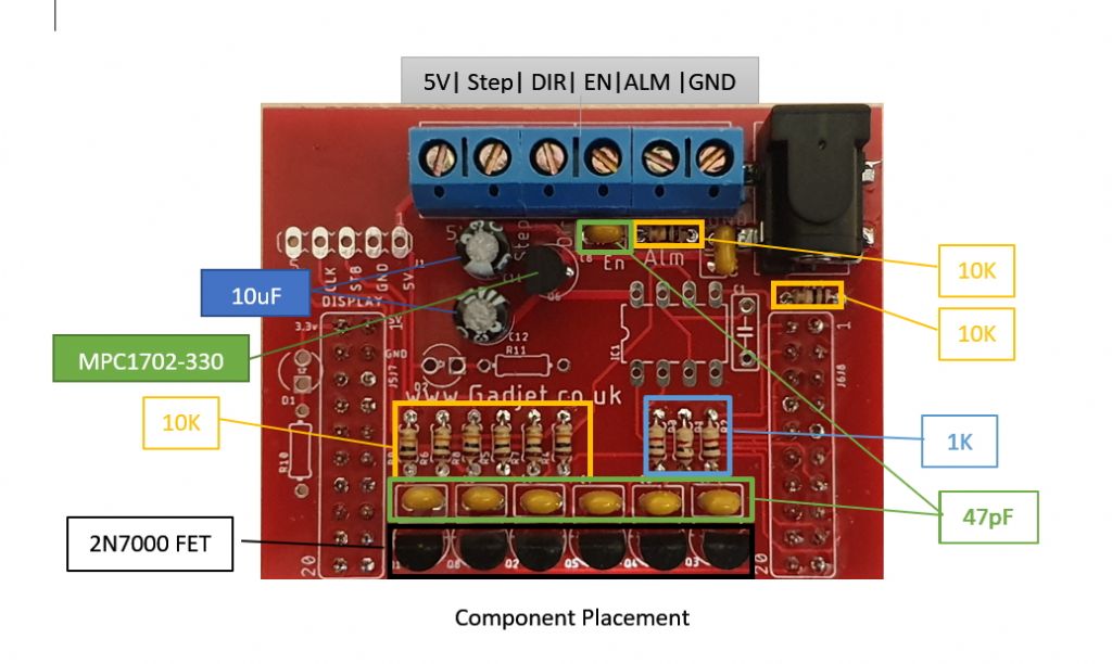
                                        Can you tell me, please, what does ALM mean? I looked in acronym finder but I didn't find an answer that fit.

                                        Thanks in advance
                                        Dias Costa


                                        #452374
                                        Limpet
                                        Participant
                                          @limpet

                                          Hi Dias

                                          I can answer one of your questions ALM would be for Alarm both + and –

                                          Lionel

                                          #452408
                                          Phil Grant
                                          Participant
                                            @philgrant54580

                                            Hi Dias,

                                            There is a pinout diagram in the other thread and a link to a document I put together tho show how it is assembled, does this pinout help?

                                            screw terminal connections.jpg

                                            As far as I know the ALM (Alarm) is a signal that comes from t and if you use a stepper it's not used anyway.he servo controller when there is something wrong like missed steps etc. the last I read it wasn't implemented yet.

                                            I hope that helps.

                                            Phil

                                            #452419
                                            dcosta
                                            Participant
                                              @dcosta

                                              Hello Limpet.

                                              I really appreciate your help.
                                              For someone like me who is a "turnip" in electronics and does not have English as his native language, it is sometimes difficult to discover the meaning of some words, especially if contained in idiomatic expressions, let alone acronyms!

                                              Best regards
                                              Dias Costa

                                              #452422
                                              dcosta
                                              Participant
                                                @dcosta

                                                Hi Phil,

                                                I really appreciate your quick help.
                                                Please consider the wiring diagram for the DM542 interface driver, ***HERE*** .
                                                Which interface pin do I connect to VCC? It seems to me that it should be the positive 5V output. Am I right?
                                                I assume that Pulse should be connected to Step, Direction should be connected to DIR and Enable should be connected to EN.
                                                What about the negative pole? Can I understand that it is passed by each of the STEP, DIR and EN? And so, in addition to ALM, do I also ignore GND?

                                                Thanks and regards
                                                Dias Costa

                                                #452426
                                                Roy Vaughn
                                                Participant
                                                  @royvaughn26060

                                                  Dias, connect +5V to the + terminals of each signal as shown in the wiring diagram. Yes, ignore GND from the interface board. Hope this helps. Roy

                                                  #452428
                                                  Phil Grant
                                                  Participant
                                                    @philgrant54580
                                                    Posted by dcosta on 15/02/2020 21:58:06:

                                                    Hi Phil,

                                                    I really appreciate your quick help.
                                                    Please consider the wiring diagram for the DM542 interface driver, ***HERE*** .
                                                    Which interface pin do I connect to VCC? It seems to me that it should be the positive 5V output. Am I right?
                                                    I assume that Pulse should be connected to Step, Direction should be connected to DIR and Enable should be connected to EN.
                                                    What about the negative pole? Can I understand that it is passed by each of the STEP, DIR and EN? And so, in addition to ALM, do I also ignore GND?

                                                    Thanks and regards
                                                    Dias Costa

                                                    Dias,

                                                    As Roy says, VCC == +5V, the others are as you said. Clough42 recommends that the power for the stepper driver and the electronics remain seperate so do not connect the grounds together, the 5V and GND from the PCB should only be used to power the optocouplers in the driver.

                                                    Phil

                                                    #452434
                                                    dcosta
                                                    Participant
                                                      @dcosta

                                                      Hi Phil,
                                                      Hi Limpet,

                                                      I really appreciate your quick help.
                                                      There was a "disgrace" …
                                                      Is there a way to test the integrity of the TI LaunchXL F280049C?
                                                      I think I just burned one more, the second.
                                                      I connected the DM542 driver to the interface, as suggested, and when I powered on the interface, the display showed nothing. The DM542 driver was not connected.
                                                      As it is the second I burn in similar circumstances, I must have made some mistake in the interface.
                                                      The two serial ports that the "Code Composer Studio" software uses to communicate with the F280049C are no longer present in device management as they did when I burned the first board.

                                                      Thanks and regards
                                                      Dias Costa

                                                      Edited By dcosta on 15/02/2020 23:25:06

                                                    Viewing 25 posts - 126 through 150 (of 285 total)
                                                    • Please log in to reply to this topic. Registering is free and easy using the links on the menu at the top of this page.

                                                    Advert

                                                    Latest Replies

                                                    Viewing 25 topics - 1 through 25 (of 25 total)
                                                    Viewing 25 topics - 1 through 25 (of 25 total)

                                                    View full reply list.

                                                    Advert

                                                    Newsletter Sign-up