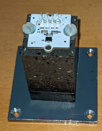
I have been following Carl Wilson's article in ME on an "Electronic Hipp Toggle Circuit" with the idea of using it with some modifications. I plan on using Hall effect devices vice opto interrupters. This will require some changes to the logic as the output of the Hall devices is high in the unenergized state whereas the opto ones are low but I haven't decided how I will implement it yet.
In going through the schematic, the block diagram and description of the logic flow, unless I am misinterpreting something, it seems to me there is are some errors in the schematic as drawn as it doesn't agree with the block diagram and the logic description.
The way the schematic is drawn the outputs of the three flip flops appear to be backwards. The output of the "MIN" F/F is shown as the "Q" output but the block dia. and description both show it as the "NOT Q" output. Same for the ENA and ON F/Fs both shown as "NOT Q" where a the block dia. and description show both as the "Q" output. (The ON F/F does show the output labeled as "Q" but is in the position of the "NOT Q" output )
The description and the block diagram appear to agree.
John
Edited By John Purdy on 31/10/2022 02:50:23
Edited By John Purdy on 31/10/2022 02:54:39
John Haine.


