Would I be right in thinking that for most of the fastenings i.e. setscrews/nuts etc in a traction engine build they need to be the one size smaller head type..?
Depends on what you are using, commercial metric can often look too large across flats and too flat so I would use smaller heads to look more in keeping with the original. BA should be OK if they are decent machined heads and nuts, again some of the cheaper forged ones are flat and not that well formed.
Thanks Jason, I have a selection of BA taps and some dies so will probably go with BA where I can. I think GLR Kennions do a reasonable range of the small head type.
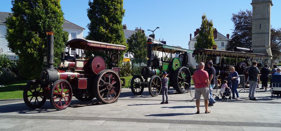
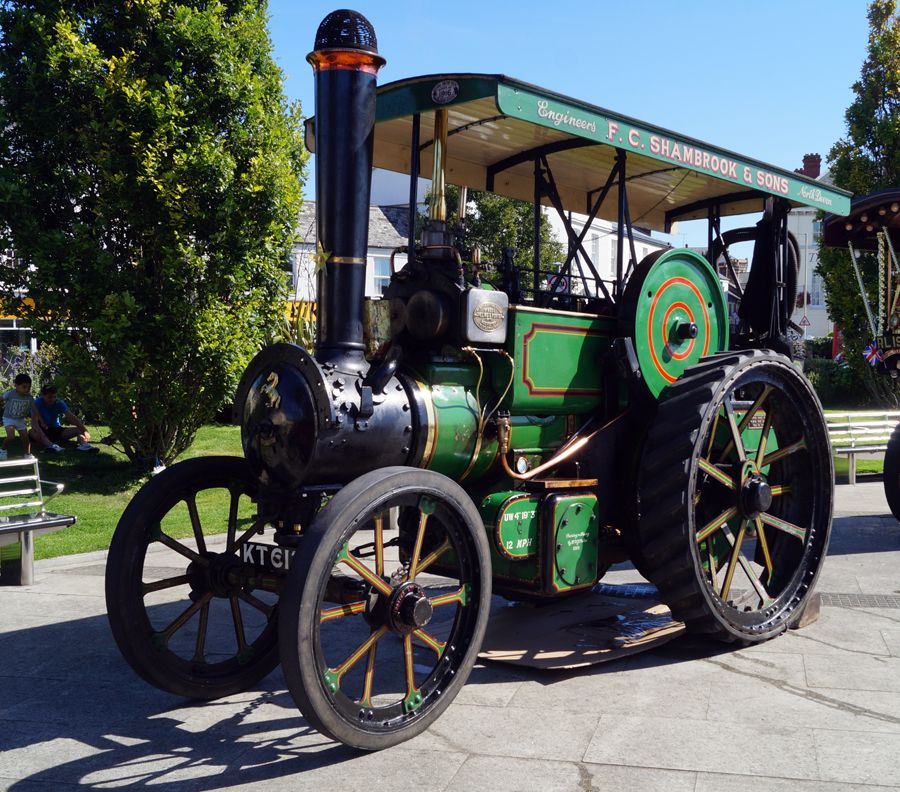
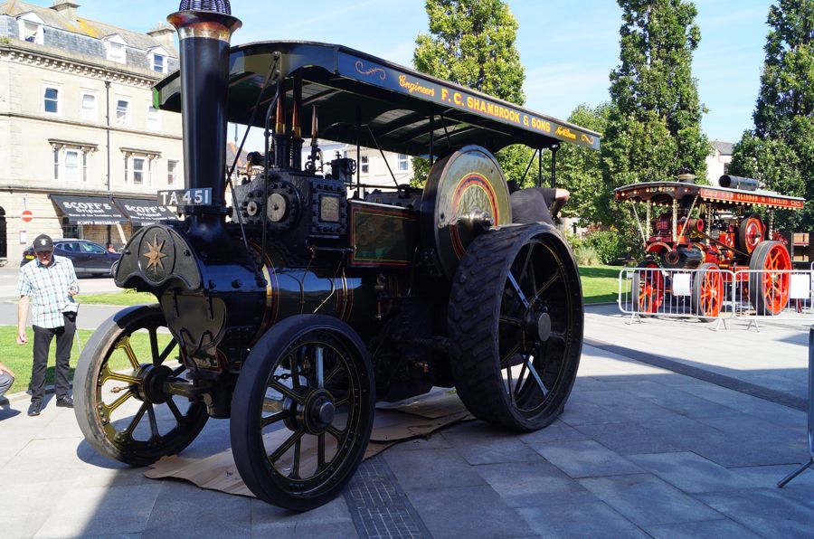
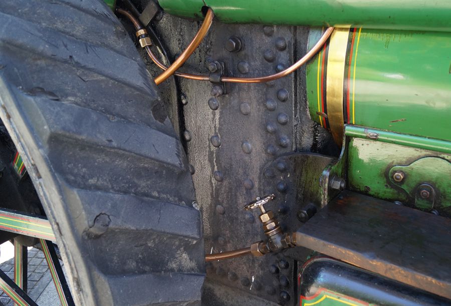
Look what I found in Barnstaple town square this morning, there was five full size and two 4 inch so I dashed home grabbed the camera and managed to take dozens of close detail shots which should be helpful.
Lucky find Ron – interesting tyre treatments too – the red engine has what looks like the usual two circular rubber ribs, the Aveling has what looks like rubber strakes and the last one has apparently the central tread section of an I/C tractor tyre !
DaveD
I had a test run this morning in producing a pair of half bearings for the crankpin, reading the Minnie instructions I think it it suggests soft soldering the two halves together, machine and then melt apart.
I thought of giving it a try another way so I cut a piece of brass down the centre using a 1.0 mm slitting saw which leaves to clean faces and then put them together and set them up in the 4 jaw with a good 20 mm in the jaws to hold it together. Faced the end and then drilled and reamed for a good fit to the pin, I drilled for the reaming size in a number of steps as I was worried to heavy and the two halves may spread. Turned the rest of bearing and then cut them off and faced the cut end in the 3 jaw.
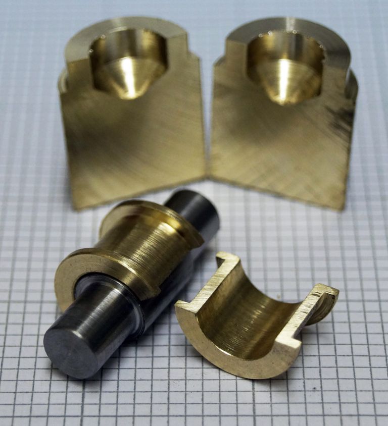
Seems to have worked quite well, picture below shows the two halves of bar they came from. Would brass work in this application, it is a lubricated bearing and its just that the pair are a really nice fit to the pin. If not I will get hold of some bronze.
Lucky find Ron – interesting tyre treatments too – the red engine has what looks like the usual two circular rubber ribs, the Aveling has what looks like rubber strakes and the last one has apparently the central tread section of an I/C tractor tyre !
DaveD
Dave, I also heard one of the engine owners explaining to someone that the Burrell in the last picture can be converted into a steam roller by removing and changing the wheels, quite impressive I thought.
There is also the option to do the Minnie as a convertible if you have a few minutes to spare Ron
Thanks Jason, I didnt realise that the Minnie had been done as a roller but why not, though I think the engines with the standard wheels are a bit more handsome.
Would you have any thoughts on me using the brass half bearings, as I mentioned they are a nice fit but I can easily reproduce them in bronze, would appreciate your opinion.
I had a test run this morning in producing a pair of half bearings for the crankpin, reading the Minnie instructions I think it it suggests soft soldering the two halves together, machine and then melt apart.
I thought of giving it a try another way so I cut a piece of brass down the centre using a 1.0 mm slitting saw
…
Would brass work in this application, it is a lubricated bearing and its just that the pair are a really nice fit to the pin. If not I will get hold of some bronze.
I think so, but it depends on the service. Brass alloys make a reasonably good bearing material even though they're not quite as hard wearing or slippery as a bearing Bronze. So Brass is an OK choice when the amount of wear and loadings are low, or if the shells/bushings are easy to replace when worn out. Not so smart using Brass if the crankpin will be worked hard and the shells are difficult to replace. In that case Bronze is the better option.
Although Bronze is harder, less malleable, less likely to crack and has a lower coefficient of friction than Brass, it's also harder to machine. Let's be honest, Bronze can be a pig. Therefore, making engines for private fun I much prefer Brass, but I'd consider Bronze bearings if a friend wanted to buy one for regular running.
Ron as your crank is only doing decorative work moving a piston rod I can't see much of an issue with using brass, even if after a period of use you can just tighten it up a bit should a knock develop.
I quite like machining bronze and use it on all my little ( and large ones too) engines for bearings as well as things like fabricated cylinder preferring 660 and only using other grades for very small stuff where it is wasteful to cut from the smallest available 660 stock. It is possibly nicer to work than brass.
No replies yet? Must all be too busy counting them
I have done both for all the size rivits that I have used. For easy to get at ones you can hold one commercial snap upright in a vice to take the factory head and then use a second to form the head from above.
The problem comes (quite often on a TE) when you can't get a stock rivit snap in where you need it such as when doing the rear spokes or inside the tender. In these cases I have made short snaps from silver steel that have a small spigot behind the head that can be placed in holes drilled into various bits of metal to support them. The recess can either be made with a suitable size ball ended milling cutter, home made "d" bit or heat the rough shaped part sand stand a ball bearing in the recess and give it a whack with a big hammer this last one did not work for me.
You may also find that even with shop bought ones that they are a bit bulky and may need the end turning down, they are hardened but I have done it with Carbide tooling. even then when working close to the fillets around the tee rings you may have to grind a little extra away.
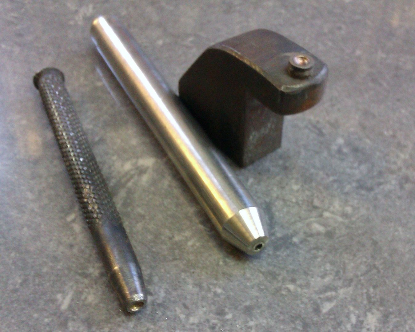
Rivit sets can be made as they are just a hollow punch drilled to fit over the rivit shank, don't really need to be hardened.
Photobucket is a bit slow at the moment will post photos later
A small shop bought one, homemade set and a snap in a holder
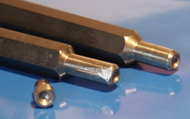
The hex snaps are shop bought, larger ones turned to a parallel end rather than tapered like the others and some have had one side ground for clearance, another snap in a bar to hold it and the and finally a snap that went into a 12" long rod to access rivits inside a tender.
Close up of the modified snaps and a small one with side also ground away.
Thanks for the pictures Jason, I can see that you can soon build up a collection as jobs dictate. I have never done any riveting mind so some practice will be needed, although the horn plates wont be fixed by rivets I am going to add a good number. I took a number of pictures from the full size engines at the weekend so can work out a layout from those.
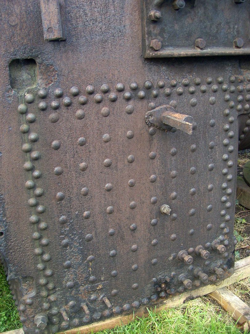
The stays tie the 5 sides of the inner firebox to the outside plates leaving a water space between. In full size a long tap is used to tap the two holes and then threaded stays screwed in with a little left sticking out each side. these are then "rivited over" to form a head which is generally flatter than a standard rivit more just peined over.
Where the side plates join the throat plate, backhead and top of the boiler barrel you usually get the staggered double row of rivits. At the bottom a single row is used that go through outer plate, foundation ring and firebox.
This facebook album shows a smaller portable boiler being built which should give you an idea of how a boiler goes together
Thanks for the link Jason, quite fascinating seeing how one goes together, more to it than I imagined.
Yet another question..sorry
When calculating the gear positions and centres is it best to stick to the gear PCD,s or increase the centres between gears by a few thou to prevent any tight spots. I obviously dont mean having sloppy gears but just enough to allow free running and not having an issue later in the build.
A lot of commercial gears will be sized to allow a small amount of backlash when positioned with the calculated PCD distances.
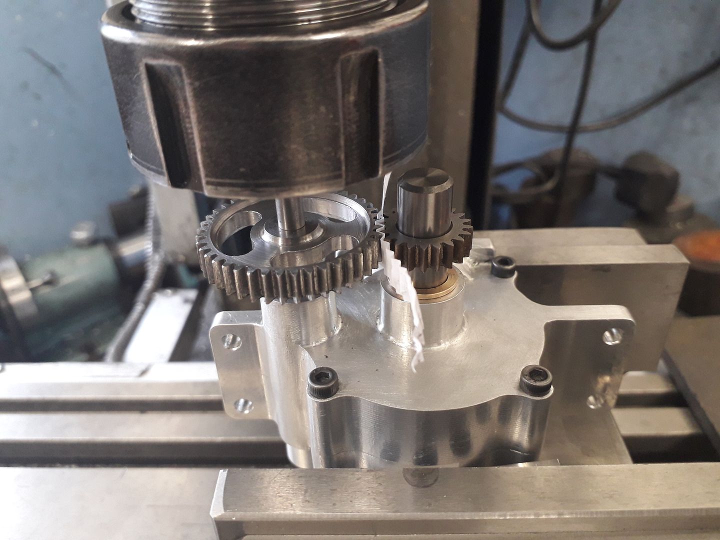
Whether cut myself or bought I prefer where possible to use the actual gears to set the position on the work, if you can't do this then you can check measurements with the gears laid on a flat surface with good fitting pins in the holes, a slither of paper between teeth and then measure over the pins and deduct half the dia of each to check the distance.
To "fit" them on the actual part the first hole is done, a pin put into the hole and the gear slipped onto that. Then the other gear is positioned onto a pin held in a collet and the mill table position tweaked while rotating the gears by hand to get a good fit again with a strip of paper to set some backlash, fag paper for small gers upto photo copy paper for your size. When happy with position lock the table and/or zero the DRO.
And you can always check the fit afterwards whole still in the machine
Looking back at my weekend pictures, I didnt notice at the time but although the Aveling was tyred with rubber strakes is that metal strakes I can see on the rim below..? I think it probably is.