Electric Traction Engine

Advert

Electric Traction Engine

Home Forums Miscellaneous models Electric Traction Engine

Viewing 25 posts - 151 through 175 (of 277 total)
  • Author
    Posts
  • #427815
    JasonB
    Moderator
      @jasonb

      Ron, to save some cost you could do the fronts from ERW tube, have a look at this post of mine which may help with making and soldering. Old Gas bottle may get you close to the rear size you want.

      Advert
      #427823
      Ron Laden
      Participant
        @ronladen17547

        Thanks Paul/Jason thats very helpful.

        I have just checked and I can buy a short length of 6 inch O/D – 10swg steel tube from my usual supplier so that will cover the front rims. Thanks for the link to your wheel making Jason, I thought that quite ingenious the way you produced them, very clever actually.

        I will start having a search around for the size of gas bottles to see if any are near 9.5 inches.

        Thanks again guys.

        #427868
        Ron Laden
        Participant
          @ronladen17547

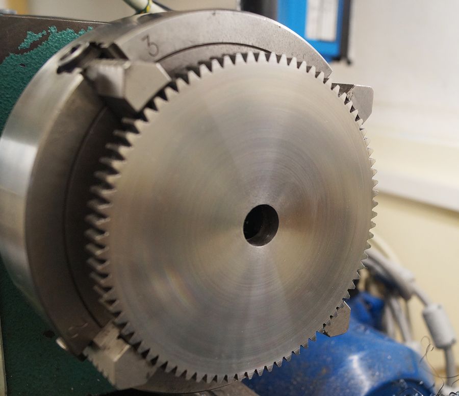
          Reduced the large gear from 15mm to 10mm, 80T – 1.5 MOD getting towards 5 inch diameter, I put it up on the lathe as I didnt fancy fly cutting it in 2 passes. I dont know what it is made from, some Chinese concoction but it was awful to machine, really hard work and the hardened teeth didnt help, I wouldnt be in a hurry to do another one.

          HSS wouldnt look at it and the insert tool didnt think much of it either, 10 thou cuts was the most I could go with and that was pushing it. Finish is not perfect but quite smooth to the finger so I think it will do. I now have 160 hardened teeth ends to debur and a standard needle file wont have it so probably need to get a couple of diamond type.

          I have noticed that the last 20mm towards the centre hasnt cut so well but I suspect that was lack of speed. I increased the speed as the diameter of the cut reduced but I was in mid speed range which was probably not enough for the centre. I will wind the speed up later and see if a light finishing cut improves it.

          dsc06957.jpg

          Edited By Ron Laden on 07/09/2019 09:51:00

          Edited By Ron Laden on 07/09/2019 09:56:31

          #427910
          Ron Laden
          Participant
            @ronladen17547

            The mid range speed (up to 930 rpm) which I used for most of the machining covered the outer half of the gear but not the inner. I dialled it up to 1600 rpm and gave it a light finishing cut and it looks to have a marked improvement.

            dsc06962.jpg

            #427913
            JasonB
            Moderator
              @jasonb

              Ron, to be able to harden the steel it would need a higher carbon content than mild steel and that makes it less easy to machine where ever in the world it may come from. Looks like you got a good finish in the end.

              #427914
              Ron Laden
              Participant
                @ronladen17547
                Posted by JasonB on 07/09/2019 15:41:39:

                Ron, to be able to harden the steel it would need a higher carbon content than mild steel and that makes it less easy to machine where ever in the world it may come from. Looks like you got a good finish in the end.

                Thats a good point Jason, thanks.

                #428007
                Ron Laden
                Participant
                  @ronladen17547

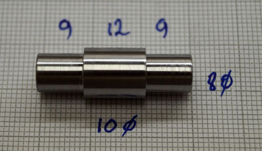
                  I was using some 10mm ground bar so a good opportunity to turn the crankpin, I am thinking of assembling the pin, shaft and webs with 638 retainer and then cutting the crank out between the webs. I am assuming with this method the assy also needs pinning..?

                  dsc06969.jpg

                  #428010
                  Michael Gilligan
                  Participant
                    @michaelgilligan61133

                    If Loctite 638 is used properly, I can see no point in pinning the assembly.

                    Others may have a different view; so let me ask: What purpose would it serve ?

                    MichaelG.

                    #428011
                    Ron Laden
                    Participant
                      @ronladen17547

                      Michael, I was just thinking that the pins would prevent any possibility of the parts working loose but I must admit I have every confidence in 638, the wheels on my locos are fitted to the axles with 638 and nothing else. I wondered what the norm is with this method of building a crankshaft and what other people do.

                      Ron

                      Edited By Ron Laden on 08/09/2019 09:31:30

                      #428013
                      Michael Gilligan
                      Participant
                        @michaelgilligan61133

                        In my view, Ron

                        If the pins were 'called-upon' to do anything; then the 638 must have already failed.

                        … Let's see what the others have to say.

                        MichaelG.

                        #428015
                        Ron Laden
                        Participant
                          @ronladen17547
                          Posted by Michael Gilligan on 08/09/2019 09:40:54:

                          In my view, Ron

                          If the pins were 'called-upon' to do anything; then the 638 must have already failed.

                          … Let's see what the others have to say.

                          MichaelG.

                          I also wondered is the main purpose of the 638 an assembly adhesive for fitting/aligning the parts which are then pinned, I dont know..?

                          #428023
                          JasonB
                          Moderator
                            @jasonb

                            For me it depends on the loads the crank is going to get. On the small 24mm bore engines I have been doing which will just run gently on air I'm happy to just go with Loctite usually 648 in my case.

                            For a larger engine then I'll add pins so that should the loctite fail the crank will hopefully still stay solid, I have read of cranks slipping too many times on model forums. hard to tell if the failure was due to the Loctite or the user but for the sake of a couple of holes, some rod and a hammer to pein the ends over I would add them.

                            On the hit and miss engines that have a far more violent kick when they fire I prefer to silver solder & pin after soldering for the made up ones or just cut from solid. Small IC aero engines I cut from solid.

                            My Minnie is silver soldered, the 2" Fowler machined from an SG Iron casting.

                            #428077
                            Ron Laden
                            Participant
                              @ronladen17547

                              Thanks Jason, mine of course should be lightly loaded as the drive will be coming back through the gears from the motor so to speak but there is still a flywheel connected and as you once mentioned the crank and 2nd shaft gears could be fair whizzing around. I think I will go belt and braces and pin it, as you say its not much effort to do.

                              I would be interested in your thoughts on machining a flywheel from solid, it would be a new challenge for me but I have been giving some thought to how I would go about it. The flywheel is 6" x 13/16" or as near as and I can get a 6 inch round of cast iron, cost is £35 though and to be honest I havnt yet searched for a suitable casting, price or availability wise. I know you have machined them from solid and would be interested in your experience of making them.

                              Ron

                              #428174
                              Ron Laden
                              Participant
                                @ronladen17547

                                I wouldnt have thought the material spec for the crankshaft is crucial, I am copying the Minnie crank and I dont think material type is mentioned other than steel. I am going with what I have which is EN1A ground bar 10mm for the pin and 12mm for the shaft and EN1A bar for the webs which at my scale are 56mm diameter, think it should be ok.

                                #428182
                                JasonB
                                Moderator
                                  @jasonb

                                  Ron, are you going for a solid disc type flywheel as seen on road Locos and showmans engines or will you be wanting to carve out spokes?

                                  ENIA will be fine for your crank given as it is really only decorative and only has to support the flywheel and move a dummy piston.

                                  #428185
                                  Ron Laden
                                  Participant
                                    @ronladen17547

                                    Jason, I was thinking of going with a six spoke wheel most of which I would machine on the lathe and then to the RT for cutting out the spokes..?

                                    #428240
                                    Ron Laden
                                    Participant
                                      @ronladen17547

                                      I said I learn something everyday smiley, in the build of the Minnie wheels there is mention of solder paint I never knew there was such a thing.

                                      #428242
                                      JasonB
                                      Moderator
                                        @jasonb

                                        If doing the flywheel from solid then probably easiest to drill and tap some holes that will fall between the spokes and then bolt it onto your faceplate from behind to recess out the faces. Then over to the mill to remove six segments followed buy a roundover bit to shape the spoke sand finally some hand finishing.

                                        Have you thought of a casting such as the Allchin or henrichi from Reeves, if it would take a 7" one then the part machined ones RDG do are good value.

                                        Just make sure you clean off all the flux from the solder paint, it is very corrosive

                                        Edited By JasonB on 09/09/2019 15:29:36

                                        #428251
                                        Ron Laden
                                        Participant
                                          @ronladen17547

                                          Thanks Jason for the tips, I am sure a 7 inch flywheel wouldnt look out of place and as you say the RDG part machined one is good value, just added one to the shopping list.

                                          #428346
                                          Ron Laden
                                          Participant
                                            @ronladen17547

                                            I have been sizing and positioning items scaled up to 1.625" from the 1" Minnie, I havnt followed it exactly but close.

                                            I calculated the main axle position on the horn plate, centred the 80T gear at that position and worked back up through the gears to the 20T drive gear on the 2nd shaft. With the gears I am using it would be ideal if I moved the crank and second shaft rearward by 10mm and also move the crank down by 7mm and the second shaft down by 5mm.

                                            The top of my boiler is square not radiused but I checked the crank throw and the larger 30T on the 2nd shaft and at the new position they would clear the top of boiler by 4mm. I realise this would change sizes/positions of other items but I couldnt see any real problems but it would be good to know if you guys can think of something I have not considered..?

                                            Edited By Ron Laden on 10/09/2019 08:48:18

                                            #428363
                                            JasonB
                                            Moderator
                                              @jasonb

                                              As none of yours is actually working I can't see it being a problem, cylinder would sit a bit lower too though it would not hurt if its centre line was above that of the crank.

                                              #428365
                                              Ron Laden
                                              Participant
                                                @ronladen17547

                                                Thanks Jason, I did forget something though I just realised that I only allowed for clearance of the crank webs and forgot the con rod. It would just about clear but a 4-5mm deep slot would make certain and there is enough meat in the boiler top to allow for this.

                                                #428402
                                                Ron Laden
                                                Participant
                                                  @ronladen17547

                                                  I have not given this too much thought so am prepared to be shot down in flames but I see on the Minnie drawings that the big end bearing is a pair of shouldered semi circular half bearings… is this necessary. I wondered if a one piece bearing would work, it would need to be fitted to the crankpin when assembling the crankshaft. If the conrod and strap are then machined to a size which grips the o/d of the bearing when fitted to the crank would that not work..?

                                                  #428404
                                                  Jeff Dayman
                                                  Participant
                                                    @jeffdayman43397

                                                    Hi Ron, it might work initially, but if it wears, how would you adjust it or replace it? The full size engines used removable split bearings for this reason.

                                                    #428405
                                                    Ron Laden
                                                    Participant
                                                      @ronladen17547

                                                      Jeff, I did think of that but based it on the fact that the amount of running the engine would get, the bearing would probably see me out. Its not a problem though I can make it as per the drawings it was just an idea.

                                                    Viewing 25 posts - 151 through 175 (of 277 total)
                                                    • Please log in to reply to this topic. Registering is free and easy using the links on the menu at the top of this page.

                                                    Advert

                                                    Latest Replies

                                                    Home Forums Miscellaneous models Topics

                                                    Viewing 25 topics - 1 through 25 (of 25 total)
                                                    Viewing 25 topics - 1 through 25 (of 25 total)

                                                    View full reply list.

                                                    Advert

                                                    Newsletter Sign-up