Ron,
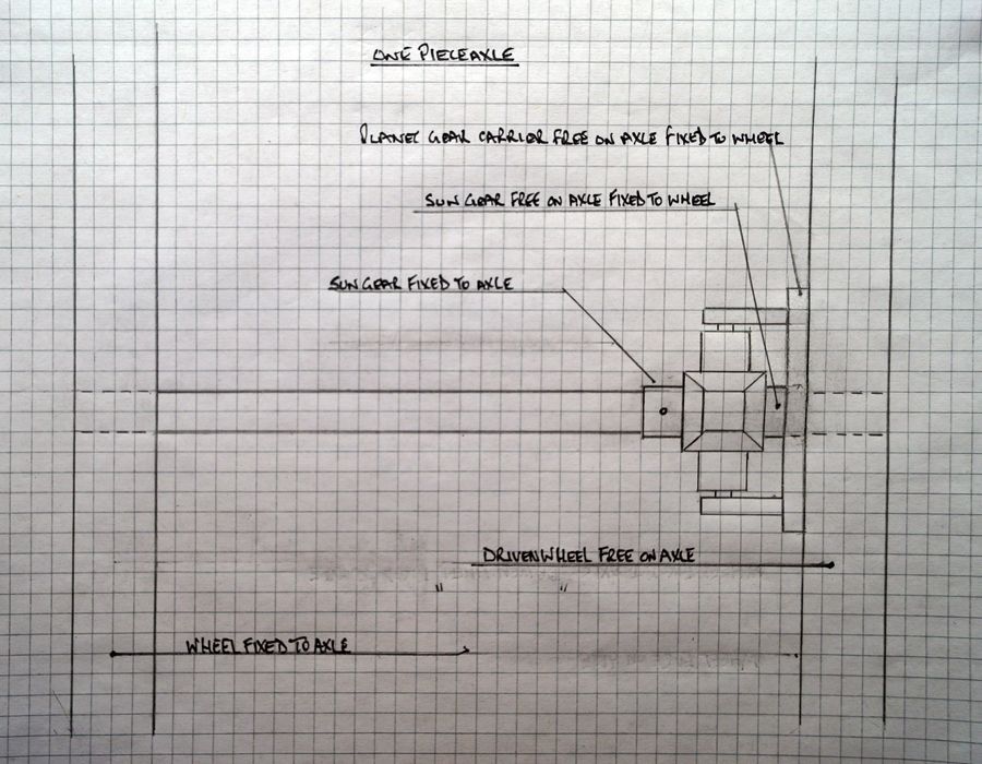
That is basically the arrangement but! Where is the drive coming in? If you are going to drive onto the axle then I think at first glance that will work – as long as the wheel with its "sun" gear and "planet" housing is free to rotate on the axle.
However, your terminology is a bit mixed up there. What you have drawn with 4 bevel gears is not a sun and planet diff. A sun and planet set up would be a bit different to that using straight cut rather than bevel gears. So 'correct' terminology for the above would be crown wheels for those mounted on the axle / wheel and pinions for those mounted in the diff.
Also on a 'normal' (if there is such a thing) traction engine the pinion carrier / diff housing / or as you have termed it 'planet gear carrier' would be the driven component, the final drive gear being mounted on its outer diameter and it would be free to rotate independently of axle, wheel or anything else. The inner crown wheel would be pinned to the axle as you have it, the outer crown wheel fixed to the wheel, as you have it. Thus the diff housing would be driven from the second or third shaft and drive on the crown wheels via the pinions. The wheel being loose on the axle, the opposite wheel being fixed to the axle so the 'differential' movement imparted by going round the corner will be taken up between the two crown wheels.
Not sure I have explained that in a very clear fashion! Maybe Jason can do one of his CAD drawings which would show it better.
Paul.
Ron Laden.


