Electric Traction Engine

Advert

Electric Traction Engine

Home Forums Miscellaneous models Electric Traction Engine

Viewing 25 posts - 226 through 250 (of 277 total)
  • Author
    Posts
  • #430362
    Ron Laden
    Participant
      @ronladen17547

      Probably an obvious question but I had better check, to date I have only cut metric threads on the lathe but for the engine I am looking at some BA sizes. The inch table on the lathe for the change wheels/gearbox settings gives TPI which are close and I assume using those gives no fit issues..? i.e 2BA – 31.4 tpi – lathe 32. 4BA – 38.5 tpi – lathe 38.

      Advert
      #430372
      SillyOldDuffer
      Moderator
        @sillyoldduffer
        Posted by Ron Laden on 25/09/2019 08:01:22:

        Probably an obvious question but I had better check, to date I have only cut metric threads on the lathe but for the engine I am looking at some BA sizes. The inch table on the lathe for the change wheels/gearbox settings gives TPI which are close and I assume using those gives no fit issues..? i.e 2BA – 31.4 tpi – lathe 32. 4BA – 38.5 tpi – lathe 38.

        My reaction:

        1. Replace BA with metric sizes unless there's a strong reason not to.
        2. It's faster, easier and more accurate to make small threads with taps and dies rather than a lathe. (Tracy Tools are your friend!)
        3. Yes you can approximate a BA pitch to the nearest metric or tpi the lathe can do, but how successful it is depends on the length of thread. For example, substituting 32tpi for 2BA the thread match will be out by 0.6 of a turn over a length of 1", which is too much. In practice a tightly dimensioned thread will jam much earlier, making the 32tpu bodge only good for a few turns of engagement. A slightly wrong pitch will also misplace the bearing surfaces and reduce the strength of the joint. Reducing the diameter of the tpi bolt would allow more turns to engage but the joint strength will be reduced even more. If strength matters approach pitch errors with caution.

        I've assumed the tpi male is entering an existing BA female. If male and female are both cut by you at the same tpi, they will match correctly, but they aren't standard BA or Imperial threads. Again, that may not matter.

        Depending on the change wheels available it may be possible to set up the banjo to get a close match. As I'm poo at sums I'll leave the maths needed to calculate the gear combinations needed to produce a wanted pitch to someone else!

        Dave

        #430377
        Ron Laden
        Participant
          @ronladen17547

          Thanks Dave, actually I have just read in a couple of places that in general people stay clear of BA on the lathe. I have some taps and can get some dies plus studding etc. I didnt have any particular parts in mind but having just got some smaller head BA nuts and set screws I really like the look of them and would like to stay with BA for that reason. To be honest I didnt think the small difference in the tpi from the lathe settings would be a problem but I was obviously wrong. Anyway there will be a way around what ever comes up I,m sure.

          #430400
          Harry Wilkes
          Participant
            @harrywilkes58467

            Ron this post from yesterday maybe of help link

            H

            #430464
            Ron Laden
            Participant
              @ronladen17547

              Thanks Harry, the last link in that thread Nuts and Bolts for Model Engineers do a good range of BA, metric and UNC. They also have a very good range of one size smaller BA plus their pricing looks good.

              Ron

              #430497
              Ron Laden
              Participant
                @ronladen17547

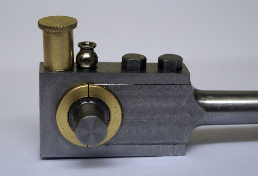
                Made up and fitted the big end oiler this morning, no its not to the Minnie drawing but some parts wont be though the majority will. I found the body in my odds and sods box and it just looked like a potential oiler and about the right size, all I had to do was turn the base under the ball to create a spigot for fitting. Then I turned up a brass cap, its a couple of mm taller than I would have liked but cant do much about that, there is a M4 threaded rod inside the cap which screws into the body and needed the length of cap to thread for the rod. I dont have a knurling tool but managed a light knurl by running the cap along under the edge of a file.

                dsc07134.jpg

                Edited By Ron Laden on 26/09/2019 09:25:14

                #430534
                Ron Laden
                Participant
                  @ronladen17547

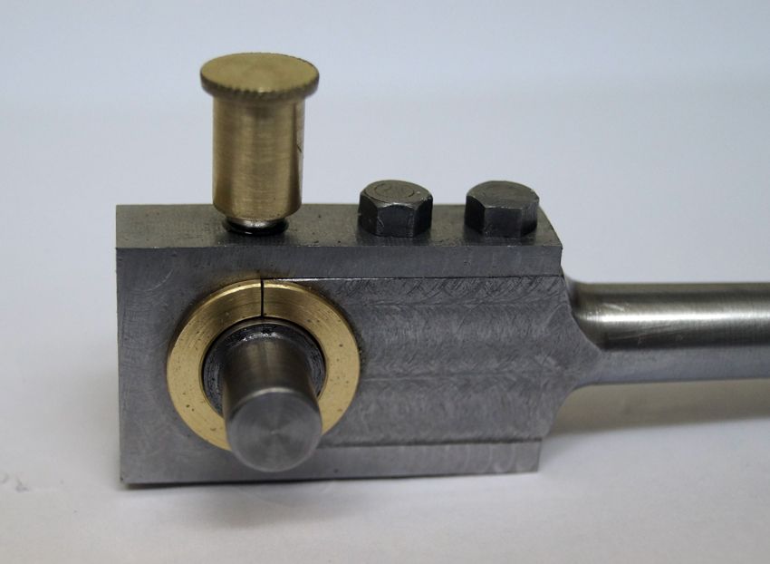
                  No not happy with it, its too tall and the more I look at it, it looks odd. Oh well a re make job.

                  dsc07136.jpg

                  #430538
                  Harry Wilkes
                  Participant
                    @harrywilkes58467

                    Ron the beauty of making things is if you don't like them you can change or re-make them thumbs up

                    H

                    #430539
                    Ron Laden
                    Participant
                      @ronladen17547
                      Posted by Harry Wilkes on 26/09/2019 13:44:27:

                      Ron the beauty of making things is if you don't like them you can change or re-make them thumbs up

                      H

                      Very true Harry, thats a bonus I guess.

                      #430544
                      Ron Laden
                      Participant
                        @ronladen17547

                        Just wondered are mush head rivets available in model eng sizes, I saw some truss head (I think thats what they were called) but they were very shallow, more so than a mush head.

                        Edited By Ron Laden on 26/09/2019 13:59:14

                        #430665
                        Ron Laden
                        Participant
                          @ronladen17547

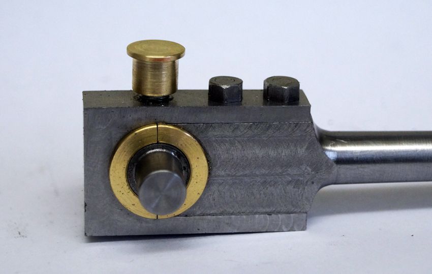
                          A shorter version oiler which I,m happy with.

                          dsc07144.jpg

                          #430889
                          Ron Laden
                          Participant
                            @ronladen17547

                            I assembled the crank using 638, I am going to pin the webs but waiting for pins to arrive. I was keen to see if it had turned out true, I havnt clocked it but it looks pretty good by eye so happy with that.

                            A bit of exciting video wink below of it running in the lathe.

                            #431001
                            Ron Laden
                            Participant
                              @ronladen17547

                              I wrongly assumed that the layout of the main parts/build of traction engines would be the same or similar across the various manufactures/designs. However looking at some pictures of a scale model Burrell I see it has no second shaft and the high/low gears and shift are fitted directly to the end of the crank.

                              I dont know what type of full size engine the Minnie is based upon but I wonder why they went down that path. Fitting gears to the end of the crank is simpler, cheaper, more compact etc, maybe just a different approach unless there other benefits of a second shaft.

                              #431020
                              Paul Kemp
                              Participant
                                @paulkemp46892

                                Ron,

                                Most full size engines fall into either the three shaft or four shaft configuration. The number of "shafts" in this description includes the crank and the rear axle. Probably the majority are 2 speed but some are 3 speed and fewer 4 speed. I think I can generalise and say pretty well all 3 shaft engines were 2 speed and four shaft 3 speed or more. All sorts of reasons for a fourth shaft and some advantages such as the ability to incorporate the diff on the third shaft rather than the axle which allowed the unit to be smaller. Also there were considerations with springing, ie if the axle moves on springs then the mesh of the gears will change. Various manufacturers had different ways of accommodating this. Avelling rollers used the four shaft method with low speed as a sliding gear on the outside and "high speed" as a sliding gear on the inside (between the horns in the crank pit) this allowed a greater reduction between crank and axle using smaller gears up to keep the road speed low suitable for rolling. Typically slow was dead slow and high was a bit faster than slow! When working low speed would be used and when travelling between jobs high speed (except for hills – rollers with smooth rolls especially didn't have a good grip on the road and many came to grief). So if you look at full size rollers with original gears slow is almost always very worn and high in pretty good nick! 4 speed engines were usually road haulage engines to give greater flexibility of speeds while pulling heavy loads. Most agricultural engines were 2 speed but as they got larger with exception of ploughing engines tending towards general purpose engines some were 3 speed.

                                Paul.

                                #431022
                                Ron Laden
                                Participant
                                  @ronladen17547

                                  Thanks Paul, quite a bit more to it than I imagined, I think it probably a good idea if I got a couple of books on TE,s and had a good read.

                                  You mention differential, I know I dont need one but I like the idea of having one, Jason posted a good compact design for one a while back.

                                  Ron

                                  #431342
                                  Ron Laden
                                  Participant
                                    @ronladen17547

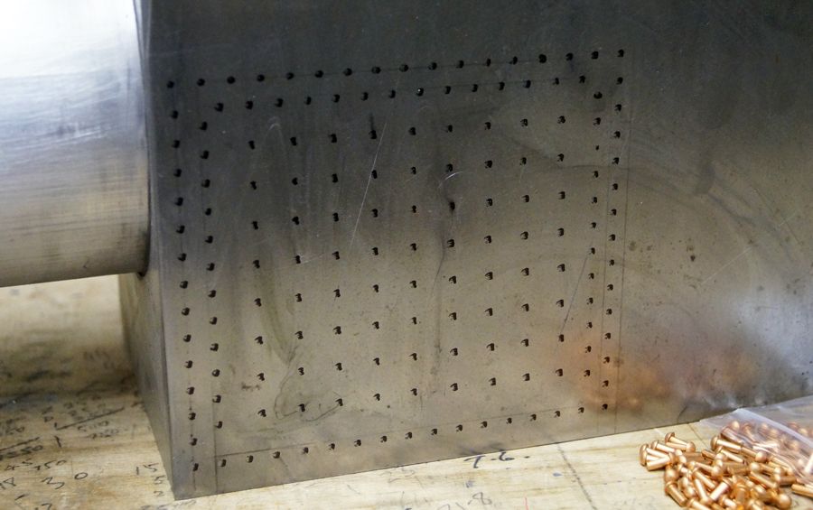
                                    With a pen and rule I roughed out a layout for the rivets in the hornplate to get a feeling for how they would look. Just based it on a mix of full size and model engines but I think it will look ok. Going to csk the holes on the inner face of the plate and dress back flush. For the stay rivets I,m still trying to find some shallow head type if they exist.

                                    dsc07158.jpg

                                    Edited By Ron Laden on 01/10/2019 13:30:03

                                    #431363
                                    JasonB
                                    Moderator
                                      @jasonb

                                      You only need a very shallow CSK infact just deburring the holes will do. Then cut the rivits so they will be just about flush with the inner face and all you need do is ctr punch them which will expand them enough to hold. Dab of Loctite won't do any harm.

                                      If you start trying to pein then over to fill a CSK then you will end up with a distorted plate.

                                      You could reduce the number of stays by at least 1/3rd and then it is not such a job to reduce the rivirt heads in teh lathe to make them look like stays

                                      #431370
                                      Ron Laden
                                      Participant
                                        @ronladen17547
                                        Posted by JasonB on 01/10/2019 16:17:20:

                                        You only need a very shallow CSK infact just deburring the holes will do. Then cut the rivits so they will be just about flush with the inner face and all you need do is ctr punch them which will expand them enough to hold. Dab of Loctite won't do any harm.

                                        If you start trying to pein then over to fill a CSK then you will end up with a distorted plate.

                                        You could reduce the number of stays by at least 1/3rd and then it is not such a job to reduce the rivirt heads in teh lathe to make them look like stays

                                        Thanks Jason, great advice as always.

                                        I was only going to go with a shallow csk but never thought about distorting the plate which I can see now. The ctr punch method sounds quick and easy so thats good. Also reducing the number of stay rivets is good news as I did wonder if I had too many and seeing your picture above I can probably reduce by half.

                                        Thanks again.

                                        #431476
                                        Ron Laden
                                        Participant
                                          @ronladen17547

                                          Just ordered a 3.5 inch square piece of ali for the cylinder block, I am going to try and machine it in one on the mill using the rotary table. I think it can be done or at least I hope so, I have worked out a plan of attack but we will see.

                                          Also I have been searching the Minnie drawings for the pin which connects the crosshead to the conrod but of course there isnt a drawing. The pin is described in the build though as a piece of hardened silver steel which runs in the conrod with no bearing. I am going to turn up a thin walled bronze bearing as Jason suggested to me and fit that to the conrod. I have also been thinking about the crosshead guide which on the Minnie are the pair of parallel bars but I do like the idea of the cylindrical guide I have seen on other engines. The ones I have seen have been from castings but I wouldnt imagine too difficult to produce from round bar, dont know yet, undecided.

                                          #431564
                                          Ron Laden
                                          Participant
                                            @ronladen17547

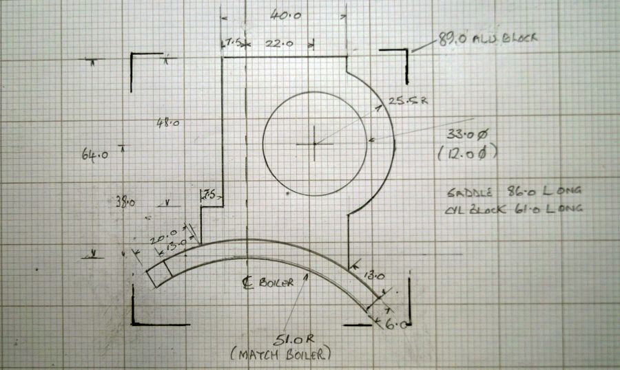
                                            Another of my basic working sketches showing the cylinder at actual size, I have indicated the 3.5" block it will come from.

                                            I have drawn the bore at the size it would be with a piston and liner but of course there is no piston so it will come down to 12mm dia. I am going to extend the cylinder cover into the bore to offer a bit more support for the piston rod, probably by about 5 mm that will make the cover 20mm deep overall, the piston rod is 6.5mm dia.

                                            Thats the plan anyway.

                                            dsc07162.jpg

                                            #431788
                                            Ron Laden
                                            Participant
                                              @ronladen17547

                                              I came across a picture of a Wallis and Steevens roller, what an odd looking engine with the boiler slanting steeply down towards the rear. At first glance it looks as if the boiler is broken into two and collapsed, certainly different though from a modelling point of view, I cant imagine there are too many of those around.

                                              #431931
                                              Ron Laden
                                              Participant
                                                @ronladen17547

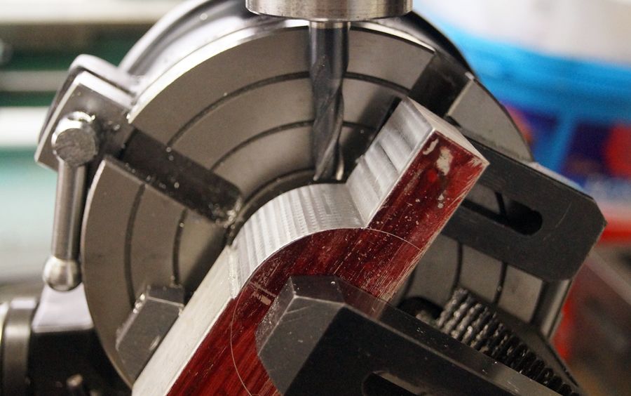
                                                Should have the alu block for the cylinder Monday and not having milled an outside radius before thought a bit of practice could be useful. The length of the cylinder block will be 60mm but I only had a piece of 30mm but ok for practice. I was thinking of cutting the rad with the side of an end mill but at 60mm and even with a long series cutter I would still need to turn it over and cut it from both ends.

                                                I then remembered from one of Jasons build threads him cutting a radius with a series of facets and finishing by hand, that seemed a good idea so gave it a try. I worked around the rad in 3 degree increments and must admit it wont need too much work with the file for a good finish (thanks Jason). I did machine away the bulk in advance so it wasnt too many cuts for the rad, really enjoyed doing it.

                                                dsc07165.jpg

                                                Edited By Ron Laden on 05/10/2019 16:55:04

                                                #432018
                                                Ron Laden
                                                Participant
                                                  @ronladen17547

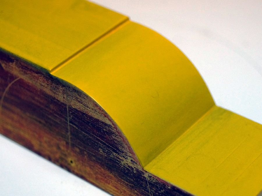
                                                  Finished the test rad with a medium and fine file followed with an emery wrapped file. I thought a couple of light coats of paint would show up the finish and shape, quite pleased with it, if I can copy that on the cylinder I will be happy. .

                                                  dsc07181.jpg

                                                  #432033
                                                  JasonB
                                                  Moderator
                                                    @jasonb

                                                    Looks good Ron.

                                                    #432039
                                                    Ron Laden
                                                    Participant
                                                      @ronladen17547

                                                      Thanks Jason, as I mentioned it was seeing the method of cutting facets around the rad which was in one of your threads that got me there. In another set up I did, I,ve got my boring head adjusted for the boiler rad in the bottom of the cylinder, did a test piece and its a nice close fit.

                                                    Viewing 25 posts - 226 through 250 (of 277 total)
                                                    • Please log in to reply to this topic. Registering is free and easy using the links on the menu at the top of this page.

                                                    Advert

                                                    Latest Replies

                                                    Home Forums Miscellaneous models Topics

                                                    Viewing 25 topics - 1 through 25 (of 25 total)
                                                    Viewing 25 topics - 1 through 25 (of 25 total)

                                                    View full reply list.

                                                    Advert

                                                    Newsletter Sign-up