Effect of Tensioning a Boring Bar

Advert

Effect of Tensioning a Boring Bar

Home Forums Work In Progress and completed items Effect of Tensioning a Boring Bar

Viewing 25 posts - 126 through 150 (of 163 total)
  • Author
    Posts
  • #451778
    Michael Gilligan
    Participant
      @michaelgilligan61133

      That’s real progress, Dave yes

      If you can get the elephants back on the job … May I suggest that [to model the contentious aspect of this] you need to apply a compressive end-load to the pin, rather than just tying both ends to the tube.

      My ‘arm-waving’ analysis of it is that loading the pin in compression [which is what we do by using it as a clamp] stretches the tube, and it’s that preload by extension which increases the overall stiffness.

      Keep up the good work, and keep the elephants fed & watered.

      MichaelG.

      Advert
      #451781
      Grindstone Cowboy
      Participant
        @grindstonecowboy

        Been following this thread with interest, and have possibly understood about 5% of the hard sums, but a thought occurred to me – it's all been about trying to stretch the the outer tube with an inner push-rod, yes?

        How about the other way around? Using a threaded inner, fixed at one end and with a nut and washer on the other, thus compressing the outer?

        No idea whether it would be better or worse, just musing.

        #451786
        duncan webster 1
        Participant
          @duncanwebster1

          Dr Dave seems to be on the case, but if need be I have another FE man who is prepared to have a look. Would need more dimensions, outside diameter, hole diameter, rod diameter, length to name but a few. The clearance twixt rod and hole probably matters quite a lot, if it's a very good fit it will be forced to follow the shape of the outer, if not, not if you see what I mean

          Edited By duncan webster on 11/02/2020 22:30:29

          #451815
          Martin Kyte
          Participant
            @martinkyte99762
            Posted by DrDave on 11/02/2020 19:45:59:

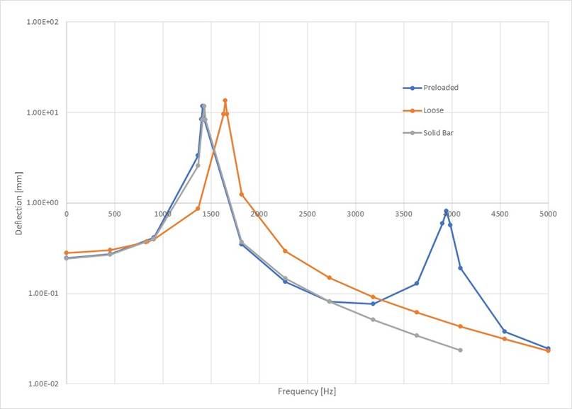
            This purports to be a 10 mm tube with a 6 mm hole with a 5.8 mm pin down the centre, both 70 mm long. Material is "steel". A nominal 200 N shear load is applied at the RH end and the LH end is built in. I also found a solid 10 mm bar lurking in another corner.

            Varying the frequency of the 200 N load from 0 Hz to 5 kHz gave the three curves below. They are not all quite what I expected…

            The solid bar gave the silver curve: a typical single degree of freedom forced response curve. Good. The "Loose" curve is for the model shown above: only the outer tube has responded to the load. The static deflection is slightly greater, because it is hollow. To my surprise, the natural frequency and the size of the peak have increased (not that the axis has a log scale). The frequency has gone up because the mass has decreased more than the tube's moment of inertia, one of the useful properties of a tube. I am not sure why the magnitude of the peak has gone up.

            I then tied the two free ends together. I have called this "preloaded", to signify that it is modelling a boring bar when it has been pre-loaded. This has produced some interesting results. It has two resonance peaks: one for the tube and one for the bar. I am surprised that the first peak, and its magnitude, are nearly identical to those for the solid bar. Make from that what you will, because I certainly don't know!

            Evidently the two-piece boring bar does work to reduce/eliminate chatter, but the mechanism but which it does this is still obscure. I would suggest friction between the two parts acting to damp the vibration, but the elephants had all left the office by then & were nowhere to be found…

            fem response.jpg

            Dave

            Very interesting. Effectively the rod down the middle of the bar has added another degree of freedom allowing resonant motion at two different frequencies.

            So maybe the best way of thinking about the tensioned bar is as two coupled oscillators something along the line of 2 pendulums of dissimilar length both hanging on a line which couples them togather. Energy will be transferred back and forth from the one to the other at at the beat frequency in a similar way to the employment of tuned mass dampers for tall buildings etc (google it).

            This company actually produces a tuned mass damper boring bar.

            **LINK**

            I don't think for a minute that the simple tensioned bar we have been discussing approaches a tuned system however the addition of the tensioned rod certainly seems to have the effect of disrupting the single frequency simple oscillation.

            I did try and find a video of coupled pendulums of different lengths but so far have failed.

            regards Martin

            #451843
            Michael Gilligan
            Participant
              @michaelgilligan61133
              Posted by duncan webster on 11/02/2020 22:28:14:

              Dr Dave seems to be on the case, but if need be I have another FE man who is prepared to have a look. Would need more dimensions, outside diameter, hole diameter, rod diameter, length to name but a few. The clearance twixt rod and hole probably matters quite a lot, if it's a very good fit it will be forced to follow the shape of the outer, if not, not if you see what I mean

              .

              A suggestion, if I may [and if it doesn’t involve Dr Dave’s Elephants in too much re-work]

              12.0mm o/d, 6.2mm i/d, blind at one end, and tapped M8 at t'other

              6.0mm push-rod, and an M8 screw to apply pressure

              at least 200mm long … so that we keep the resonant frequencies down a bit

              preferably ‘grounded’ at the screwed end, for realism

              … but O.K. to model it free-free if that’s more convenient.

              MichaelG.

              #451864
              Graham Meek
              Participant
                @grahammeek88282

                I have been looking at the clamping end of the push-rod in my boring bars. While the 45 degree flat should exhibit a straight line wear pattern of contact with the round tool bit, it does not. Instead there is a wear pattern resembling a very shallow "X".

                The push-rod is obviously twisting as the Allen grubscrew is tightened. This then leads on to another condition that the push-rod is experiencing. Not only is it being compressed, but there is also a twisting moment being induced. Obviously the turning effort on the end of the grubscrew is being transferred to the push-rod. Due to the wedge action at the clamping face, the twist on the push-rod can only go so far. Once the wedge action has taken place. How much more of the torque applied to the grubscrew is being absorbed by twisting the push-rod beyond this point. I had better just add that the grubscrews I use are all Half Dog points so present a flat face to the end of the push-rod.

                The induced twist is also of an opposite sense to the force applied by the cutting tool. Tightening the grubscrew induces a clockwise moment on the push-rod looking on the back end of the boring bar. While the cutting tool puts a counter clockwise moment on the boring bar. Thus the push-rod has now become a pre-loaded Torsion bar, similar to some suspension systems used in the past.

                Unlike the suspension system where the torsion bar is only dealing with the up and down movement of the suspension arm and has no compression or tension end loading. The torsion bar in the push-rod system is under compression, as well as being constrained at either end.

                Unfortunately the days are long gone since as an apprentice I used to push numbers around on paper working out the stresses in under carriage legs at Dowty Rotol ltd. These were the days of the slide rule, and the Olivetti computer took half a day to programme. This is a system beyond my capabilities and needs some younger grey cells.

                As I said in my previous post, I was sure there was a lot more going on when the boring bar is under tension using a push-rod. Obviously Arnold and George knew this too, I do not think they just stumbled across this.

                I have another test in the pipe line to measure this twist, but it will have to wait for some warmer weather. "There is snow on them thar hills", (just across the border in Wales), and the workshop has temporarily become a no-go area.

                Regards

                Gray,

                Edited By Graham Meek on 12/02/2020 16:37:24

                #451898
                DrDave
                Participant
                  @drdave

                  Regarding the magnitude of the pretension (or compression) on the assembly, this will have no effect on the simple, linear model that I showed above. The FE program does not even have the ability to consider preloading. Why no effect? The response is really just the sum of the vibration modes of the system: I will have to dig into a little maths, so bear with me. The natural frequency of a system boils down to frequency = sqrt(stiffness/mass). In this case, the stiffness is effectively Young’s modulus, which is independent of load (if you don’t yield it). So preload cannot affect the fine element analysis.

                  But, in practice, there are all sorts of non-linear effects creeping in. Friction between the parts possibly being one. I see no point in following the analysis route any further, so I will bow out (and let the elephants loose again). I think physical testing is the best way forward, but I do not have access to the actuators and accelerometers requited to do this justice.

                  Lastly, Gray’s comments and findings about torsion are interesting. However, after chatter has started, any torsional frequencies will be so high that I suspect that they play no part in the process. However, I have been wrong with some of my preconceptions on this topic and I am quite happy to be proven wrong on this, too!

                  Dave

                  #451916
                  Michael Gilligan
                  Participant
                    @michaelgilligan61133
                    Posted by DrDave on 12/02/2020 19:31:54:

                    Regarding the magnitude of the pretension (or compression) on the assembly, this will have no effect on the simple, linear model that I showed above. The FE program does not even have the ability to consider preloading. Why no effect? The response is really just the sum of the vibration modes of the system: I will have to dig into a little maths, so bear with me. The natural frequency of a system boils down to frequency = sqrt(stiffness/mass). In this case, the stiffness is effectively Young’s modulus, which is independent of load (if you don’t yield it). So preload cannot affect the fine element analysis.

                    But, in practice, there are all sorts of non-linear effects creeping in. Friction between the parts possibly being one. I see no point in following the analysis route any further, so I will bow out (and let the elephants loose again). I think physical testing is the best way forward, but I do not have access to the actuators and accelerometers requited to do this justice.

                    .

                    Thanks, Dave … I remain convinced that preload is the essence of this, but if the FE can’t accommodate it then I agree that we would be wasting your elephant herd’s time.

                    Physical testing would be informative, but I don’t have access to the shakers and instrumentation either.

                    sad MichaelG.

                    #451926
                    duncan webster 1
                    Participant
                      @duncanwebster1

                      Rather than Michael's figures it makes sense to use Graham's real figures in an FE model, then we can compare Graham's measurements with FE predictions and see where we go from there. If Graham is reading this perhaps he would supply the dimensions

                      #451945
                      Michael Gilligan
                      Participant
                        @michaelgilligan61133
                        Posted by duncan webster on 12/02/2020 21:51:00:

                        Rather than Michael's figures it makes sense to use Graham's real figures in an FE model, then we can compare Graham's measurements with FE predictions and see where we go from there. If Graham is reading this perhaps he would supply the dimensions

                        .

                        Fine, Duncan … Dr Dave has already withdrawn, so it looks like your team is doing the job.

                        The only reason I suggested a longer bar was that it would reduce the resonant frequency … which means larger displacements for a given g, which means that a coarser mesh might provide proportionately better resolution.

                        It’s 30+ years since I’ve done any of this … so I may well be worrying unnecessarily.

                        Whatever you choose to do … I will be delighted to see some results.

                        MichaelG.

                        .

                        I’m out of my depth here … but this may be of interest :

                        https://www.researchgate.net/profile/Paulina_Krolo/publication/304007778_The_Guidelines_for_Modelling_the_Preloading_Bolts_in_the_Structural_Connection_Using_Finite_Element_Methods/links/5770d4a808ae6219474882d6/The-Guidelines-for-Modelling-the-Preloading-Bolts-in-the-Structural-Connection-Using-Finite-Element-Methods.pdf?origin=publication_detail

                        Edited By Michael Gilligan on 12/02/2020 23:09:33

                        #451988
                        Michael Gilligan
                        Participant
                          @michaelgilligan61133

                          Posted by Michael Gilligan on 12/02/2020 23:01:50:

                          .

                          The only reason I suggested a longer bar was that it would reduce the resonant frequency … which means larger displacements for a given g, which means that a coarser mesh might provide proportionately better resolution.

                          .

                          .

                          Sorry folks … that was rather clumsily worded, and is probably ambiguous

                          What I mean is that any given size of elements will provide proportionately better resolution on a long bar than on a short one.

                          Alternatively, we could express it as — a coarse mesh might suffice for analysis of large displacements.

                          [But obviously, in any situation, a finer mesh gives better resolution]

                          MichaelG.

                          Edited By Michael Gilligan on 13/02/2020 08:51:26

                          #452006
                          Graham Meek
                          Participant
                            @grahammeek88282

                            The overall length of the boring bar was 90 mm, 30 mm was gripped in the toolpost, in a sleeve. The push-rod was 3 mm diameter and the hole through the bar 3.2 mm. The 1/8" cutter was on the extreme corner of the bar which itself was 10 mm diameter. The push-rod is locked by an M4 Allen grubscrew.

                            This bar also had two flats running the full length of the bar and parallel to the cutter centre-line, (see initial post). The dimension across the flats was 9 mm. These flats are used to hold and orientate the boring bar in the Boring head. This boring bar has despite an L/D of 7 when in the boring head produced: dare I say, perfect holes, in a brass fabrication to take a radial bearing.

                            The bending loads and the torsion loads were all applied 5 mm in from the cutter end of the boring bar using a screw tensioning device and an elderly spring balance. As all the readings were taken from the same balance then it should make no odds about its age. Ideally I would have preferred a force gauge but it was a case of horses for courses.

                            Regards

                            Gray,

                            #452056
                            Graham Meek
                            Participant
                              @grahammeek88282

                              boring bars-twist test rig.jpg

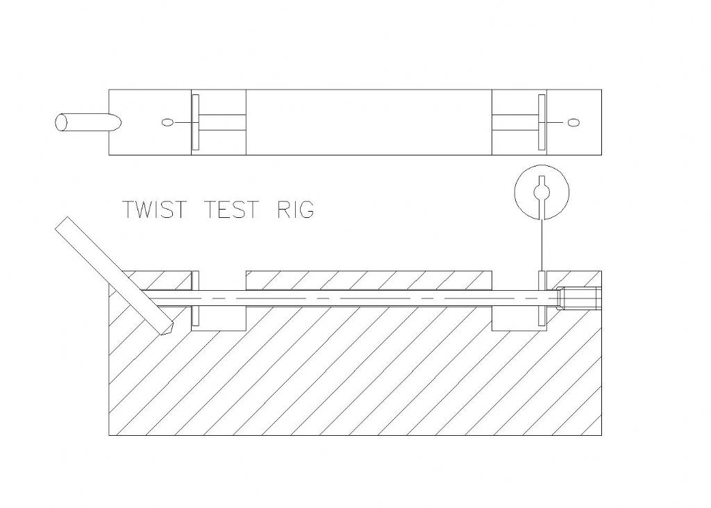
                              This afternoon I had a chance to make the Twist test rig I wanted to. The above drawing gives the set-up and the push-rod is the one from the Test Boring bar. The BMS block is 90 mm long by 12 mm wide and the two "C" shaped discs are 10 mm diameter and a friction fit on the push-rod. The discs have a Zero mark to coincide with one on the main block. The discs are not allowed to contact the faces thus eliminating any drag that might give a false reading.

                              The discs are aligned with the Zero mark once all the slop has been taken out of the system, but the tool bit can just about be turned by hand. A x40 pocket microscope with a graduated graticule is used to align the Zero's. The M4 grubscrew is then tightened, which is about a third of a turn.

                              While the disc at the tool bit end did move it was barely the width of the Zero line. This is what I would expect. The movement at the other end was more pronounced and equates to 3.436 degrees. This is approximately 3% of the tightening angle.

                              The gap left between the disc and the test rig opened up about 0.25 mm which is in keeping with the screw thread displacement.

                              Thus my supposition made earlier about the bar being in compression and in torsion is proven with this rig. No doubt with access to more sophisticated equipment like strain gauges it would be possible to quantify what is going on, but I am satisfied with my tests that there is a benefit to be had from this arrangement.

                              Regards

                              Gray,

                              #452102
                              duncan webster 1
                              Participant
                                @duncanwebster1
                                Posted by Graham Meek on 13/02/2020 10:50:21:

                                The overall length of the boring bar was 90 mm, 30 mm was gripped in the toolpost, in a sleeve. The push-rod was 3 mm diameter and the hole through the bar 3.2 mm. The 1/8" cutter was on the extreme corner of the bar which itself was 10 mm diameter. The push-rod is locked by an M4 Allen grubscrew.

                                This bar also had two flats running the full length of the bar and parallel to the cutter centre-line, (see initial post). The dimension across the flats was 9 mm. These flats are used to hold and orientate the boring bar in the Boring head. This boring bar has despite an L/D of 7 when in the boring head produced: dare I say, perfect holes, in a brass fabrication to take a radial bearing.

                                The bending loads and the torsion loads were all applied 5 mm in from the cutter end of the boring bar using a screw tensioning device and an elderly spring balance. As all the readings were taken from the same balance then it should make no odds about its age. Ideally I would have preferred a force gauge but it was a case of horses for courses.

                                Regards

                                Gray,

                                I'll produce a CAD model and send it to Gray to make sure I've got it right and then send it to my FE man. Don't expect immediate results, he's doing it out of interest, not because he's a model engineer.

                                #452173
                                duncan webster 1
                                Participant
                                  @duncanwebster1

                                  Gray, have sent email with drawing

                                  #452229
                                  Graham Meek
                                  Participant
                                    @grahammeek88282

                                    Hi Duncan,

                                    Unfortunately your email was in my Spam tray with a Google warning.

                                    Anyway I have managed to safely extract and open the dxf file. Which my version of AutoCAD did not like, it said there was an error and refused to open it. Finally using Autodesk DWG TrueView 2020 I was able to view the drawing.

                                    A couple of things wrong with the drawing, but only minor.

                                    The 3.2 diameter hole does not go all the way through, it stops 10 mm from the tool bit. The hole is then 3.05 mm from there to the tool bit, and it stops at the tool bit. It does not go all the way through the boring bar as drawn. Also the tool bit is 1/8" diameter not 3 mm.

                                    Regards

                                    Gray,

                                    #452240
                                    duncan webster 1
                                    Participant
                                      @duncanwebster1

                                      OK I've changed it and sent it off to the FE man. as I said, don't hold your breath

                                      #452846
                                      Graham Meek
                                      Participant
                                        @grahammeek88282

                                        I managed to quantify the torque applied to the grubscrew on my boring bar yesterday. My 120 degree turn, produced by years of practice, produces a torque of 889 N mm. Unbrako recommend a torque of 1863 N mm on an M4 grubscrew, while HoloKrome recommend 2270 N mm. Unbrako even state this torque can be applied with a standard Allen Key.

                                        While my torque is just under a 1000 N mm less than the lowest recommended value, this does still equate to a loading of 1111 N on the push rod, in old money 250 lb(f).

                                        Regards

                                        Gray,


                                        Edited By Graham Meek on 18/02/2020 12:25:09

                                        #453484
                                        Kiwi Bloke
                                        Participant
                                          @kiwibloke62605

                                          …er, apologies for coming to the party a bit late. Interesting discussion, but is it blurred by terminological inexactitude? Have we decided whether doing something to the bar affects its stiffness (as in Young's modulus) when strained or only its resistance to initial deflection (as in pre-load)? I can't see how stiffness can be altered without material being changed to something stiffer.

                                          #453558
                                          Graham Meek
                                          Participant
                                            @grahammeek88282

                                            In years gone by when I was learning my trade, mechanical engineering college courses included lab experiments.

                                            These followed a set and logical pattern, Object, Method, Results and Conclusion.

                                            The Object as I take it is the title of the thread, ie "Effect of Tensioning a Boring Bar"

                                            My Method was to compare a Plain (solid) boring bar with a Pre-tensioned one. During actual machining and, using the same test equipment, the same overhang and the same diameter boring bars, two tests were devised to check each bar in Bending and Torsion.

                                            The Results showed that during machining the Plain bar produced chatter, which was inaudible, while the pre-tensioned bar produced a bore with a very good finish.(Using the same spindle speed and Rate of Feed).

                                            It also showed that there was a slight increase in the effort required to Bend the pre-tensioned bar through a fixed distance. While there was a much more pronounced increase in the Torsional effort required to displace the pre-tensioned bar through the same set distance.

                                            The conclusions drawn from these tests are that the Pre-tensioned boring bar did benefit from being under tension, in that it produced better results. Both under machining conditions and under test. It was also concluded that the Push-rod was also experiencing a torsional loading which was of the opposite sense to the tool loading. (This was the subject of a second test, which proved this conclusion). It was also concluded that the Pre-tensioned boring bar was a complex system which needed greater knowledge to unpick the secret of why it produces better results, both dynamic and static.

                                            I do not think the question is about "stiffness", I think the question should be, as a structure, "Is the pre-tensioned boring bar more Rigid".

                                            There are two more test I have in mind, when time will allow, to show under working conditions what is happening.

                                            Regards

                                            Gray,

                                            #453576
                                            Michael Gilligan
                                            Participant
                                              @michaelgilligan61133
                                              Posted by Graham Meek on 22/02/2020 12:38:35:

                                              […]

                                              I do not think the question is about "stiffness", I think the question should be, as a structure, "Is the pre-tensioned boring bar more Rigid".

                                              […]

                                              .

                                              With the greatest respect, Gray …

                                              In ‘Mechanics’ Rigid is a term of convenience which means infinitely stiff, and there is no such concept as ‘more Rigid’

                                              i.e. it is a convenient assumption, made when the calculations would otherwise be too difficult.

                                              MichaelG.

                                              #453591
                                              Graham Meek
                                              Participant
                                                @grahammeek88282

                                                Michael,

                                                Point taken, and yes the calculations are beyond me. Despite my HNC in Mechanical Engineering (circa 1970).

                                                I did however think if I used the word "stiffer" someone would only quote Young's Modulus, again.

                                                The old wooden beams used to raise loads into upper storey's of buildings had one point of contact, the wall. The outer end thus has 4 degrees of freedom. Putting a brace or tie-rod between the free end of the beam and the wall directly above the beam, brings these degrees of freedom down to 2. Having two braces and splaying them apart where they attach to the wall above the beam reduces the degrees of freedom to 0. As Braces are added, the structure becomes "more Rigid", or "stiffer", plus the load carrying capacity goes up.

                                                Regards

                                                Gray,

                                                #453717
                                                Kiwi Bloke
                                                Participant
                                                  @kiwibloke62605

                                                  I didn't mean to offend Graham Meek by mentioning Young's modulus. Gray's experiments are far more useful in practice than pages of waffle and surmise and he deserves a vote of thanks from all who are interested in this subject.

                                                  I'm trying to understand what's going on. I of course accept the experimental evidence and can use this knowledge, to some extent, in future use of boring bars, but I'm the sort of awkward beggar who likes to know 'why', not just 'what'.

                                                  My belief is that the tensioned bar isn't much like the brace or guy-wire arrangement above (because it's a long thin structure), but that it is pre-loaded. This makes initial deflection (lateral and torsional) minimal, until the preload is overcome. My understanding is that preloading a sprung system moves the stress/strain curve sideways, but doesn't alter its slope. So, with appropriate preloading, stress, up to the preload, can be applied without producing strain. The stress/strain curve of the preloaded system is thus initially vertical i.e. infinite stiffness (where 'stiffness' means Young's modulus). Or perhaps not. Have I gone wrong somewhere?

                                                  #453723
                                                  Michael Gilligan
                                                  Participant
                                                    @michaelgilligan61133

                                                    Kiwi Bloke

                                                    I think your closing paragraph summarises the situation nicely.

                                                    As you will see from my earlier posts on this long thread; I have tried to draw comparison with pre-stressed concrete beams, pre-stressed steel beams, and vehicle springing … but this appears to have fallen upon deaf ears.

                                                    I eagerly await the FE Analysis

                                                    MichaelG.

                                                    #453755
                                                    Graham Meek
                                                    Participant
                                                      @grahammeek88282

                                                      Kiwi Bloke,

                                                      No offence was taken on my part by you mentioning Young's Modulus. I have you to thank for the Maximat Screwcutting Clutch design. You prompted me to take another look at the problem.

                                                      Young's Modulus is, as you rightly say, a Ratio of Stress over Strain. It's use in answers on this thread, sheds no more light on why the Plain solid boring is out performed by the pre-tensioned boring bar. If greater thought was applied to this problem we might be nearer an answer.

                                                      I too am struggling to understand what is going on, but I do like to see things through and by experimentation I have sorted in my own mind that the pre-tensioned bar is better. By my experimentation I have added values to a mostly theoretical thread.

                                                      Regards

                                                      Gray,

                                                      Michael,

                                                      I do not think your analogies were wrong, it sometimes pays to scale things up and look at the problem from a different perspective.

                                                      Like my example above with the wooden beam and the metal tie rods. The materials have not changed but the resultant structure is better. It is far removed from the boring bar problem, but the boring bar is just like the initial wooden beam attached at one end, that is to the tool post. Adding the push-rod changes the outcome, why it does escapes me.

                                                      As regards the FE analysis I hope you can draw conclusions from it, as it is all double dutch to me.

                                                      Regards

                                                      Gray,

                                                      Generally,

                                                      I received on Friday from a good friend an article by Martin Cleeve, Model Engineer 16th Sept 1966, pages 824-826. This, until Friday, was the first time I had read the article. I only started taking Model Engineer in Sept 1968, when I started my apprenticeship.

                                                      Martin's work is highly regarded by me, and many others. Thus it came as no surprise to me that his boring bar of choice was one using a push rod. His only drawback to using this type of bar was the need for the long drilled hole. He does however go on to describe a composite boring bar, part push-rod, part plain. That part I thought was a clever and an original bit of thinking. This latter bar does to a certain extent "put a stone in the ashes" on what I have been thinking. However he does say he could not see any difference between the bars in use.

                                                      The bars are threaded together, and in his "Practical Test" he states he had the joint "purposely left only finger tight", while plunging a 0.135" wide cutter into a 1" bore at 145 rpm.

                                                      Thus this is something that I would like to know the answer to "what is going on" with these bars. As this "structure" is even more complex.

                                                      Regards

                                                      Gray,


                                                      Edited By Graham Meek on 23/02/2020 12:45:57

                                                    Viewing 25 posts - 126 through 150 (of 163 total)
                                                    • Please log in to reply to this topic. Registering is free and easy using the links on the menu at the top of this page.

                                                    Advert

                                                    Latest Replies

                                                    Viewing 25 topics - 1 through 25 (of 25 total)
                                                    Viewing 25 topics - 1 through 25 (of 25 total)

                                                    View full reply list.

                                                    Advert

                                                    Newsletter Sign-up