Had a delivery today from 'The Engineers Emporium' in the form of castings for the 1/2 scale Economy hit and miss engine.
I did not realise until I phoned them to order that they do this engine in either aluminium castings or all cast iron. I went for the all cast iron set. Adrian at the EE explained to me that they were short of the CI casting for the hopper for a few weeks as they are waiting for a delivery from the foundry but could have that casting in aluminium if I wanted. I asked him to send what he had as it will be a while before I get to the hopper and to send the CI one on later to me. I should add that they do many fold the number of castings for engines and general items that they do not have upon their website.
Castings seem on inspection to be of very good quality with nice edges and corners, true to shape and casting halves very well positioned. Initial impressions are although I am yet to start to cut them is that they are of better quality than the ones I have had in Stuart kits – Bit of surface corrosion on them when they have been in storage but that is of no matter.
Bound booklet of drawings is very impressive with each part having it's own page along with exploded drawings. (probably 100 ish sides in total) The drawings are in metric. Personally I prefer to work in imperial. …….. But that's just me.
It's a bit of a lump as you can see and I may have to get a bit creative when machining some of the castings. The supplied raw castings so far weigh 36kg (delivery guy did not seem happy) which is about 80lbs. 13kg of this is the flywheels. Added to this needs to be the weight of the hopper, conrod and crank. Then minus a bit from machining swarf. So will probably weigh about the same as the similar sized Galloway engine (90lbs according to Galloways specs)
Sooooooooo. Besides spending time reading the drawings. Where the hell do I start.??
I like to get the crank made before I do things like bore the bearings and flywheels, that way if you have problems getting a finish on the cank and end up a bit off specified size you can bore the other parts to suit.
Also don't be in a rush to drill out the head mounting holes, they may be better tapped first so you can hold the head on standoffs to machine the bottom and valve guides/seats.
SAE 660, quite nice to machine and not as grabby and stringy as some of the more orange toned ones.
If the main bearings are single flanged then you could look at oilite bushes which will be quite a bit cheaper, a couple of the US engines I have done came supplied with these.
As advised by Jason I made the main shaft of the crankshaft and the big end first. The metal for the webs is on order.
Called at my mates to liberate him of some en8 for the shaft. But he has only got en16 or 24 so I used the 16. Had to have a little play with it to get it cutting to a reasonable finish. – The spec main dia is 20mm and reducing to 17mm. Also made them a bit longer to enable the fitting of a driving wheel on one side and engagement for a starting handle on the other.
Next onto one of the flywheels. Made a best guesstimate for centering.
Then cutting we did go.!
Little very short video.
Bored the hub so a nice snug fit onto the shaft. – I will need to take a trip to my mates to slot the hub for the keyways once both the flywheels are made.
Flipped it over and machined the other face.
Now I just have another flywheel to do this time with a 17mm hole in the hub. – I will make a madrel for final finishing and polishing them later when I have finished dropping and bashing them about during the rest of the build.
Steph upon seeing the parts arranged below asked. "Oh, you are making a cannon" ………… TBH I can see why she would think such.
Cannon, well it's not unknown for the open end of the cylinder to be called the muzzle, ans the other end the breech, I suppose the flywheels could be miss taken for wheels.
Nick, vinegar works surprisingly well for removing rust, albeit a little slow. Let it soak in 12% 24h then most of the surface rust will be gone, or else you could do electrolysis with a bath of machine wash detergent and a sacrificial piece of steel and a car battery charger (have fixed some old cast iron pots and pans this way).
Btw really nice machining, it is going to look great.
Decided to square up the base casting. So cleaned it up a bit and mounted it onto the mill with a fly cutter.
No nasty blow holes and the CI machined nicely again easily.
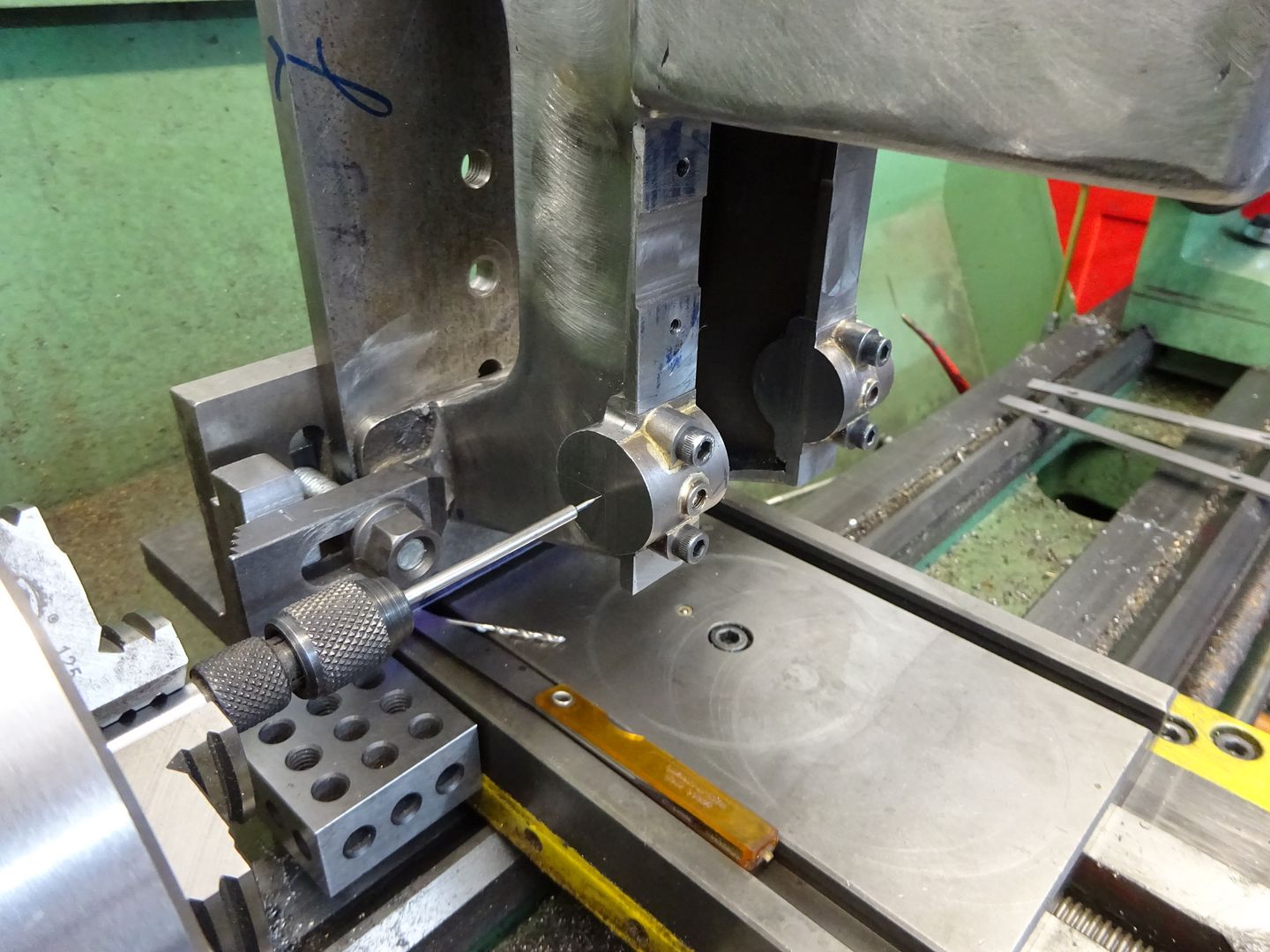
I thought I would as I said have to get 'creative' when mounting some of the castings in the mill. Doing the underside is the first one. I drilled 2 holes so that I could mount it securely, these will also be used when it comes time to bore the holes to take the main bearings. – I would have line bored them in the lathe but I don't have enough centre height from the top of the lathe saddle. One of the holes will be under the mounting plate of the cylinder / hopper casting so will not be visible and the other I will plug and fill after final machining and before painting. ……… Well that's the plan anyway.!
The paper under the bearing end is to create a 0.8mm shim. This was needed as the block under the other end is an imperial 2" one and the diff between that surface and the bearing beds is 50mm (bloody continentals and their damn metric system)
Made the crank webs by milling 2 pieces of steel loctited together to the right size.
Then 'spotted off' for the crank throw amount. I like to make webs as a pair if possible to ensure they are both a matched pair.
Over to the 4 jaw in the lathe and centered them up. – I know I could have done this in the mill with a boring head but TBH I am far more comfortable doing lathe work than milling work for some reason.
Next onto the main bearings. These are for some reason one piece and not the normal 2 piece ones that you would expect on an engine this size.??
Bored out to be a nice snug but slipping fit on the 20mm shaft.
And cut a 20mm groove into them.
By the time I have squared the bearing mounting blocks up on the inside of the bed casting there will be less than 20mm for them to sit into so I will have to devise a plan to build up about 1mm or so on the outside of the bearing pedistal blocks. – I could of course have made the recess a little narrower but I did not want to lose any bearing size.
I have read another build log that the builder also had discrepancies in the this area from what was specified on the drawing to what was possible with the casting. The castings for the Stuart No.4 I made were also shy of metal in a couple of areas.
Parted off
General arrangement with the 2nd one made and the webs separated and prettied up a bit. (shaft parts not yet finally joined)
I read quite a few times that model hit and miss engines can have a tendency to foul and oil their spark plugs up when run on petrol over gas. – Why is that anybody know.?
If you flood an engine with petrol the plug gets wet and takes a while to dry out, "flood" it with an excess of gas(propane etc) and you will just pump that out with one turn of teh crank and you will not be left with a build up of fuel across the spark plug gap.
Oiling the plug is not too much of an issue on horizontals or ones with te cylinder at the top its only ones like my Allman with the cylinder at the bottom which allows excess oil from the drip feed to drain down towards the plug
Some people also add a bit of oil or WD40 to their fuel mix which will make for an oilier engine, can't easily add oil to gas.
Think about using "colemans" fuel as it does not smell like petrol does
When I made my Economy it wasn't possible to machine the base casting to the drawings. For the crankshaft bearing supports I made the inner dimension to the drawings, but had to make the width of the bearing surfaces narrower. When I made the crankshaft bearings I made them full width as per the drawings. But I made the groove narrower, and biased, so that the inner and outer dimensions across the bearings coincided with the drawings.
Not a lot of progress in the last couple of days. But I have made the split bearing for the big end.
Soft soldered the splits together and centered the divide up in a 4 jaw. Bored out the center to 20mm and then cut the groove on the outside as can be seen.
This was a nerve wracking process as the wall thickness ends up at only 1.5mm on this. I had visions of the solder giving way or it collapsing like like clay on a potters wheel.
So towards the end I sharpened the tool and took light cuts of 0.1mm – Got there eventually and the solder joint held. I will split it later down the road with a blip of heat from a blow torch.
The steel has arrived for the conrod so it seems logical to make that next. – This may take some time.!