Economy Engine from Engineers Emporium

Advert

Economy Engine from Engineers Emporium

Home Forums Work In Progress and completed items Economy Engine from Engineers Emporium

Viewing 9 posts - 1 through 9 (of 9 total)
  • Author
    Posts
  • #458108
    Henry Brown
    Participant
      @henrybrown95529

      With the likelyhood of the country going into lock down due to Corona virus I have decided to have a go at building an Economy hit and miss engine from EE to help keep me sane. I have looked at builds for several engines, on here and from links from here, eventually It was a toss up between this and the Redwing, the final reason for choosing this is that it is slightly larger than the Redwing.

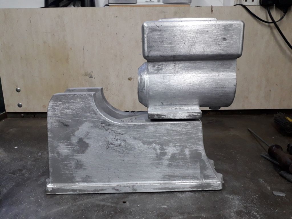
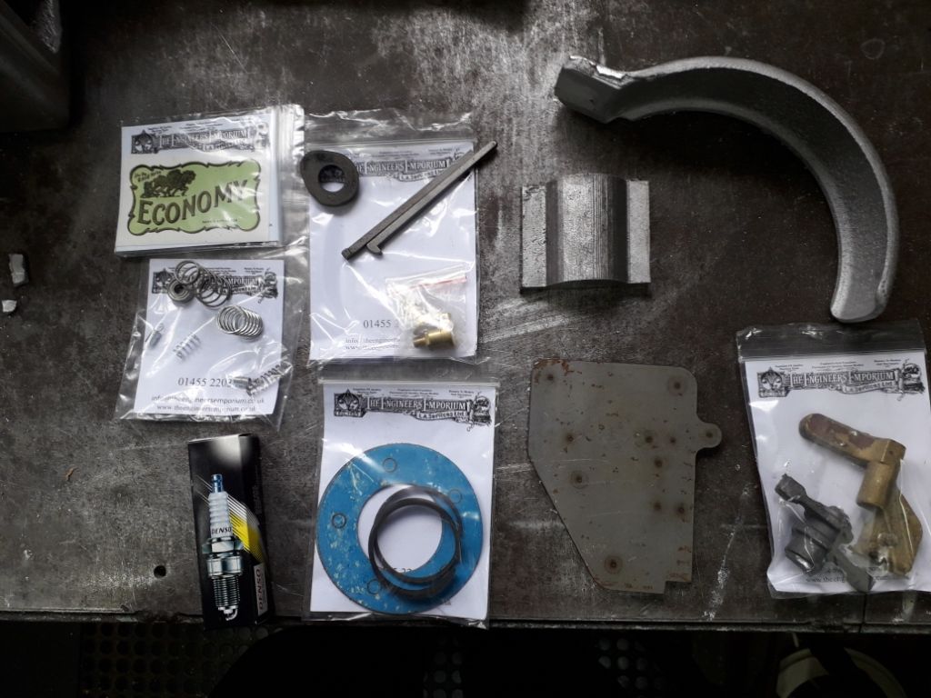
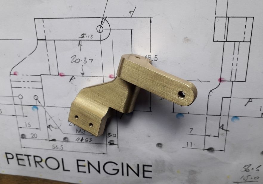
      I went up to collect it from EE on the 17th, had a tour around their rather impressive workshop with Adrian and came away with the basic and the extras kit. The basic parts are the two main castings – hopper and base now in aluminium, the two flywheels, a casting for the mains caps, an aluminium blank for the piston and a cast iron blank for the liner. The extras kit has the plate to mount the timing gears on, the timing gears, springs for the valves and governor, head gaskets, piston rings, a spark plug, valve rocker arm, crank guard, flywheel keys, main bearing oilers, a brass casting for the dummy magneto, a small bearing for the cam follower and the cam blank.

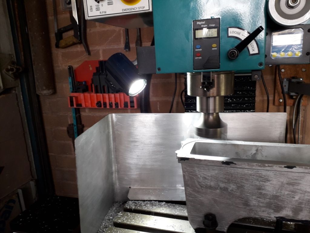
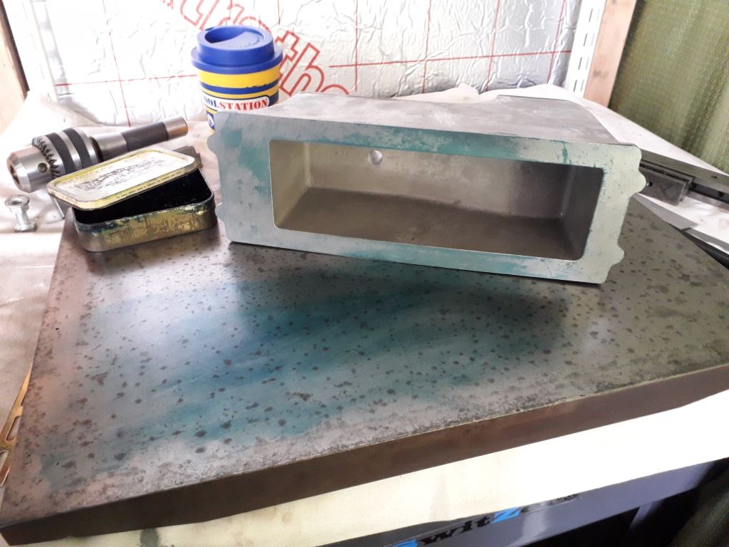
      Yesterday. after ordering some materials for the bearings, crank assy, con rod and miscellaneous small parts I had a few hours fettling the hopper and started on the base. I don't mind a bit of fettling, and it helps to get familiar with the castings before cutting metal. I hope to finish tidying the base up today and maybe start on the rocker arm and magneto mounting bracket.

      20.03.18 fettle..jpg

      20.03.17 extra parts.jpg

      Advert
      #31289
      Henry Brown
      Participant
        @henrybrown95529

        An occasional progress thread…

        #458699
        JasonB
        Moderator
          @jasonb

          Off to a good Start Henry.

          I was messaged by another member regarding a comment I made at the bottom of this page of Nick G's build thread and though it may also be of interest to you and other builders so thought I would post my reply here.

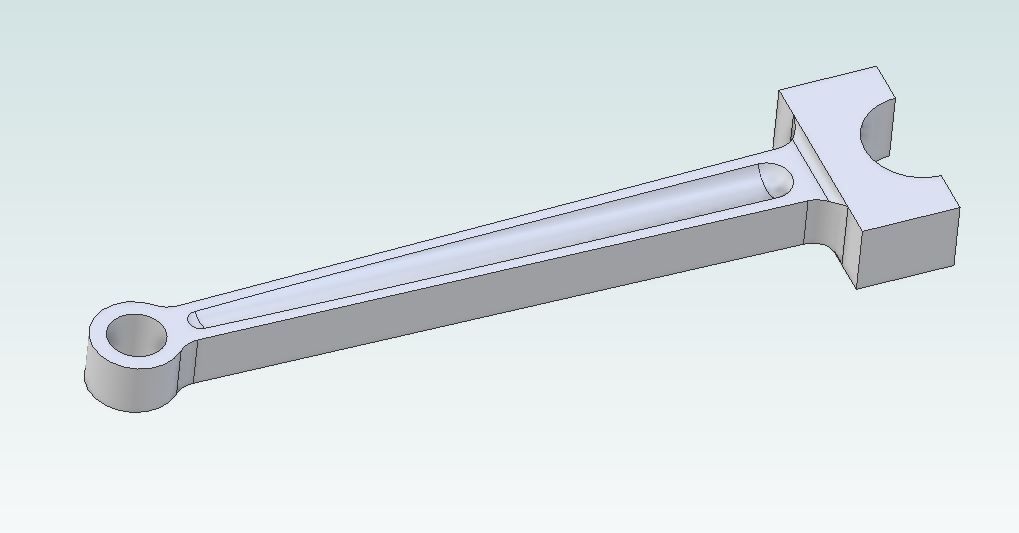
          The drawings show the central section of the conrod reduced to a tapering "H" section which would need to be done with something like a tee slot or woodruff cutter, Nick chose to do a parallel recess each side with a ball nose cutter, I commented that it is possible to do a similar rounded recess that tapers quite easily. This is Nick's

          And this a conrod from another engine done with a tapered shape

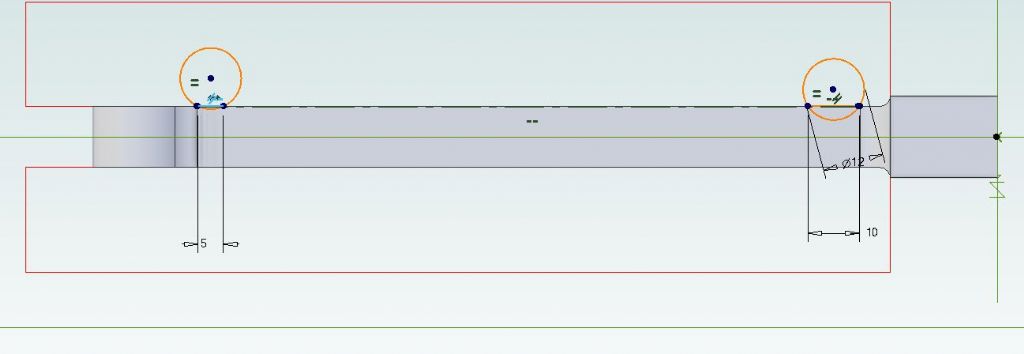
          So how is it done? Well a look at the drawing shows that the conrod tapers from about 15mm at the big end to 10mm at the small end and the thickness of the H is 2.5mm. So a simple bit of maths shows that t the big end the recess wants to be 10mm wide ( 15 – (2 x 2.5)) and 5mm wide at the small end (10- (2 x 2.5))

          With the help of CAD it is easy to draw the position of a cutter at each end of the recess and position cords of 10mm and 5mm level with the edge of the conrod. I chose to use a 12mm dia cutter

          crank web 1.jpg

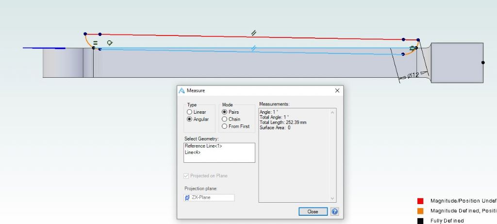
          From that a line can be drawn either Ctr to Ctr or tangental to the bottom of the two cuts and an angle measured and it's a nice round 1degree. well with the exact 15.74mm width at the big end it actually comes out to 1.01degrees for the pedants.

          crank web 3.jpg

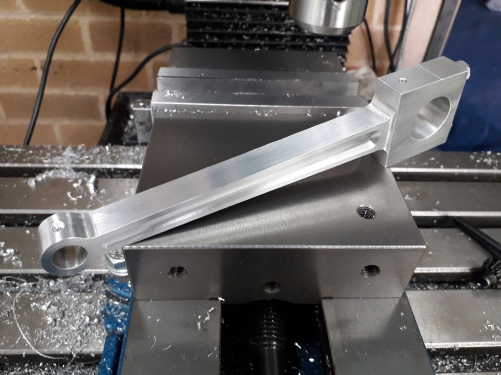
          Now unless you have CNC it is not easy to raise the Mill in Z as the conrod is moved in X. So if the work is set at an angle then it is a simple case of ramping or plunging the cutter into the work and then feeding in X until the width at the edges measured 2.5mm

          With luck it should come out like this

          crank web 2.jpg

          #458706
          Henry Brown
          Participant
            @henrybrown95529

            Thank you Jason, that's exactly what I wanted and all very clear, I guess I will have to look into sourcing a ball nosed cutter, fortunately I have a tilting angle plate that will do the job.

            Today's efforts involved machining the base. I was able to flycut the full width and when I blued it up on my surface plat it looked ok and was .0015" feeler proof so a good start for that part. I have also turned it over and have milled the "horns" for the mains, I'll machine the pad for the cylinder/hopper tomorrow.20.03.21 base mc1a.jpg20.03.21 base mc2.jpg

            #463349
            Henry Brown
            Participant
              @henrybrown95529

              Since last posting in this thread I've been concentrating on small parts as I would like to have all, or most, of these ready for when the big stuff is done. I've also been waiting for various bits of tooling that I didn't have…

              The striker arm made form a brass casting…

              20.04.02 striker arm.jpg

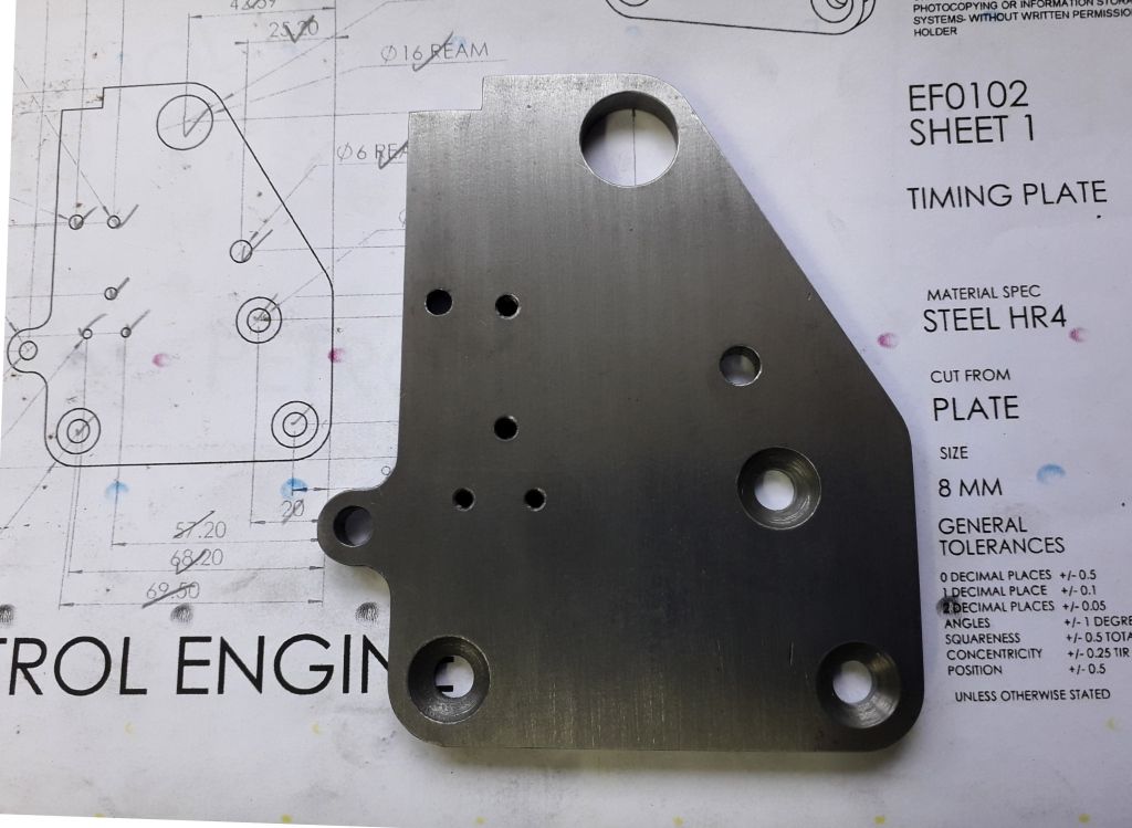
              The timing plate…

              20.04.05 timing plate.jpg

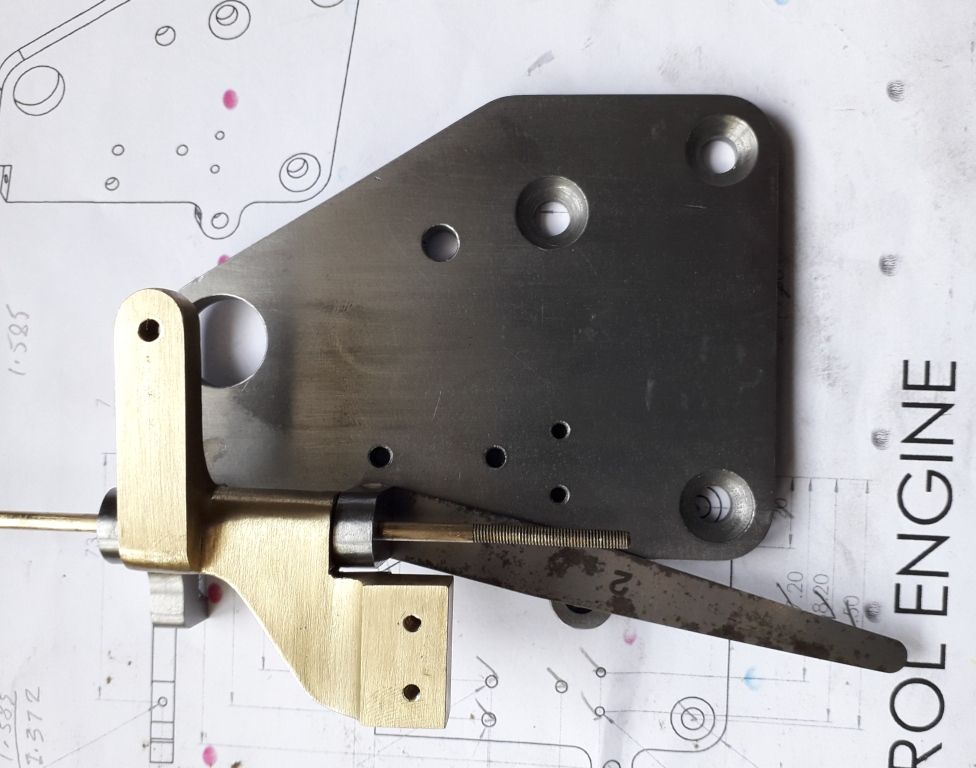
              And the assy of the timing plate, striker arm, the shim was for checking for free movement of the striker arm…

              20.04.07 striker arm timing plate assy2.jpg

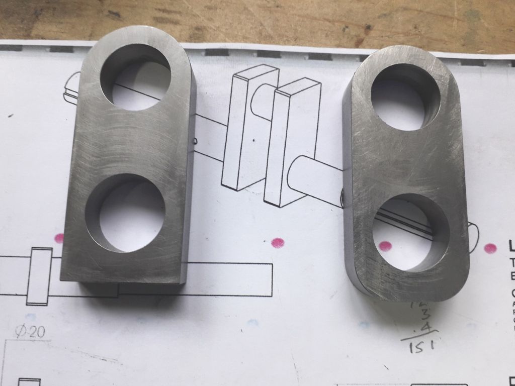
              The crank webs, just the two radii to put on the left one…

              20.03.29 crank webs.jpg

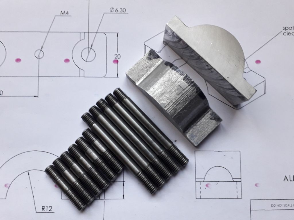
              These are a few of the studs and the two bearing cap blanks…

              20.03.25 studs and bearing caps.jpg

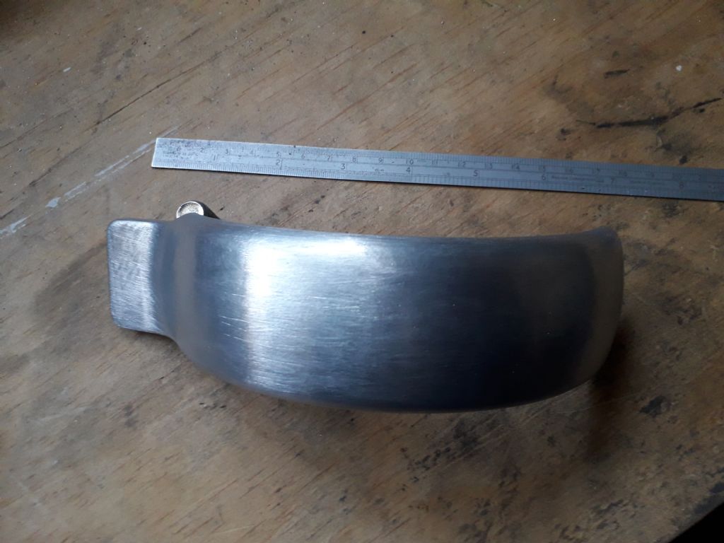
              And finally this is the crank guard…

              20.03.22 crank guard.jpg

              #468411
              Henry Brown
              Participant
                @henrybrown95529

                Time flies by! I've spent some part of most days since my last post making the smaller parts for my engine so I won't include the photos for these although I did take lots! More recently I've been having a go at the larger stuff…

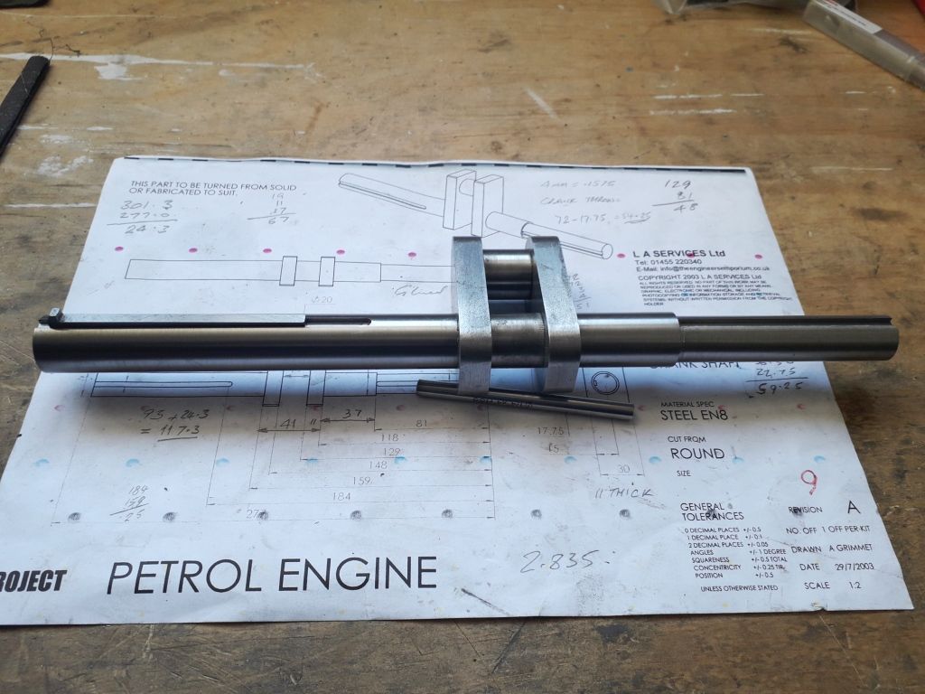
                20.04.13 crankshaft keyways.jpg

                I've used Loctite 638 to hold the four pieces of the crank together, I've also left the length of the ends longer because I would like to add a pulley on one side or the other to perhaps drive a water pump or something suitable. Just the part between the webs to cut out now.

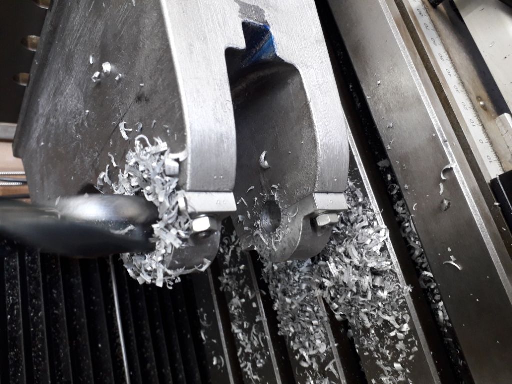
                20.04.15 base drilling.jpg

                I had to buy a larger angle plate to hold the base for the machining of the two main bearing supports and also had to make a bar to fit in my boring head to fly cut both inner faces of the supports so this took a little longer. This was due to the casting not being quite right here. Nick_G had to do the same, he built the outer faces up with JB Weld, however I spotfaced the outer faces and will make the outer flange of the main bearings wider to maintain the bearing width.

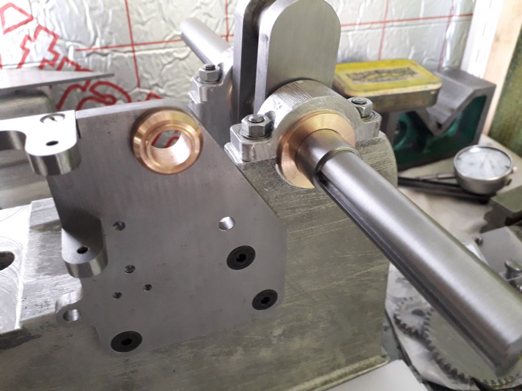
                20.04.20 base and timing plate with govenor bearing pressed in.jpg

                This was the start of some things coming together!

                20.05.01 conrod finished.jpg

                I fancied making the conrod next. The design is shown as steel but I thought I'd make mine from 6082 aluminium for two reasons, firstly it will be a somewhat lighter mass reciprocating if the thing ever runs and I quite like machining ali! In addition to the material change I also made the two studs fitted, I made the stud from silver steel and threaded each end M6, the holes in the conrod were drilled and tapped and reamed out to 7mm so the end cap is securely located. All the machining went well, I made a close fitting peg to fit in the little end to rotate around when machining its outer. Following help from JasonB I bit the bullet and angled the con rod by about 1 degree and both recesses worked out quite nicely. My next job will probably be the split big end bearing, a job I'm not really looking forward to!

                #478154
                Henry Brown
                Participant
                  @henrybrown95529

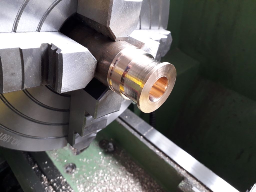
                  Over a month since I posted an update! Still fiddling about mainly making the little bits for the engine but have nearly sorted the head assy. As mentioned last time I had the split big end bearing to make which turned out well thanks to following advice seen on this forum, I did scrap the first one due to operator error on the lathe though…

                  20.05.03 big end brg 1.jpg

                  20.05.03 big end brg 2.jpg

                  The joints of the two halves were skimmed and soldered together using solder paste (something I'd not come across before – I'm learning so much on this build!) The outside was finished leaving the bore to be finished on the mill when fitted into the con rod.

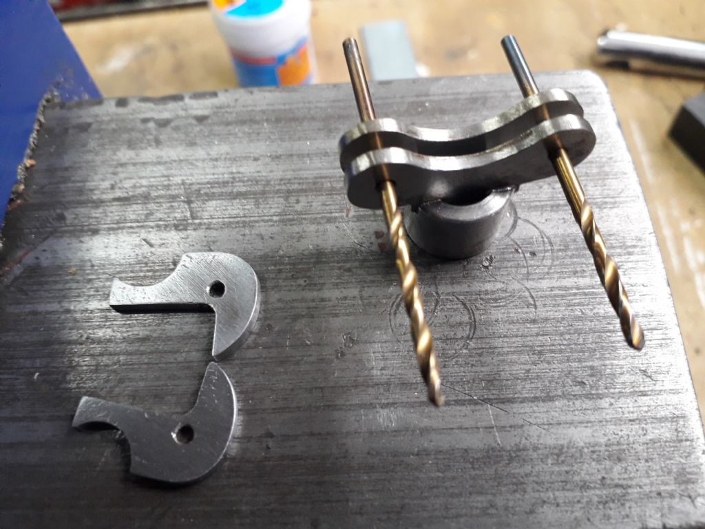
                  I then turned my attention to the govenor assy, the body was machined and the arms made by profiling them on the mill and then cutting them out and filing the radii etc. The ears were then soldered to the body using a couple of drill to line them up.

                  20.05.10 govenor wings 1.jpg

                  20.05.10 govenor wings and body soldered together.jpg

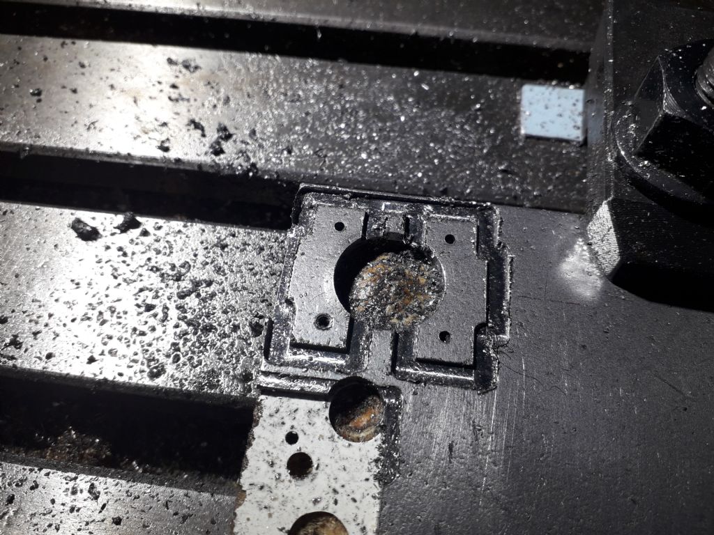
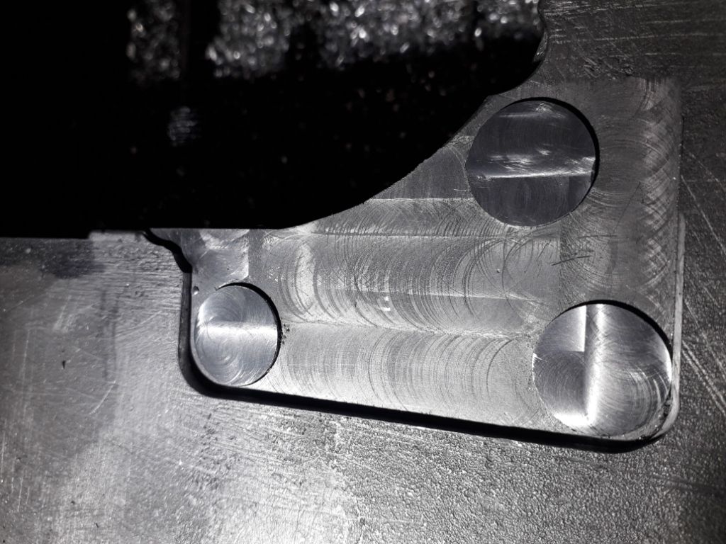
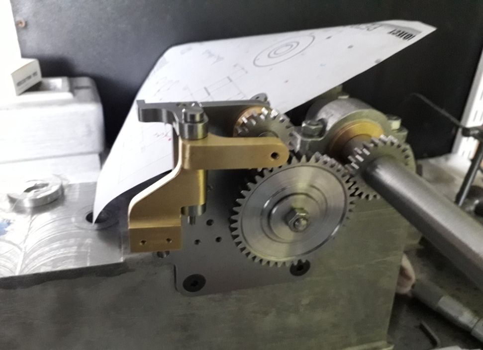
                  I have pretty much made ll the parts for the timing assy previously so now it was time to set it all up on the base as I had the crank fand bearings finished. I was disappointed to see that there was quite a bit of backlash between the crank gear and the intermediate timing gear and the whole assy seemed to be set back too far into the base. I pondered it for a day or two and decided it wasn't good enough so designed some top hat plugs to correct the location of the plate. I decided that I needed to move the plate towards the crank by 0.5mm and up by 1mm, the base was set up again and the three 1/4BSP (I didn't have a tap any finer that suited!) threaded holes put in on the new centres. The plugs were fitted using Loctite 638 and then skimmed to 1mm above the old face.

                  20.05.25 base salvage 1.jpg

                  A trial fit of the timing plate assy then all looked pretty good. I should just say that when I put the base up to do the mods I checked what I'd done to the drawing and it was fine, I had wondered if I'd made a cock-up!

                  20.05.14 timing gears 1.jpg

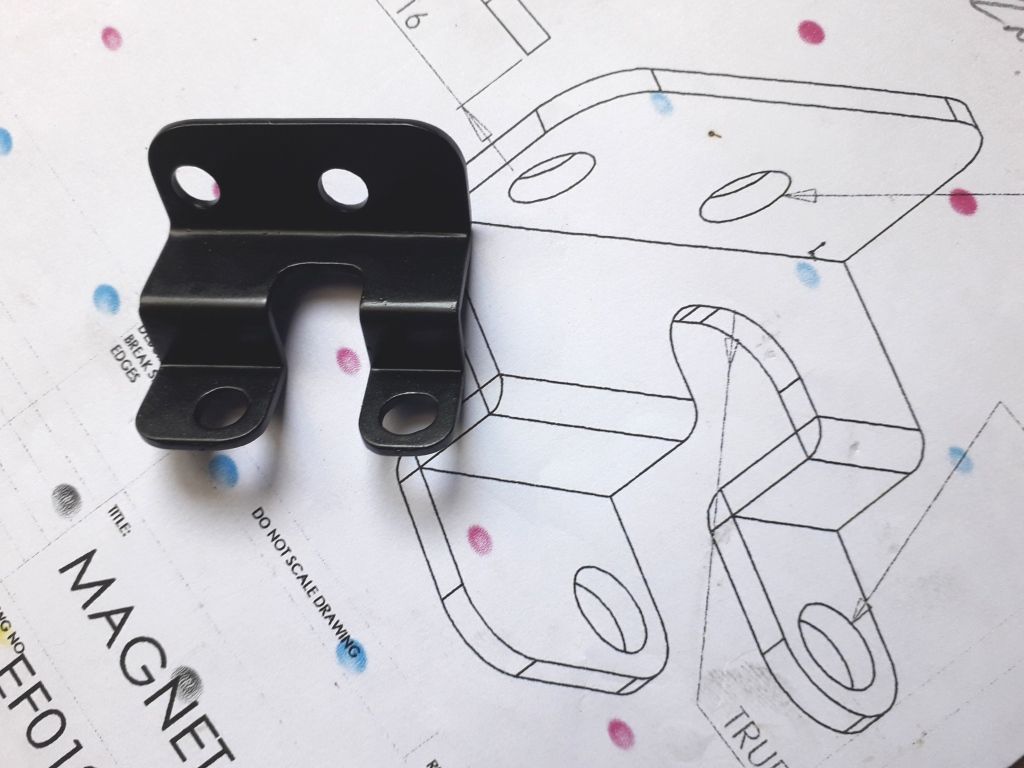
                  I fancied a bit of tin bashing next so made the bracket for the dummy magneto out of a bit of steel plate I had lying around and sprayed it up satin black.

                  20.05.17 magneto bracket.jpg

                  Part two to follow as I've exceeded the maximum characters for a post!

                  #478155
                  Henry Brown
                  Participant
                    @henrybrown95529

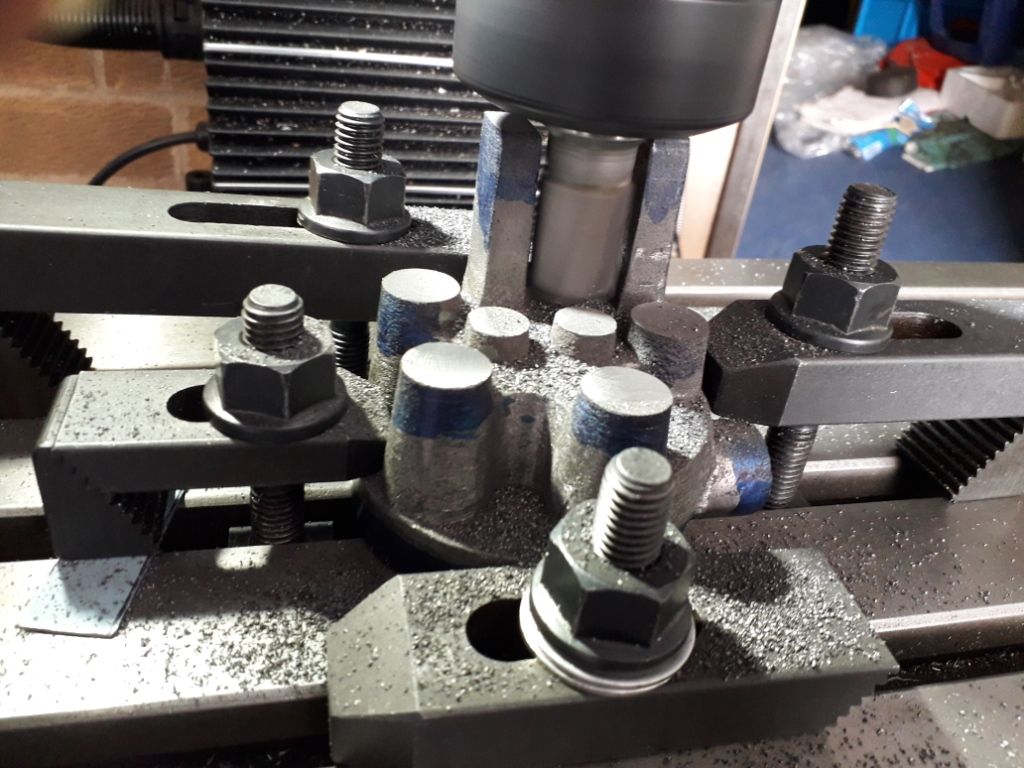
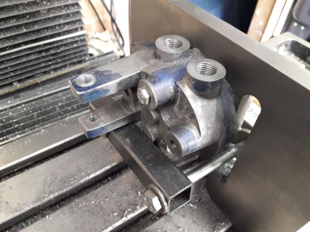
                    My attention was then turned to the cylinder head, I firstly skimmed the combustion side to give a stable base to sit it on in the mill to machine the various bosses.

                    20.05.18 cylinder head 3.jpg

                    It must be said that the casting was of excellent quality, it machined beautifully and gave no problems with material allowance.

                    20.05.19 cylinder head 2.jpg

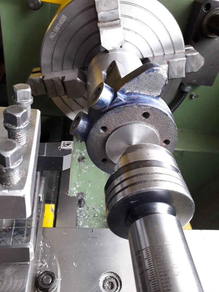
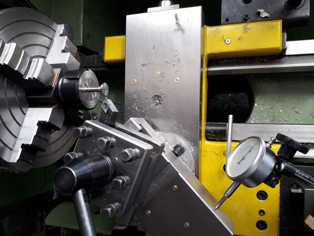
                    It was then over to the lathe to do the faces that mate to the cylinder and liner using the fixture I'd previously made based on what others have done.

                    20.05.21 head second set.jpg

                    I didn't machine the valve throats on the lathe, I found it was easier to go back to the mill and bore them on there, I used a 90 degree countersink cutter to form the valve seats..

                    The valves were next in line, I turned the shaft end first. They were then mounted in a square Stevenson block set in the 4 jaw chuck that was set up using a piece of silver steel in the same collet that would be needed for the valve stem and the head end finished. I checked the first off against the seat in the head and it blued up a treat so carried on to the second.

                    20.05.28 exhaust valve machining.jpg

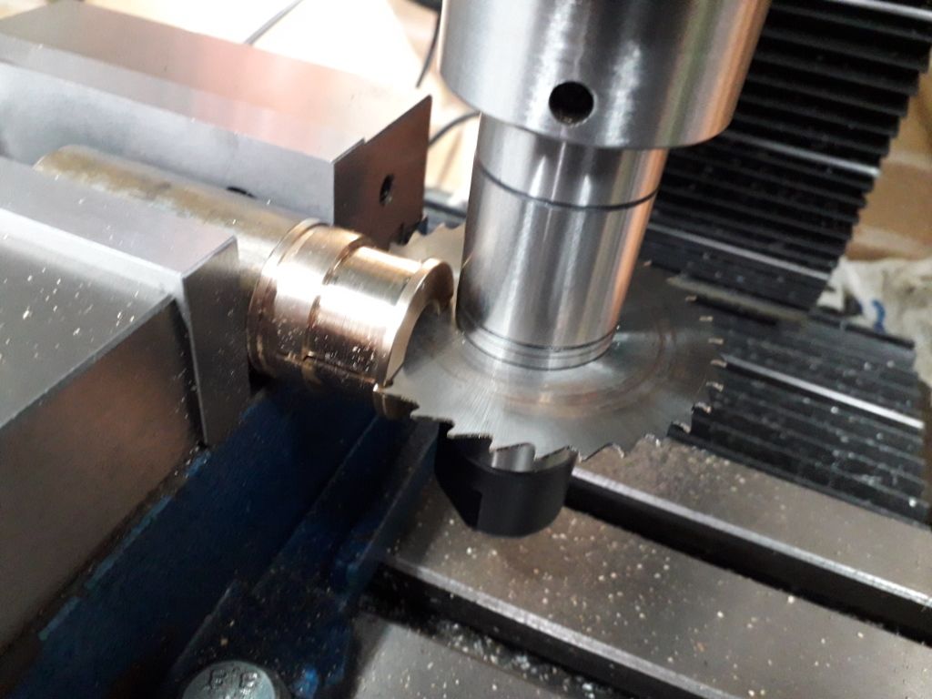
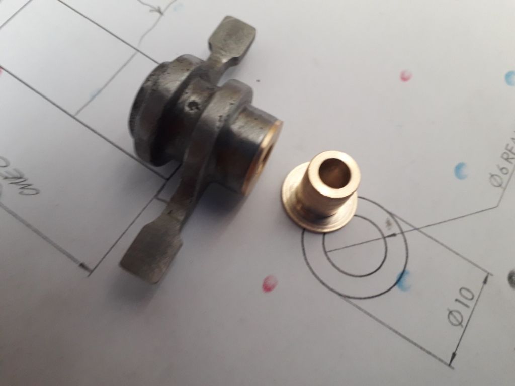
                    I had previously done some work on the rocker arm and it was now time to make the bushes. I deviated a little from the drawing as I felt it would be beneficial to have some bearing for thrust on either end, the drawing is for a plain bush that relies on the CI rocker bearing against the CI of the head, perfectly ok in this application but I felt this would be better. A top hat bush was pressed in from each end…

                    20.05.29 rocker bushes.jpg

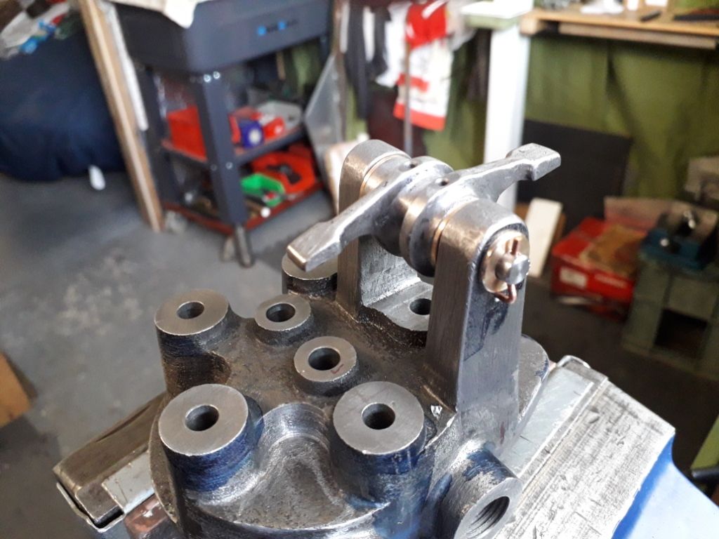
                    Of course a trial fit was in order. I guess I will need to think about a suitable paint for the head and rocker in due course…

                    20.05.30 rocker arm on cylinder head.jpg

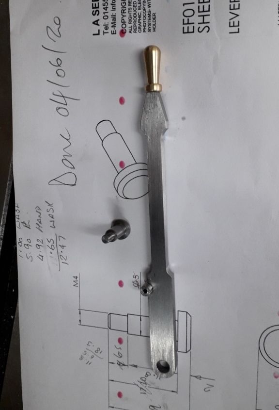
                    Back to the little bits again, this is the speed control lever, the little brass knob added a bit of bling!

                    20.06.03 speed control lever.jpg

                    I had planned to start on making the cylinder liner but the material (cast CI bar) that was supplied as part of the kit had some inclusions in, that is being replaced so will probably be the next job.

                    #504571
                    Robert Askew
                    Participant
                      @robertaskew15193

                      Just received my castings for my economy engine

                      they all look to bad apart from the water hopper

                      it looks like I might struggle to clean it up miss match from one side of casting of about 2mm

                      anyone got any pics of there’s

                      all the ones I have seen on Internet look far better than mine

                    Viewing 9 posts - 1 through 9 (of 9 total)
                    • Please log in to reply to this topic. Registering is free and easy using the links on the menu at the top of this page.

                    Advert

                    Latest Replies

                    Viewing 25 topics - 1 through 25 (of 25 total)
                    Viewing 25 topics - 1 through 25 (of 25 total)

                    View full reply list.

                    Advert

                    Newsletter Sign-up