Eccentric Turning

Advert

Eccentric Turning

Home Forums Stationary engines Eccentric Turning

Viewing 16 posts - 1 through 16 (of 16 total)
  • Author
    Posts
  • #68380
    Alan Worland 1
    Participant
      @alanworland1
      I have machined 95% of my Stuart No 4 castings and it appears I have have left the best bit till last!
      I have the reversing gear castings which contains a double eccentric part. Obviously the eccentric ‘lobes’ are timed to work the valve gear efficiently and they therefore have a specific angle between them but I am not sure where to start after putting the bore through – any body got any ideas?
      Advert
      #3088
      Alan Worland 1
      Participant
        @alanworland1
        #68382
        JasonB
        Moderator
          @jasonb
          I would leave the bore until last. You can mark the centres of the two throws onto the end of the bar or plugged casting, lightly dot punch and use these marks to set up in the 4 jaw to maching them. Once done set up to machine the bore.
           
          I’m not totally familiar with the part but if its a hard to hold casting it may be better to bore first, fit onto a mandrel then mark the throws onto the end of the mandrel and then set up in the 4jaw.
           
          J
           
          Edit just looked, its from a bit of bar with two eccentrics so the first method I suggested, provided stuarts supply a long enough bit to get hold of.


          Edited By JasonB on 13/05/2011 20:45:25

          #68387
          Ramon Wilson
          Participant
            @ramonwilson3
            Hi Alan, Glad to hear it’s coming to fruition.
             
            This is not to disagree with Jason but you may find it easier to make up a simple clamp plate to hold the boss mounting it on the face plate to machine the eccentrics. I find this much easier than using the four jaw as it eliminates any possibilty of axial mis-alignment.
             
            Here’s a couple of pics from the Racer file. The plate need not be anything special – as you can see this one has had several uses. The slot was wide enough to allow the clamp bolt to nip the part securely despite the holding bolt.
             
             
            This is the backplate but shows the principle. I do not have any pics of the ops but have used this method before for turning eccentrics and it works well.
             
            Hope you are well –
             
            Regards – Ramon


            Edited By Ramon Wilson on 13/05/2011 21:11:55

            #68388
            Alan Worland 1
            Participant
              @alanworland1
              Thanks for your reply, so would you rely on the casting being accurate enough to do this?
              #68400
              Ramon Wilson
              Participant
                @ramonwilson3
                Hi Alan, No, I don’t think so unless the boss area was extremely well cast ie quite round and parallel. It really ought to close on a machined surface for the best grip – the better the fit the less the clamp screw has to turn to exert sufficient force.
                 
                Looking at an image of a No 4 it appears this eccentric casting has a boss. You really need to turn that to give a uniform surface for the clamp to grip on. For that, it will be the four jaw or clamping to a small faceplate. Personally I think I would be inclined to bore it at this stage too. The boss is then your datum. Once you have that it is surprising how little clamping pressure will be required to grip the part for the remaining turning. As Jason has said you will need to mark out the centres of the eccentrics but setting them to run true with this method is easily accomplished by moving the clamping plate on the face plate.
                An alternative, if you have the means, is to mark two lines on the clamp plate at the correct angle between the two eccentrics . A mark on the boss that will be visible once in the clamp plate is aligned with the first mark and clamped up. The plate is set up to run true to that eccentric. Once machined the boss can be rotated to align with the second mark and the second eccentric machined without having to reset the plate.
                 
                Hope that helps a bit further
                 
                Regards – Ramon
                 
                #68408
                mgj
                Participant
                  @mgj
                  You don’t have to be that accurate. Don Ashtons book says that the lead of a launch link engine is typically between 21?? and 27 deg. And if you are a bit out, you can restore the timing by shaving a bit of lap off. (or adding a bit) Not ideal, but it will still run fine. On my traction engine I had too much lead even though I set (keyed as per drawing) the eccentrics very accurately to 21 deg of advance. I could have shimmed the rods, but it was easier in the installation to alter the valve. Wicked lazy I know, but it runs perfectly. – so well that it will just tick over under no load on the tiniest leak through the regulator (if you put it in gear). Critcise the regulator if you will, but the rest is pretty good!.
                   
                  So if you know what the lead is, its more important to get it the same forwards and reverse than actually to a given amount, though perfect is best of course.
                   
                  I did a Stuart Launch engine and I am assuming these are the same type with both eccentrics and the boss all cast as one unit? Marked the crank bore on the casting and bored/reamed that.. Marked the first eccentric centre. Put the thing in a dividing head and rotated the assy to the right offset to mark the second eccentric centre. Now you have 2 pop marks to dividing head accuracy one in each eccentric, its a simple 4 jaw job, settiing the 2 popmarks true in turn using the normal 2 centre technique with the assembly mounted and locked on a dummy crank.
                   
                  If you don’t have a dividing head, then draw the angle 4x full size with a protractor and shrink it in a scanner. That’ll come out pretty accurate, and one can mark out from that.
                   
                  PITA of a design. If you get bored with it, just make the 2 eccentrics separately, and set fwd and reverse independently to zero lead in full gear by moving the eccentrics as normal. Unless you intend to cross the rods when a smidgen of lead might be useful, since it will reduce towards mid gear. Thats what I shall do with the next TE. Not cross the rods of course, but set the valves by rotating the eccentrics – because there is a far better chance of getting better valve setting, and you can eliminate to a degree errors introcuced by small dimensional inaccuracies.(perfect being better!)
                  #68413
                  JasonB
                  Moderator
                    @jasonb
                    Ramons method sound fine but you will have to plug the machined bore so the throw centres can be marked out if you bore it at the same setting as the boss.
                     
                    We must have been looking at different engines as the one I looked at had the eccentrics in steel so I assumed a good length of bar would be used so the chuck jaws would give good axial alignment but if you only have a short boss to grip mounting in the plate or on a mandrel will keep it all in line.
                     
                    J

                    Edited By JasonB on 14/05/2011 09:18:52

                    #68431
                    Ramon Wilson
                    Participant
                      @ramonwilson3
                      Hi Jason,
                      Given Alans first post I assumed from the image I looked at that this was a casting too but I agree that machining it from scratch from solid bar would perhaps be a bit easier from the holding point of view. However having used this method over that of using the four jaw on several occasions I have found it much easier for setting up on the lathe itself so even then personally I would be inclined to still use this method of holding to machine the actual eccentrics. As always though it’s down to individual choice
                       
                      In itself mgj, the method is not to achieve accuracy per se but to give a simple means of workholding of a fiddly little component. The fact that accuracy ensues is a bonus. Once clamped in all is in alignment, and agreed – just as much as holding on a mandrel offset in the four jaw but held much more firmly than with a single grubscrew. The plate of course can be recycled for similar tasks.
                       
                      In the end I guess it’s very much a case of ‘Yer pays yer money’
                       
                      Regards – Ramon
                       
                      #68436
                      mgj
                      Participant
                        @mgj
                        You could well be right. – I could see the plate holds the boss well. I often use a grub screw and 603 retainer, and then heat to release – I guess I’m too lazy to make a plate! (I will put that in the memory banks against the day, because it will come. A t version of such a plate could be used for turning crankshafts at reduced overhang where one wouldn’t want grub screw marks.)
                         
                        Jason – dead right, that the same setup as mine, just scaled up a touch. That pair of eccentrics is/was a single casting!)
                         
                        Perhaps my passion for being accurate in this case was because I had a 2 cyl engine, so sameness of the 2 components angles was very important.
                         
                        Doing it again I certainly would just make 2 separate eccentrics out of bar. That design is very awkward indeed to get all to thickness, machining one disc behind the other. Or else you have to turn it round and reset. (The design I had was just 2 eccentrics and a boss, like a couple of coins one on the other, and a small boss 3/4″ long in total if I remember right. Anyway that sort of size so there was no real holding length or boss – hence the mandrel suggestion)
                         
                        If one didn’t want to have the units separate when installed I’d still make them separately and then pin them together at the right angles.

                        Edited By mgj on 14/05/2011 12:15:05

                        Edited By mgj on 14/05/2011 12:18:30

                        #68548
                        Alan Worland 1
                        Participant
                          @alanworland1
                          Thankyou all for your help!
                          I haven’t got a photo of the part concerned but it is indeed a casting with a shortish boss and yes Ramon I would have machined the boss first to enable the part to be accurately held.
                          My comment on the casting accuracy was about the actual ‘timing’ of the eccentrics as the look ‘about right’ as a casting but I would expect errors to be introduced when I tried to get the eccentric diameters to run true
                          mgj your suggestion (I have a degree marked rotary table) sounds a potentially good way of getting the cams at the correct angle to themselves
                          I think I will make a start by machining the boss then put the bore through, which could be temporarily plugged to mark the eccentric centres.
                           
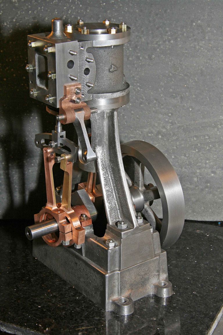
                          Hopefully an image of what I have been up to!

                          #68553
                          Ramon Wilson
                          Participant
                            @ramonwilson3
                            Hi Alan,
                            That s a very nice piece of workmanship, not that long before you paint it eh?
                             
                            I see now what you meant about the casting being accurate – I thought you were referring to the actual gripping on the raw casting.
                             
                            Another benefit of using the clamping plate is that you can still use the plate to set up on the R/T setting the bore true then moving over the relevant throw to mark the centres before transfering back to the face plate with the part still locked in situ. Whatever, good luck with it whichever way you go about it as it’s not an ‘easy’ component that’s for sure but from what we’re looking at so far you won’t have too much difficulty
                             
                            Regards – Ramon
                            #68561
                            Alan Worland 1
                            Participant
                              @alanworland1
                              Thanks Ramon, I have enjoyed making it – but no paint till its been JB Welded!
                              #68564
                              mgj
                              Participant
                                @mgj
                                It is a nice piece of work
                                 
                                Alan its a horrible design of casting, because if you turn it round to turn the other eccentric, then you lose the centre pop and that critical relationship. So I turned the 2 from the same side. To retain the valve rods I cut a groove in the eccentrics and machined the rod ends with a raised internal “fin”. You could just use a circlip and put grooves in both I suppose.
                                 
                                The trick is that it doesn’t matter where the first eccentric to be turned is, in relation to anything else. What matters is the relationship between the eccentrics. “TDC” can be found with a dial gauge, but with an eccentric you need to be a touch more careful than with a cam.
                                 
                                Its a horrible bit of design, and as I said, knowing what I know now, I’d make 2 eccentrics and pin them later into 1 unit, or even key them onto the crank, once I hade the valve timing properly adjusted.

                                Edited By mgj on 15/05/2011 23:27:01

                                #68566
                                Alan Worland 1
                                Participant
                                  @alanworland1
                                  Horrible is a good word! I have already machined a groove in the bore of the eccentrics so I need to leave a bit on the eccentrics to locate in it.
                                  If it all goes wrong I will turn to a diameter and make two to pin/secure on as you describe.
                                  #68579
                                  John Olsen
                                  Participant
                                    @johnolsen79199
                                    I have a certain number of Stuart pieces “left over” because I decided it was easier to machine them from a larger piece of stock or in some other way, like the suggestion of making two eccentrics rather than one given above. On a somewhat larger engine than this, I was able to make the two eccentrics, set them on the shaft using a grubscrew, then mark out and cut the keyways to key them on. Once they were keyed the grubscrews were superfluous. I’m not sure if the No 4 is quite big enough for that to be viable.
                                     
                                    regards
                                    John
                                  Viewing 16 posts - 1 through 16 (of 16 total)
                                  • Please log in to reply to this topic. Registering is free and easy using the links on the menu at the top of this page.

                                  Advert

                                  Latest Replies

                                  Home Forums Stationary engines Topics

                                  Viewing 25 topics - 1 through 25 (of 25 total)
                                  Viewing 25 topics - 1 through 25 (of 25 total)

                                  View full reply list.

                                  Advert

                                  Newsletter Sign-up