DRO’s

Advert

DRO’s

Viewing 24 posts - 26 through 49 (of 49 total)
  • Author
    Posts
  • #102532
    Gone Away
    Participant
      @goneaway
      Posted by Clive Hartland on 02/11/2012 17:13:52:
      The only thing you have to do is measure any space you want to fit the scales then look at the specs. and decide which size you need to buy.

      I don't understand that statement Clive. It seems to suggest selecting the scales by the available space to mount them.

      What you need to do is check/measure the end-to-end travel of the axis concerned and select a scale with a measurement length slightly larger. Any smaller and you are either restricting the travel of the axis or (more likely) you will wreck the scale by overtravelling it.

      Once you've selected the scale you then have the (sometimes thorny) problem of fitting it into the space available.

      I'm referring here mostly to a mill but the principle should apply to a lathe as well (although some – eg cross-slide – travel may be a bit "open ended" and you might then want to fit a positive stop. …..just thinking out loud haven't go around to doing the lathe yet).

      Advert
      #102533
      JasonB
      Moderator
        @jasonb

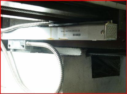
        Sid you also need to consider the depth of the scale if it is to fit into the available space, on the X3 that Clive and I have it would be very difficult to mount a standard sized scale on the Y-axis so you need to use the smaller profile GS-500 scales. This size scale is also better for the X-axis.

        As you can see I only ave a few mm below the read head so a bigger scale won't fit unless its is spaced a long way off the machine

        yaxis.jpg


        Really depends on the mill/lathe and is why Clive says you need to measure more than just the length

        J

        Edited By JasonB on 02/11/2012 17:48:53

        Edited By JasonB on 02/11/2012 17:50:36

        #102535
        Robin teslar
        Participant
          @robinteslar

          [ BTW – you seem to have, deliberately or accidentally, added a background colour to your text – in this case grey so it isn't showing against the normal background (but does in the emailed version), If you are experimenting in that direction, please, please reconsider. There's already one person around here doing it (with a sickly yellow that I presume he considers kewl) and I hope it doesn't catch on. Most people set up their browsers with text and background colours that they are comfortable with and don't need others forcing their own preferences.

          Sorry that was an accident, I didnt notice it at the time, but was cut and paste from a msg

          Robin

          #102543
          doubletop
          Participant
            @doubletop

            You dont need the more expensive KS500 scales for the SX3 the standard size scales are fine. But you can use them if you want to.


            I did a bit of a write up here. **LINK**

            Althouh the title says X3 I have an SX3. I assume the SX3 and X3 tables are the same. If you have a long table from ARC just select a longer scale.

            Hope that helps somebody

            Pete

            Edited By Doubletop on 02/11/2012 19:38:17

            #102545
            Clive Hartland
            Participant
              @clivehartland94829

              Sid, the 63mm scale will not fit in the space shown on Jasons Pic. Even then the 45mm depth scale is a really tight fit and I may have to mill off 2 or 3mm of that base plate.

              The GS-200 series are only 32mm deep and will fit fine and I may yet have to exchange for one of them.

              Luckily I have a friend who has a Schaublin Mill and I have access to it so that may be the way I will go as I have to dismount both X and Y slides to mount the X slide anyway.

              For any one contemplating fitting these slides buy a small piece of Alu. angle about 5mm thick as the Cast plates and angles supplied are not too good and I had to machine the surfaces as they were not flat and caused the scale to bow when the screws were tightened.

              Clive

              #102553
              doubletop
              Participant
                @doubletop

                Its tight but not impossible. You'll see from my pic the scale cover is a couple of mm below the top of the table. And remember the reader is fixed and the scale moves with the table so that small gap between the reader and the Y jib plate isn't an issues as they don't move relative to each other. No machining was necesary.

                I've just had a look at Jasons pictures. I requested the D covers which come with a 10mm thick backplate. That, and the size of the larger scales, stands off the whole assembly so the reader now secures on the back face and not the top face of the casting. compare the two photos.

                Otherwise pay the extra $20 and get the smaller scales. Neither option is wrong

                Pete

                #102555
                Gone Away
                Participant
                  @goneaway

                  Sorry, Clive. When you referred to "size", I assumed you were talking about the length and it seemed strange to select a length based on the room available for mounting.

                  All clear now.

                  > I have to dismount both X and Y slides to mount the X slide anyway.

                  Ouch!

                  #102569
                  Gone Away
                  Participant
                    @goneaway

                    If I understand you guys correctly, the dimension you are talking about is from the top of the scale to the bottom of the read-head. In that case, on my Ditron scales, this is 50mm. (I didn't realise when I bought them that they had a 39 mm version for not much more money. That might have been easier to mount – but I managed).

                    This is how I mounted the X-axis to my WM14-WM16 (about half way between) lookalike. There's plenty of room in this case but I don't know how this machine compares with the X3:

                    x-axis dwg.jpg

                    Since the scale is mounted "upside-down" I installed an extra wiping seal at the top (regular house-door seal). See other pictures. No machine disassembly was involved (although I didn't have the power feed at that time).

                    The Y-Axis I simply mounted using the front table slot (that normally carries the travel-stops …. I discarded those). For the Z-axis I had to make up a special bracket (relatively complex to maintain stiffness)

                    x-y-1.jpg

                    x-y-2.jpg

                    z-1.jpg

                    #102574
                    Clive Hartland
                    Participant
                      @clivehartland94829

                      The X3 has vertical sides to the base casting and the slides are vertical sided, its just the space below the table for the X scale that is the problem on the X3. Jason has done his and I am awaiting delivery of my scale which should be here on Mon/Tues. Then I can see how it will fit the available space.

                      clive

                      #102577
                      doubletop
                      Participant
                        @doubletop

                        I'm out in the workshop now and from Clives comment realise that Jason's pic is the Y axis. Yes it is tight but using the D covers with the back plate and some simple standoffs from 19mm ally I did my Y like this

                        Pete

                        #102578
                        Gone Away
                        Participant
                          @goneaway
                          Posted by Clive Hartland on 02/11/2012 23:13:35:

                          The X3 has vertical sides to the base casting and the slides are vertical sided, its just the space below the table for the X scale that is the problem on the X3.

                          Mine has the angled sides to the base but could they just as easily have been vertical for all the difference it would have made (the moving head bracket could have been ever-so-slightly simpler).

                          I'm likely missing something on X3 from Jason's picture.

                          #102579
                          Gone Away
                          Participant
                            @goneaway

                            er …. red face …. I got my X and Y confused in my message with the pics up there.embarrassed

                            #102583
                            JasonB
                            Moderator
                              @jasonb

                              You may have missed this bit in my post "so a bigger scale won't fit unless its is spaced a long way off the machine"

                              I wanted to keep the scales as close as possible to avoid any risk of movement from having several bits of alloy angle lashed together. (not saying yours is a lashup Pete)

                              The smaller scale on the back of the table does give a decent surface to put a square against or clamp across the table.

                              Having the scale on the back is why the table needs to come off for drilling access and allows the front stops to be used. Its not card to take off just keep winding teh handle until the screw comes out of the nut and slide it off.

                              I think with all these installations there is more than one way to skin a cat, you just need to assess what suits you and your machines.

                              J

                              Edited By JasonB on 03/11/2012 08:10:46

                              #102633
                              Gone Away
                              Participant
                                @goneaway
                                Posted by JasonB on 03/11/2012 07:48:42:

                                I think with all these installations there is more than one way to skin a cat, you just need to assess what suits you and your machines.

                                Oh, absolutely …. and the more examples the better for people coming after.

                                On my mill, the only thing that limits the cross (Y-axis) travel is the table crashing into the column. Putting the scale on the back of the table would have reduced the cross-travel which was not an option for me. I'd never found the table stops on the front to be particularly useful so their loss was not an issue and mounting the X-axis scale was pretty simple and direct using the slot and existing holes. Bit of a no-brainer in this case.

                                (Although I later bought a power feed – you can see it in the pics – which uses the front slots for it's limit-stops. I'm running without the stops at the moment but the article in the latest MEW, while not directly applicable, has started me thinking …..)

                                The most difficult mounting for me was the Z-axis scale which necessitated a two part cantilevered bracket which, as you say is best avoided if practical for reasons of stiffness. It can be done successfully though, if you need to, by machining custom "structural" brackets designed for stiffness rather than simply using what comes to hand. The Z-axis mount took me probably 8 hours to machine (a fast machinist I ain't) but I think is worth it for the flexibility (in locating the scale not in the bracket smiley ) it gives you.

                                Edited By Sid Herbage on 03/11/2012 14:33:08

                                #102678
                                Clive Hartland
                                Participant
                                  @clivehartland94829

                                  To John S,  

                                  Mention was made earlier about scales on a Lathe and the fact that the tool taking a cut took twice the depth of the cut off the dia.

                                  I have just been reading the book of words for the Display unit and it has a section for use on a Lathe, here it says that you set up the work and take a cut to a set dia. (Perhaps 22mm) then at that stage you set Absolute Zero on that scale, then you can use that scale setting to turn to the dia. you require.

                                  There is also a function where you can set it to read Radius or Diameter readings. So it is as I thought, take a cut, reference it and work from there. Whether it is set to radius or Diameter you know from the readout what you are taking off against your final diamter.

                                  Clive

                                  Edited By Clive Hartland on 03/11/2012 20:34:23

                                  Edited By Clive Hartland on 03/11/2012 20:35:08

                                  #102681
                                  doubletop
                                  Participant
                                    @doubletop

                                    On my readout the 1/2 button switches between radius and diameter. There is no indication what you are in so I do as Clive suggests and make a trial cut to find out. It will keep your last setting but a case of don’t assume check.

                                    I've also found that the if you have a scale on the saddle and top slide the "integrate Y&Z" function the "ARC" button on mine. sums the two scales on the Y readout so you can move the saddle and top slide and maintain reference along the job. This expects cross slide on X, top slide on Y and saddle on Z. If you want a DRO on the tailstock I'd suggest a means of switching the saddle and tailstock connections to the Z readout

                                    #103485
                                    Robin teslar
                                    Participant
                                      @robinteslar

                                      Hi Guys

                                      I had a TOWIE moment and lashed out £23 on Ebay (The only way is ….) and have received a used Mitotoyo dail guage model 543-180 IDC. It looked a little battered but the Seller assured me that it was fully working, no jitters or rough spots and recent new battery. Sure enough it does and resolves to 0.00001 in (what!!!). Its a classy piece of kit costing nearly 100quid new (which I would never have afforded. So I am a bit chuffed. I intend to try it out on the cross slide of my Myford and use it as a digital scale (which had excited al lot of comment recently about the difficulties of budget calipers etc.

                                      As the whole gauge is well sealed against outside, it should perform well, I think, worth a gamble

                                      I noticed that there was a 6pin socket for a lead. I ebayed and found the lead would cost more than my gauge, so I don't think I need an external readout

                                      Way to godont know

                                      Robin

                                      #103547
                                      Captain Biggles
                                      Participant
                                        @captainbiggles

                                        For those interested in fitting magnetic encoders to their lathes / mills (etc), I have just done exactly that to my 3-in-1 machine using the following parts from the following vendors (no links / connections to businesses implied, just a happy customer with the experience of it all working together.)

                                        1um Renishaw / RLS readheads were bought from eBay from America, chap has plenty to offload and is open to offers. Service and knowledge is excellent. **LINK**

                                        Scale and rails can be bought from Allendale, here: **LINK**. I used the 2-part scale support, but the only disadvantage is that the screws to mount it to your table / bed etc are under the middle of the scale, so once the scale is in place it can't be adjusted.

                                        DRO was also bought from Allendale, here: **LINK**. I bought the 3-axis one even though I only intended (thought it possible) to mount X & Y, but now I've worked out a way of doing it I'm going back for more!

                                        Total cost was probably in the region of £300.

                                        Joel

                                        #103552
                                        Robin teslar
                                        Participant
                                          @robinteslar

                                          High Joel

                                          sorry to show my ignorance, did follow up the Renshaw link. Looks like the magnetic strip is self adhesive? to stick on an oily mill table? Can't be right, how is it done

                                          These look like serious industrial kit. Is this magnetic strip likely to be affected/corrupted by magnets? such as a DTI

                                          This technology is all new to me, Im afraid Never thought it was possible for a home workshop to have such advanced stuff available at an affordable price

                                          Mind boggling

                                          Cheers

                                          Robin

                                          #103562
                                          Captain Biggles
                                          Participant
                                            @captainbiggles

                                            The first thing I'll say is bear in mind that these bits of kit are designed for a wide range of environments, and in some of them the fact that the scale is stuck to the substrate is actually a good thing from a metrology (accuracy) point of view. I could go into more detail, but in our world the benefits gained from having a scale that stretches as the substrate changes shape due to thermal expansion are by far outweighed by the physical environment. So…>>

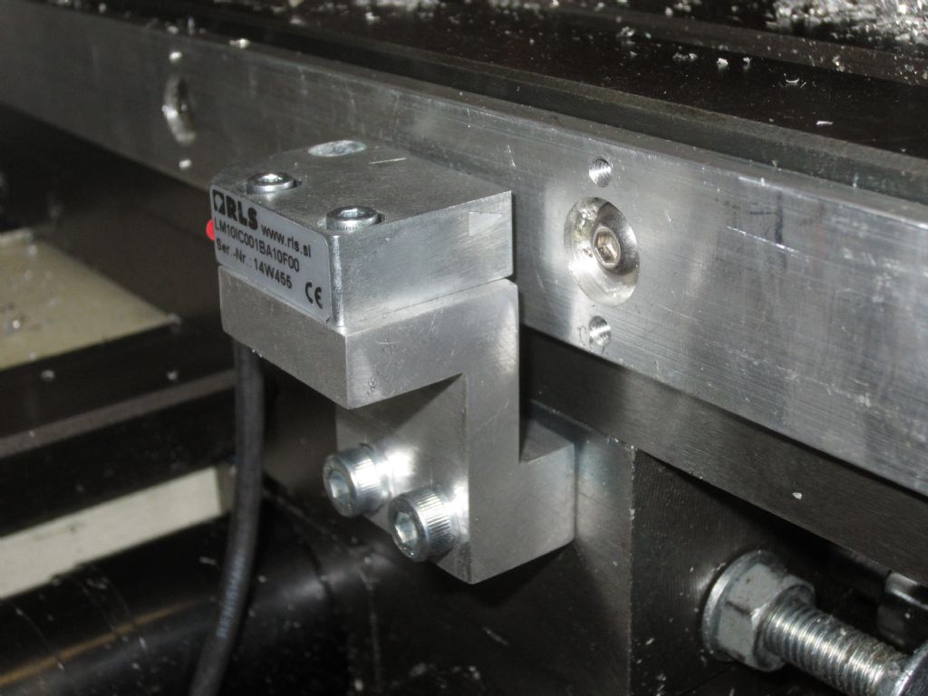
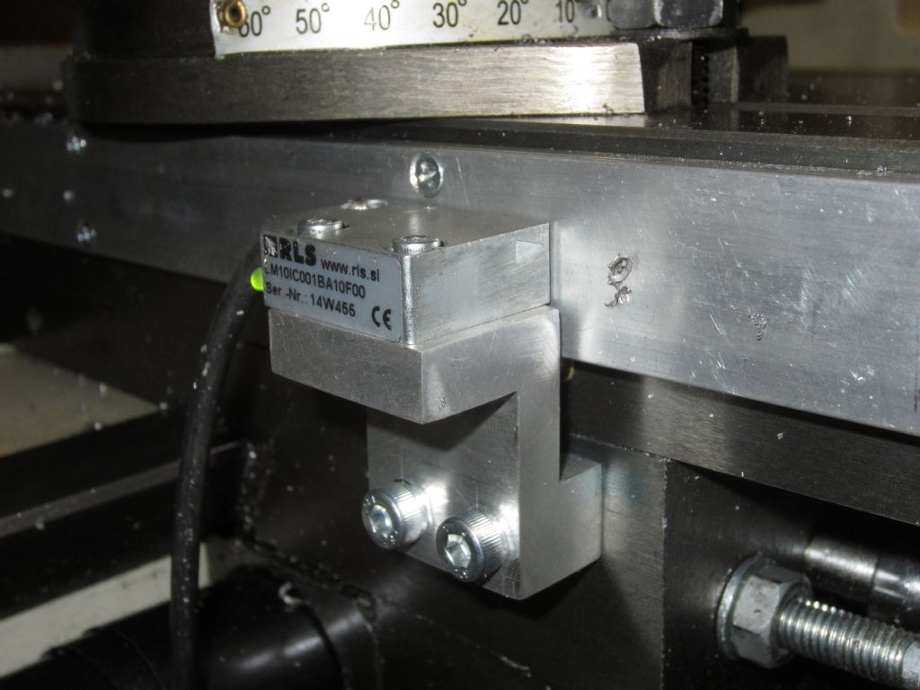
                                            I simply mounted the scale in a 2-part support profile (link in previous post). These consist of a bottom part with mounting holes that you screw to your machine and then stick the scale onto, and a top cover, that screws to the bottom part and completely covers the scale protecting it from swarf and coolant and being bashed. The readhead is perfectly capable of reading through the ally top cover with no affect on accuracy (ok, there is a tiny one, but being in the region on nm we can ignore this error source too!). The photo below shows the bottom part mounted, ready for the scale to be stuck to it and the top cover screwed on.

                                            img_0788.jpg

                                            The scale is magnetic and I guess, could get damaged by introducing foreign magnetic fields. However in practice you'd have to be trying pretty hard, i.e. by mounting a mag-base for a DTI right onto it, and even then you'd probably be ok. To give you some idea, I managed to put some scale in the same plastic carrier bag as a replacement motor for my lathe, and had no probs. The actual fields themselves are fairly small and don't radiate much above the surface of the scale so you'd basically have to place a strong magnet right up on the scale itself to damage it – and remember we've now got a cover on it so we've got an extra layer of protection.

                                            You're right, these are serious pieces of kit, and new they cost several hundreds of pounds. But they can be sourced much more cheaply on eBay and I'd much rather have a product designed precisely for this kind of application than one based on dismantled calipers or otherwise. That said, £300 was for me affordable, and for others it may not justify the cost.>>

                                            #103564
                                            Captain Biggles
                                            Participant
                                              @captainbiggles

                                              P.S. Other photos are available in my profile album thingy – called Encoder.

                                              If anyone has any questions I'm more than happy to help – DM me.

                                              #103630
                                              Captain Biggles
                                              Participant
                                                @captainbiggles

                                                img_0789.jpg

                                                I took a photo of the completed axis last night, for comparison to the last photo I put up. Note that the LED is now green, rather than red, showing signal strength & alignment etc are all correct and the encoder is working properly. You can also see how the top cover screws to the backing bar and seals the scale in place, protecting it from swarf & coolant etc.

                                                #103660
                                                Robin teslar
                                                Participant
                                                  @robinteslar

                                                  Smart work CB. Im amazed it works at such a distance from the strip. I thought it would have to be really close, 5 thou say

                                                  Robin

                                                  #103665
                                                  Captain Biggles
                                                  Participant
                                                    @captainbiggles

                                                    Robin,

                                                    That was shimmed up using nothing more than a business card – the beauty of these magnetic encoders (compared to the optical ones which are often so finicky that they have to have integral bearings and come as a complete module costing big £&pound that they have a really wide range of setup tolerances.

                                                    Rideheight (from the scale surface) can be anywhere between 0-1.5mm (compared to an optical which is, say, 0.8mm +/- 100um). Pitch, roll and yaw all have wide tolerances too, so all my holes on the mounting brackets were ovalised to give me maximum play, and the dead-easy-to-use set up LED simply turns green (from red) when everything is aligned.

                                                    More info on the readhead itself can be found here: **LINK**, the original manufacturer's page where datasheets and installation guides can be downloaded.

                                                    Under normal circumstances I would consider this sort of system to be beyond the budget of the standard home hobbyist, but with a readily available second-hand and v cheap source on eBay it all becomes worthy of serious consideration.

                                                    Joel

                                                  Viewing 24 posts - 26 through 49 (of 49 total)
                                                  • Please log in to reply to this topic. Registering is free and easy using the links on the menu at the top of this page.

                                                  Advert

                                                  Latest Replies

                                                  Viewing 25 topics - 1 through 25 (of 25 total)
                                                  Viewing 25 topics - 1 through 25 (of 25 total)

                                                  View full reply list.

                                                  Advert

                                                  Newsletter Sign-up