Dro, mains power adaptor.

Advert

Dro, mains power adaptor.

Home Forums Electronics in the Workshop Dro, mains power adaptor.

Viewing 19 posts - 1 through 19 (of 19 total)
  • Author
    Posts
  • #641242
    John MC
    Participant
      @johnmc39344

      I use several of these types of DRO in my workshop.

      screenshot 2023-04-14 at 10-43-04 accurate digital readout scale for milling lathe linear led dro 0-300mm ebay.jpg

      Powered by a either one or two 3volt button cells (CR2032). These batteries never seem to last long so was wondering if anyone has made them work from a suitable 240 volt to 3 volt mains adaptor.

      Anyone got any ideas for doing this?

      John

      Advert
      #32334
      John MC
      Participant
        @johnmc39344
        #641255
        Michael Gilligan
        Participant
          @michaelgilligan61133

          A Google search for

          cr2032 dummy

          returns a number of interesting avenues to explore.

          MichaelG.

          #641265
          John Haine
          Participant
            @johnhaine32865

            The ones that need 2 cells, are they in series or parallel?

            #641266
            Fulmen
            Participant
              @fulmen

              I suspect they would handle 5V just fine, making USB power a viable option. 3D printing a replacement battery lid shouldn't be too hard.

              #641268
              John Haine
              Participant
                @johnhaine32865

                Modern 3v logic families tend to smoke if supplied with 5v…

                #641272
                John Hinkley
                Participant
                  @johnhinkley26699

                  John MC,

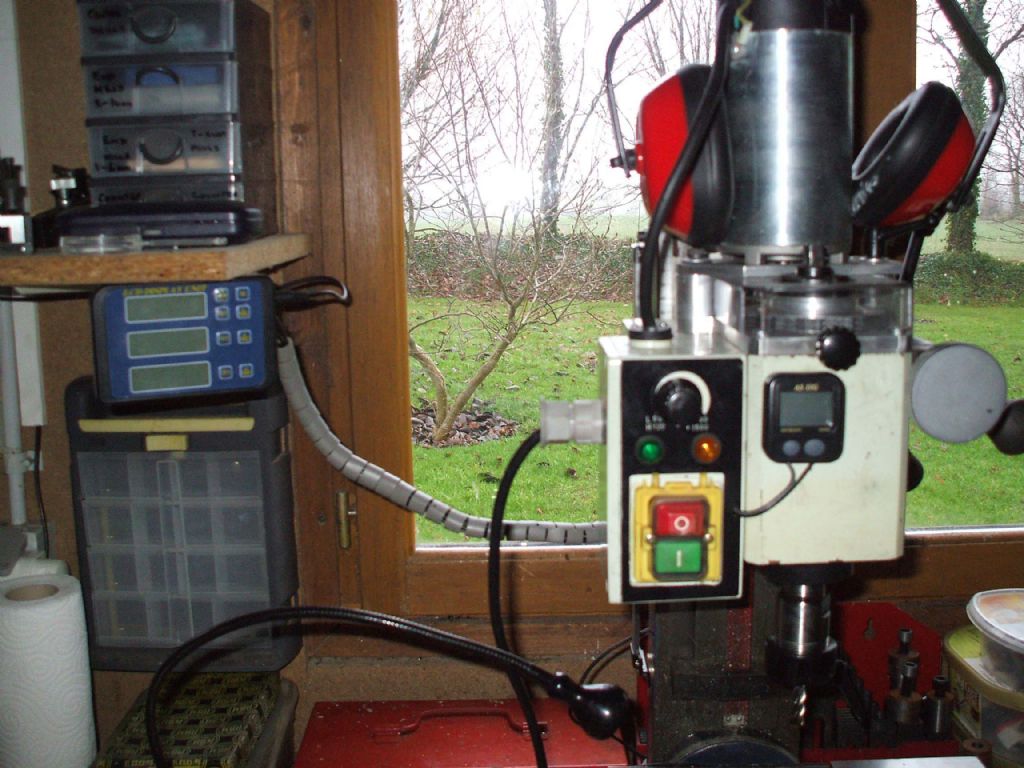
                  It is a good few years since I fitted my mini mill with 3-axis scales, obtained from ArcEuroTrade. Like you I found that the batteries didn't last long and I quickly replaced the supplied individual read out displays with a mains powered one similar to, if not identical to the one in the link above. I cannot say whether the voltage supplied to the read head is3V, 5V or 6V. The fact that it is supplied via a usb cable would suggest, to me, that it's 5V. An email to ARC would undoubtedly elicit a definitive answer. Not a cheap solution, but the saving in battery costs should be recouped within 8 to 10 years or so.

                  Remote readout

                  Not a brilliant photo, but it worked well enough within the limitations of the mill (and its operator). When we moved back to the UK in 2015, I sold the mill and scales etc to a friend nearby, to be replaced with a Warco VMC with glass scales soon after arrival in England.

                  Another alternative, I suppose is a Touchdro system from YurisToys of which I have read but have no experience I believe others on the forum have used this system however and if you happen to have an unused Android tablet lying around the place, could be a cost-effective solution.

                  John

                  #641277
                  SillyOldDuffer
                  Moderator
                    @sillyoldduffer
                    Posted by John Haine on 14/04/2023 13:39:26:

                    The ones that need 2 cells, are they in series or parallel?

                    I believe parallel, so 5V is over the top.

                    A while ago I experimented with a PSU powered digital caliper and found the electronics very vulnerable to electrical noise picked up by the power cable. The caliper had no decoupling, because it's not needed with a battery on very short leads Replacing the battery with a cabled PSU is complicated by the need to keep the power clean. A bit tricky because the caliper and John's DRO are both sensitive high-impedance devices.

                    I've toyed with the idea of simply connecting a bigger battery. If my caliper was typical, the reason CR2032 cells don't last long is because the circuit has a high voltage threshold and stops working long before the cell is fully discharged.

                    Dave

                    #641286
                    duncan webster 1
                    Participant
                      @duncanwebster1

                      When the spring better connector on my digital depth gauge broke I just soldered 2 short tails on and then attached an external AAA battery. Crude but effective.

                      #641289
                      Stuart Smith 5
                      Participant
                        @stuartsmith5

                        John MC

                        I have 3 of these fitted to my mill and found the display a bit small, so I made an interface box to use the scales with the TouchDRO app on a cheap android tablet. It uses an Arduino nano and a Bluetooth module.

                        810c920f-4359-4f62-93ca-7b0ce7ae70da.jpeg

                        The interface is powered by a 5v plug in psu via the micro usb socket on the Arduino nano.

                        This then provides power to the scales using the 3v output from the Arduino. Even though the connectors on the scales are micro usb types they are not 5v.


                        TouchDRO screen

                        This is picture of the TouchDRO app. This one is on my mini lathe.

                        Stuart

                        Edited By Stuart Smith 5 on 14/04/2023 16:58:49

                        Edited By Stuart Smith 5 on 14/04/2023 17:02:06

                        #641306
                        John Doe 2
                        Participant
                          @johndoe2

                          Slightly off topic, well parallel I suppose:

                          I got fed up with the short-lived button cells in my digital callipers, so I bought a mechanical dial calliper from Dasqua.

                          Now, my callipers always "switch on" and the battery is never flat, (there is no battery !). The mark one eyeball and 2 decimal places is more than enough for me – no precision metalwork involved.

                          The on/off switch of electronic devices uses battery power to sense the pushbutton switch, so it is always supplying current. It probably only draws nano amps for this, but that seems to be enough to shorten the battery life considerably.

                          I am surprised that nobody manufactures such things with a rechargeable battery and a mini USB connector.

                          Edited By John Doe 2 on 14/04/2023 19:07:43

                          #641310
                          Zan
                          Participant
                            @zan

                            1 get a battery box for rechargeable big celks at a much higher voltage than required I saw one at 3-35 v input

                            2 get a £3 variable voltage regulator from ebay set voltage to same as cells

                            3 fabricate dummy cell replacements to fit in the scale

                            4 fit in a case with an on off switch

                            job done

                            #641315
                            old mart
                            Participant
                              @oldmart

                              Some of these DRO's have a connection for an external power source, check and have a look at the instructions if there are any.

                              #641332
                              Paul Lousick
                              Participant
                                @paullousick59116

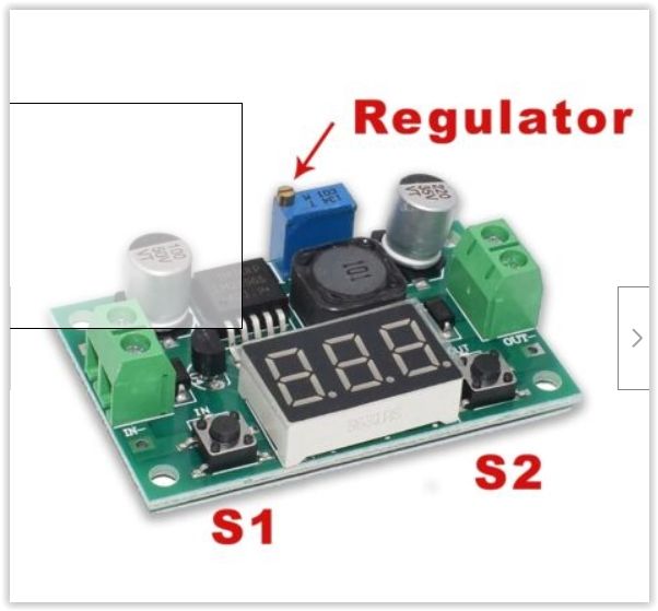
                                If your DRO only has a 3 volt supply, use a voltage converter (buck converter) to reduce the voltage.

                                Like this one that sells on ebay for £4.20 . Power supply can be any old DC phone/computer adaptor.

                                **LINK**

                                buck converter.jpg

                                #641366
                                John MC
                                Participant
                                  @johnmc39344

                                  Many thanks for the replies. I was hoping that I could use a 3 volt power supply, the sort that looks like a fat 13 amp plug. As has been suggested, the electrical output is noisy, the device won't like it. Also, my understanding of these PSU's is that they need to be made to "work". That is to say, the very low power demand of the DRO may not be controlled very well by the PSU.

                                  I wonder if using one of these powering a voltage controller may still have problems with electrical noise?

                                  At the moment I am favouring a larger battery to power the DRO. I'll need to make a dummy battery with flying leads.

                                  My last thought would be to use a mains USB adaptor connected to a voltage control device, (as in the previous post). Would this be electrically clean enough?

                                  #641387
                                  Michael Gilligan
                                  Participant
                                    @michaelgilligan61133

                                    John,

                                    Those buck converters are excellent for dimming LEDs and such, but they work by Pulse Width Modulation, so there is certainly some risk of introducing noise.

                                    You may, or may not, have problems

                                    MichaelG.

                                    .

                                    Ref. __ an extremely detailed data-sheet from TI here:

                                    https://www.ti.com/lit/ds/symlink/lm2596.pdf

                                    Edited By Michael Gilligan on 15/04/2023 18:29:56

                                    #641440
                                    SillyOldDuffer
                                    Moderator
                                      @sillyoldduffer
                                      Posted by John MC on 15/04/2023 15:48:42:…

                                      My last thought would be to use a mains USB adaptor connected to a voltage control device, (as in the previous post). Would this be electrically clean enough?


                                      Probably, except for the electrical noise picked up between the wall-wart and the DRO. The DRO expects a few clean DC microamps but what it gets is DC with a strong whiff of mains-hum, high frequency switch-mode spikes, and transients from motor brushes, VFDs, and other electrical clatter. Microamp level noise on the line is usually harmless because it's tiny compared with the hundreds of milliamps normally delivered into the load by the wall-wart, plus the load is decoupled to remove it.

                                      A DRO of this type is unlikely to have any decoupling because there's no long power lead acting as an antenna, and batteries don't add electrical noise.

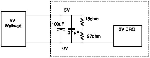
                                      I suggest a circuit that replaces the missing decoupling and reduces the relative level of unwanted noise by loading the wall-wart more heavily. Should also improve it's regulation.

                                      dropsu.jpg


                                      All the components inside the dashed box must be as close to the DRO terminals as possible. The wall-wart cable can be as long as is needed. Works thus:

                                      1. The 18 ohm and 27 ohm resistors together draw about 67mA from the wall-wart, giving it something to chew on.
                                      2. The resistors help limit any voltage spikes on the line
                                      3. The resistors are arranged as a potential divider, making 3V available to the DRO, which taps off the few microamps it needs. As its current requirement is small compared with what the resistors are guzzling, the supply should be 'stiff' – not changing when the DRO is operated.
                                      4. A 100uF capacitor is strapped across the line to short low frequency noise like 50Hz mains hum to ground.
                                      5. A 0.1uF capacitor is connected in parallel with the 100uF to short high frequency noise like switch-mode spikes to ground. It's needed because big capacitors react too slowly to short out fast changing voltages.

                                      Comment: 100uF and 0.1uF are typical values. I'd expect them to work, but de-noising can be a fiddly job. The optimum depends on whatever noise is actually present, so it may be necessary to experiment, or do the maths necessary to design a proper filter.

                                      Keeping it simple, if the DRO misbehaves, start by adding a 0.01uF capacitor directly across the battery terminals. If that doesn't tame the beast, try various substitutes for the 0.1uF between, say, 0.47uF and 0.047uF. Easier to do with an oscilloscope, but not every workshop has one!

                                      Dave


                                      Edited By SillyOldDuffer on 16/04/2023 09:16:38

                                      #641444
                                      john fletcher 1
                                      Participant
                                        @johnfletcher1

                                        Morning all, I notice DAVE above, suggest using a oscilloscope to locate electrical noise. I recently advertised a Farnell oscilloscope for sale in MEW magazine. John

                                        #641449
                                        not done it yet
                                        Participant
                                          @notdoneityet

                                          I am fairly confident that my 3 axis DRO readout can run from the mains, without any CR2032 cells in the readers. It is powered by a 6 volt 1 amp switched mode power supply, I believe.

                                          I believe that it is likely that you do not switch off the each reader when not in use? I expect that if you did, the cells would, in fact, last quite a lot longer.

                                          Likely a function of when it is off (really off) and not off (on stand-by🙂 ).

                                          This is mine: DIGITAL DISPLAY UNITS

                                          Edited By not done it yet on 16/04/2023 10:53:52

                                        Viewing 19 posts - 1 through 19 (of 19 total)
                                        • Please log in to reply to this topic. Registering is free and easy using the links on the menu at the top of this page.

                                        Advert

                                        Latest Replies

                                        Viewing 25 topics - 1 through 25 (of 25 total)
                                        Viewing 25 topics - 1 through 25 (of 25 total)

                                        View full reply list.

                                        Advert

                                        Newsletter Sign-up