DRO—-How accurate

Advert

DRO—-How accurate

Home Forums Beginners questions DRO—-How accurate

Viewing 22 posts - 26 through 47 (of 47 total)
  • Author
    Posts
  • #591394
    Martin Connelly
    Participant
      @martinconnelly55370

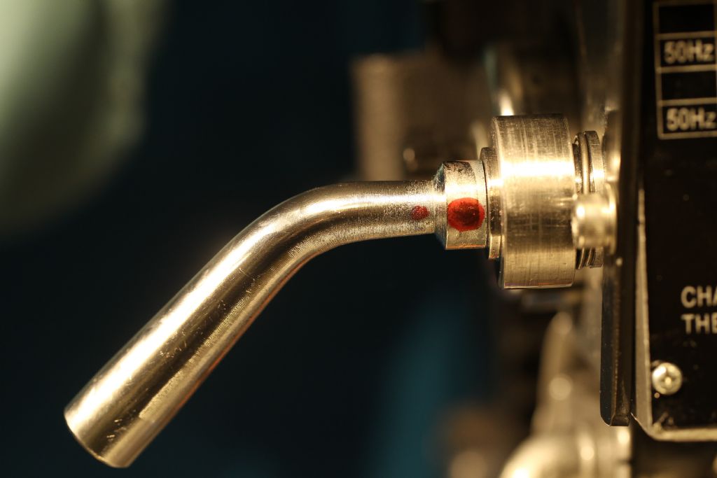
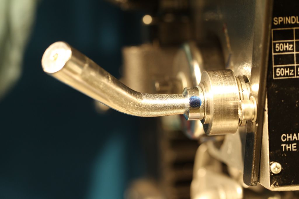
      I added some disc springs to my clamp lever.

      p1160273.jpg

      p1160274.jpg

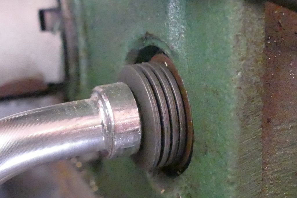
      These are 25×12.2×0.7 disc springs, 8 of them with alternating direction of their conical shape. The top picture shows the lever backed off and the bottom picture shows the normal position with the springs compressed to give a constant pressure and drag on the quill to give repeatable and predictable movement. I put the disc springs in the chuck on my lathe, held in the grooves in the standard jaws, to drill them out to 1/2" bore turning the chuck by hand. You can still clamp the quill up solidly when required.

      Martin C

      Advert
      #591400
      Hopper
      Participant
        @hopper
        Posted by Chris Mate on 24/03/2022 10:57:03:

        Ok, I took a test cut Aliminium bar:

        … etc …

        I think I am happy, let me know…My problem is the effort to get to that, this effort seems impractical and wrong to me.

        Yes you should not have to do all that pumping and locking and repeat. Best to check your bearings and the quill fit in the housing etc as Martin and Neil have suggested.

        I think most owners though do not use the quill feed to add depth of cut to milling. Instead they move the whole head up or down and keep the quill locked in one position. That way you put the DRO on the head and dovetailed column and eliminate the quill from the equation. The quill is used only for drilling and reaming holes etc.

        #591401
        Chris Mate
        Participant
          @chrismate31303

          Hi, thanks for the comments, got a lot of thinking to do.

          1) Regarding the problem I have, I am not sure if the Quil move seperate from the spindle, or if by locking the quil it amplifies a tiny bit wrong not clearly to be seen by my .01 indicators.

          2)-A complete another problem, it catch you unexpectedly, also the Fine Adjustment.

          Say I pump it in at the target I set, lock the quil finally at target, I then intentionally or accident touch & move the Fine Adjustment over its backlash, The quil just free falls down, now if the machine is running above a part with cutter, this can be a huge problem, so I am luckily aware of this now without crashing it into the workpiece.

          —I found if I do anything like slightly stiffening anything, the quil, or the Fine adjustment, I can fall into this trap, I feel I must feel the backlsh freely and clearly, iven if its a lot on the wormwheel.

          Note:THe Fine Adjust wormwheel the mating round part of which the worm turns into has dip machined into it, I suppose that is correct, it looks strange-?

          Edited By Chris Mate on 24/03/2022 11:39:42

          Edited By Chris Mate on 24/03/2022 11:40:19

          #591413
          Chris Mate
          Participant
            @chrismate31303

            From manual:
            z_quil fine feed worm gear.jpg

            #591415
            JasonB
            Moderator
              @jasonb

              I can understand some movement of the red DTI as the quill clamp is locked and unlocked and also some backlash in the quill rack.

              But don't see how you are getting different vertical readings for the spindle with the blue dti unless there is excess end float in the spindle.

              #591462
              Chris Mate
              Participant
                @chrismate31303

                My problem is all about locking the quil, to Mill by using the Fine Feed.

                Jason B, the blue indicator do not move if I lock the quil, this one is stable, however when actually milling, I of course cannot use this one, its in the way. "The spindle do not see the problem" If I could have tapped measurement the centre of the spindle, I would have had no problem.

                So I have to use the red indicator(From Quil)……I find a way around the problem.

                It works like this:
                To determine when the Red indicator can be trusted, I used both, and both move together, until I lock the quil then the Red one kicks off(My problem, now I am in the dark(Originally).

                -So when milling, I chose a setting on red one to aim for.
                -I then turn it to that measurement on indicator, ok, but as soon as I lock the Quil it kicks back like 0.5mm.
                -I now turn the fine feed again up to the setting aimed for, lock quil, it now kicks back 0.25mm.
                -I now repeat this process, it now kicks back only say 0.0125mm when Iock the quil.
                -I now repeat the process and turn the fine adjustment to the aimed setting, now it does not kick back anymore when I lock the quil.
                -Know I know it will mill to the setting I want and aimed for in a way thats accurate enough for me.

                My point is this cannot be right, so much effort.

                -I am looking for a selution before I will try to speak to the reseller, I 1st want to get all my ducks in a row understanding exactly what is happenning. At least I got a workaround now.

                Edited By Chris Mate on 24/03/2022 17:47:57

                #591516
                Chris Mate
                Participant
                  @chrismate31303

                  Today: I thought more about this now I have a work around established.

                  A]-If you play with the fine adjust wheel up and down without milling, I reach a pint where I wound up the "spongy backlash" out so it reach a point where as you go on from 0.1mm to 0.2mm to0.3 mm locking unlocking the quil in the process that you can go forwad with out the Red gauge deflecting…This is playing with it. The blue guage just confirm the spindle centre tip stay put at every stop. So removing the blue gauge is ok to go forther with the red guage.
                  -Now however if you actually mill, you cannot just wind on through the part you milling, you mill in small steps.
                  Because of this everytime after a milling, when you adjust it down a bit for next mill, that spongy backlash is back all over. This is where I use my workaround as descibed before.

                  B]-Today: I decided to look at the Handwheel-Wormgear design, the quil + spring + its backlash is one thing, what happens here is another. I completely forgot about this spring.
                  -THe workwheel assembly in housing is solid no play in this desgn with two bearings.
                  -I decided to look at this backlash…It feels huge turning the knob, but according to the non adjustable scale on it, it has backlash of 0.7mm……Then I ralise this is roughly the 1st needle deflection I saw when locking the quil, and as I repaet that process described before this get less and less at the red guage while I know the spindle stasy put. So something weird is going on in this arena, my thoughts.

                  C)-So today I am going to look at the SPRING fitted to the knob on drilling handle you wind down in to enguage the Fine Feed handle and wormwheel. I know the quil with its spring press against the wormgear, I can hear it, it sounds like tacky grease making contact in this assembly.

                  -I am going to remove the spring.
                  -I am going to replace the spring with same lenght bushes and shorter bushes to mimick the spring compression if needed.

                  -I am not sure where this is going to lead, but I think its an area worth exploring.

                  #591530
                  Nick Wheeler
                  Participant
                    @nickwheeler

                    These posts contain lots of words.

                    But no parts, which is the reason most of us have machines.

                    How do the parts measure, compared to what the drawing states?

                    #591556
                    martin haysom
                    Participant
                      @martinhaysom48469

                      at the risk of upsetting a lot of people on here

                      we buy a budget machine put it in a shed then try measuring to .001 with something marked to.01that we have had for years. i think its too much to ask for. perhaps better to say can i make stuff does it work if yes no problem. however if no and .001 mm limits are really needed its time to spend some very large sums of money

                      the machine shop where i work, works to these limits – million pound machines – tempture controlled workshop – measuring equipment sent away annually to be checked.

                      moan over i off to the shed my cheepo Eastern mill and my 80 year old English lath is waiting

                      #591725
                      Chris Mate
                      Participant
                        @chrismate31303

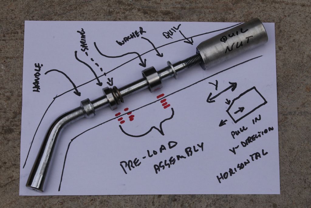
                        Ok, I keep it short, after two days of looking into the Drill handle-Microfeed setup & Quil Lock I have repeatble success. I end up back at the Quil Lock mechanism and thanks Martin Connelly for your photos, I arrived at a selution with what I had today had on hand.

                        A-I removed Quil Lock assembly complete, Handle + Rear angle faced part to match the quil facing part inside head. So I found dirt & paint blops o this part. I cleaned this area thoroughly.

                        B-I then look at the preload idea.

                        -I added two washers with in between them a water tap rubber washer and two smaller washers on the end. I the cut a washer 3/4 thickness of tap rubber and a hole to house the tap rubber(stiff).

                        -Assemblyp: Handle…..small washer….Large washer…..-Large thicker washer bored out to house water tap rubber-….Large washer…Small washer(To take up gap between casing & hole to tighten Quil Lock aganst.

                        -I found an easy spot to point the handle(Repeatable as well-Pints to end of electrical box casing front), preload in action now….., I then dial in the guage to depth, lock quil and needle does not move….I repeatedly did this without mill running, and with mill running the needle do not move when locking all you see is a little vibration from mill running(repeatedly).

                        So Martin Connelly your idea works, I just did it with different components……At least after all this crap I know the mill better. (In this whole process the fine adjust backlash decreased from 0.7mm to 0.35mm, not sure why).

                        #591910
                        Y C Lui
                        Participant
                          @yclui16187

                          On my Emco FB2 mill, the quill/spindle would tilt and shift in Y position when the quill handle is pressed. I attribute this to the imperfect fit between the head and the quill. I think your obseration on the difference in the two dial indicator readings can be explained by the tilting change of the quill/spindle when the quill is locked / unlocked.

                          On my mill I always lock the quill when milling, edge finding and adjusting the tram so this is the reference position of the quill. When drilling, the quill need be unlocked and the Y reading of the DRO need be corrected by 0.11 mm in order to get the spindle to the correct position. There is no ways to compensate for the tilting of the spindle but the error is acceptable to me as most of the holes are for accomodating bolts and high precision is not required.

                          Edited By Y C Lui on 29/03/2022 11:34:29

                          #591988
                          Chris Mate
                          Participant
                            @chrismate31303

                            YC Lui, I understand what you saying, my problem is how the guage I am using to go down step by step as I mill.
                            Due to the problem you mention, I could not trust my guage, and my question was how accurate due to this would a DRO be…. I prefer the guage(Dial Indictor) knowing this now, because its very easy to observe a needle swinging rather han a DRO given numbers that jumps up or down and I have keep on computing that in my head.

                            Even without the selution the dial indicator will be an uneccassary effort to keep track at wich dept you were and where you aiming for.

                            Now with the selution what I see on the dial indicator after locking the quil is the same as before locking the quil is the same as which nect depth of cut I adjusted it to, so I go forward straight forward.

                            Think about it like this:Before the selution, if you advance the quil down say0.01mm then the dial indicator does indicate that, now you lock the quil your indicator jumos 0.05mm. Because of this it mess with your head as you going forward.

                            I know have a selution that workd for me with the tap washer, I am going to try to improve on thsat by maching two round pieces with a spring in the one to compress for preload, like the washer. The spring will be longer laster.

                            Note: The ideal in this Quil-Spindle-Fine adjust engineering would have been such that wherever you lock the quil down that is the position it sit before the pockdown, so it does not move. I can probably make a contraption doing this, but not at this stage with what I got. I have to plow in more money for cutters and MT Collet holders and collets, just face milling at the moment to sort out some problems I can eliminate.

                            Note:If you mishandle the preload(too stiff), or lock the quil, then touch and turn the fine adjust, you are presented with a complete new problem if the quil is unlock…Now it jumps to who kmows where, so once you started milling down in steps, you must not loose track of the backlash in the fine adjust wormwheel.
                            Play with tis and you see what I mean…Now with the selution you can take it back to where you came from by using the preload.

                            Note:I did look at my mill heastock adjustment with crank handle and will fit a DRO to the vertical ways, this will be no problem. Actually it does go down easily and smoothly and thats the direction I am milling in any case, its just as it is more cumbersome to use as the fine adjustment, unless I modify it, using a 90 degree small gearbocx and with steering universal joints bring it forward beneath the left side of the bed with a proper handwheel to adjust.(I will probably do this).

                            #592001
                            Y C Lui
                            Participant
                              @yclui16187

                              Chris, My machine is simpler than yours, I don't have any fine adjustment mechanism on the head. The quill can only be moved by operating the quill handle. To change the Z value, I just move the entire head and then lock it before cutting. However, the DRO reading still changes by 0.01 ~ 0.015 mm due to locking / unlocking of the head but the change is quite consistent so I just add that amount to the Z reading before locking. For example, if my target Z value is 30.000, I will move the head until the DRO reads 29.990, then lock the head, the reading will jump to 30.000 ~ 30.005. There can still be an error of 0.005 mm but I just accept it in most cases. If I really want to eliminate that tiny error, I will just try again and lock the head at 29.985.

                              Not sure if this "software compensation" ( runs in the brain ) is applicable to your machine though.

                              Edited By Y C Lui on 30/03/2022 00:06:28

                              #592004
                              Y C Lui
                              Participant
                                @yclui16187

                                Another thing worth exploring is whether the tilting of the quill/spindle in the unlocked state is always in the same direction. All measurements have indicated that mine only tilts along the Y direction. I believe that's because the gear mechanism driving the quill up and down is at the "north" side of the quill. If this is the case in your machine, there should be a location along the edge of the quill where the Z reading change is always the same as that at the center of the spindle. If such location can be found, linking the DRO head to that point should solve the problem.


                                Edited By Y C Lui on 30/03/2022 00:18:32

                                #592009
                                Chris Mate
                                Participant
                                  @chrismate31303

                                  YC Lui, remove your quil lock handle , then go to otherside and remove the round nut, it has an angled face as well as the opposing part of the quil, so it will try to lock in the Y- direction without the nut turning, see if you agree-?

                                  #592173
                                  Chris Mate
                                  Participant
                                    @chrismate31303

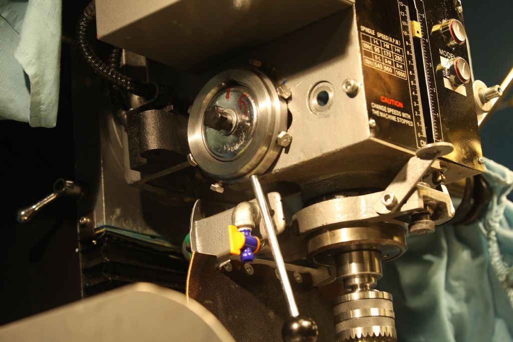
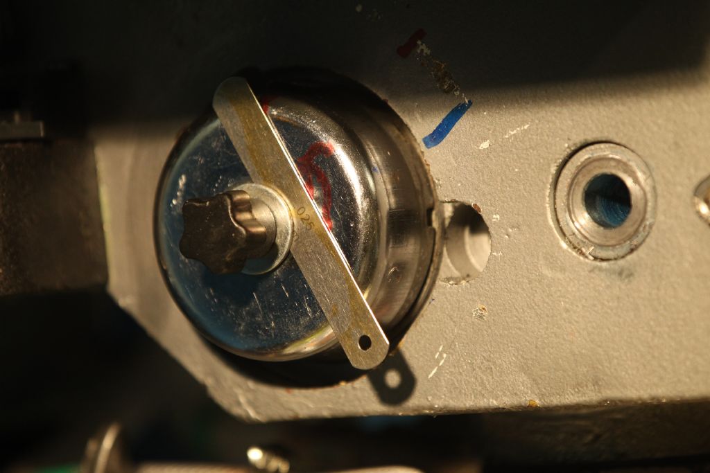
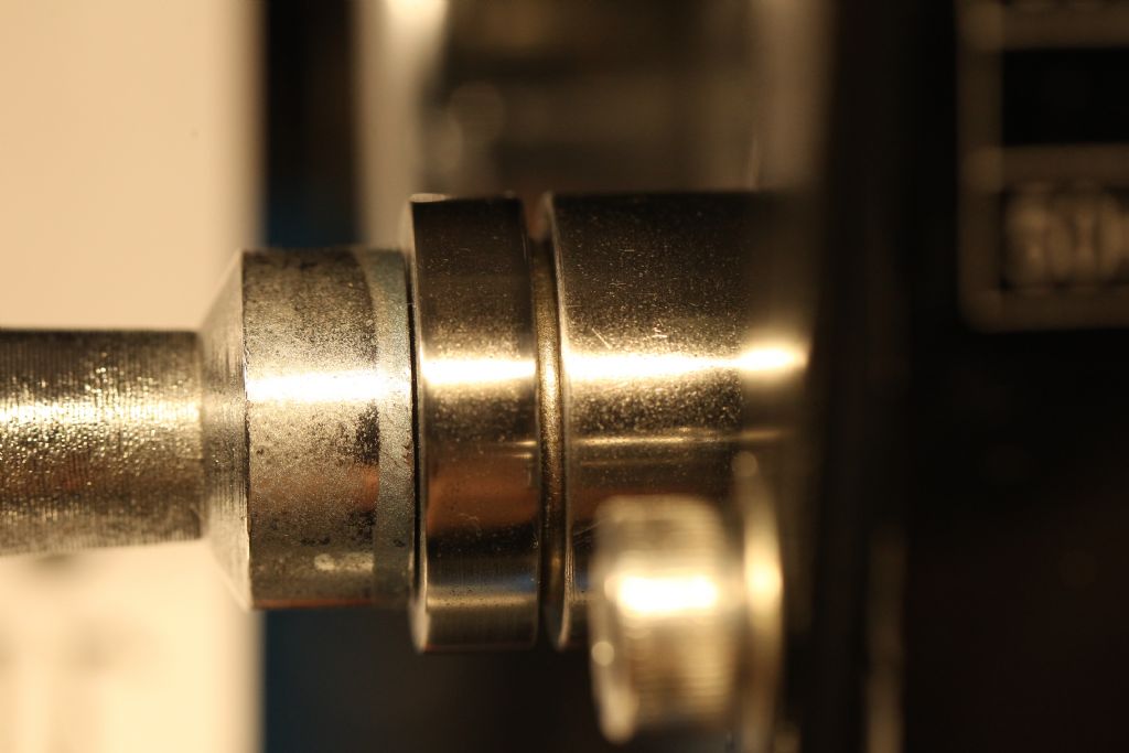
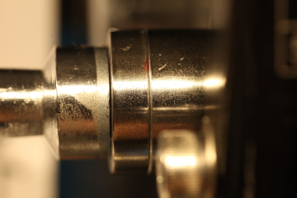
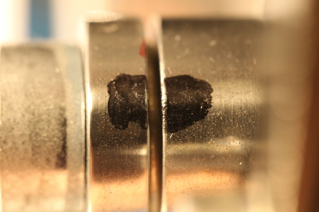
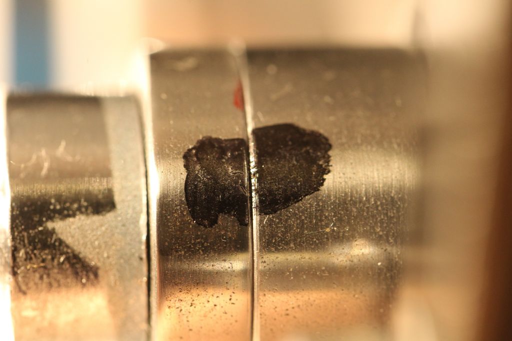
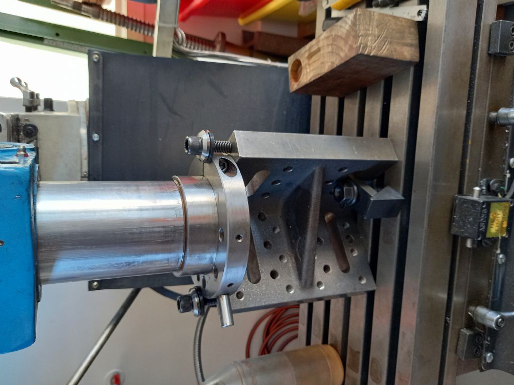
                                    I added photos to explain some parts made & used:

                                    1-I added positive tention to quil spring, made tool.
                                      -I prevent quil spring cap being jammed by tightning bolt.

                                    2-I added preload before quil lock to prevent dial indicator give false readings.

                                    3-I am now happy with this on my mill.

                                    01_quilspringadjuster-paint.jpg


                                    02_quilspringadjustgap_paint.jpg


                                    03a_quillockpreloadassembly_paint.jpg


                                    03b_quillockpreloadassembled_paint.jpg


                                    04a_preloadassemblygap_paint.jpg


                                    04b_preloadassemblynogap_paint.jpg


                                    05a_preloadassemblygap2_paint.jpg


                                    05b_preloadassemblynogap2_paint.jpg

                                    Edited By Chris Mate on 31/03/2022 10:12:05

                                    #592275
                                    Jon
                                    Participant
                                      @jon

                                      Same Lux head as mine but my quill casting wore 14 years ago oval. Last time measured was around 0.6mm. I drilled and tapped M5 round the lower casting to put pressure on quill in desired direction. The lock pushes quill rearwards.

                                      Seen and proved loads of errors on others caused by using the depth stop to move any scale, theres always play but its very easy to do that way.

                                      #592737
                                      Chris Mate
                                      Participant
                                        @chrismate31303

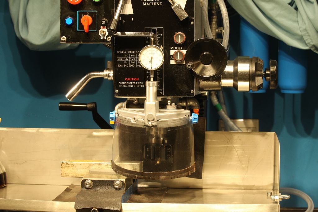
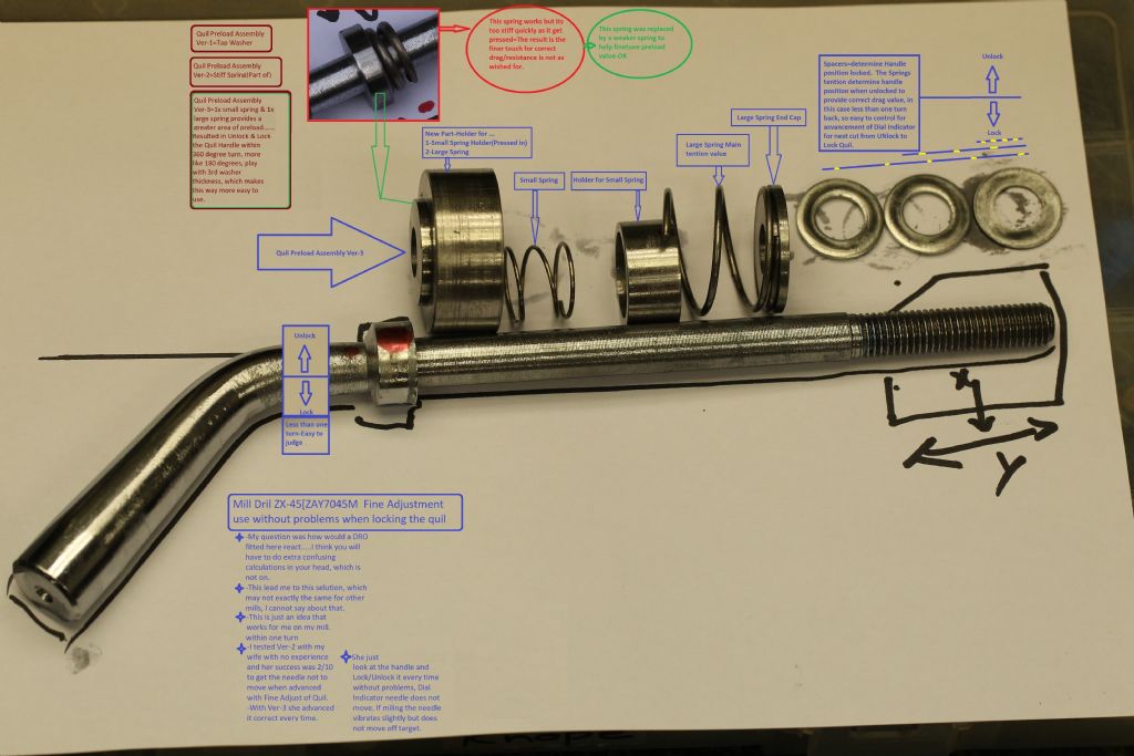
                                        Mill Drill Quil Lock used with Fine Adjust provided on ZX-45[ZAY7045M] mill(New).

                                        When Quil is locked the Dial Indicator needle deflects, a DRO here would probably not work well as a result.

                                        Ver-1=A tap washer was used…..It worked but….

                                        Ver-2=A stiff spring was used, but after I tested it with my wife with no mechanical experience, she was only 2/10 times successfull advancing the quil down 0.1mm without deflecting needle. I then realise the stiff spring was giving a too narrow band of tention to judge the drag applied before Locking the Quil without understanding how it works.

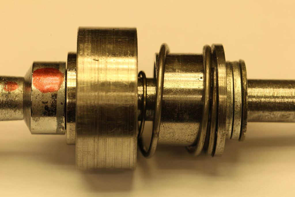
                                        Ver-3=So I relook the effort and decided to use two weaker springs which gave a much wider flatter tention range that was enough before Locking the Quil and I could Lock/Unlock with the handle with in one turn, within 380 degrees, so now you look at the handle position, and you know instantly where Lock & Unlock position is.
                                        The 3x washers can be played around for 1-Needed gap, 2-For determining the Quil Lock position.
                                        My wife could repeat every time with this effort without the needle moving after Lock applied.

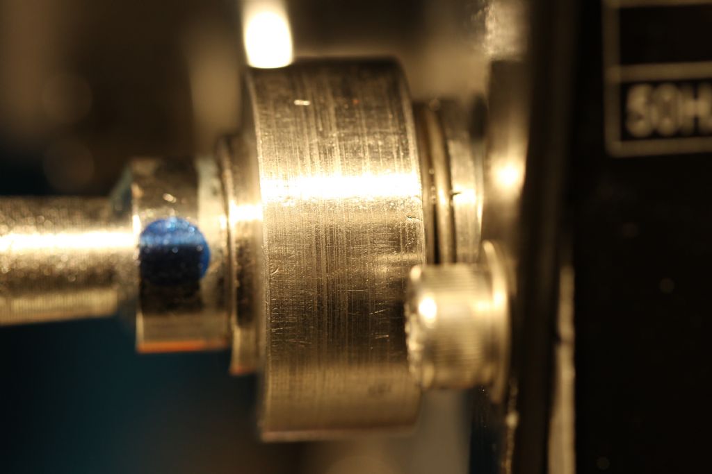
                                        So here are the pictures for those that might be interested:

                                        01a_preloadassembly-parts ver3-paint.jpg

                                        02_preloadassembly-assembled-paint.jpg

                                        03_preloadassembly-installed-locked-paint.jpg

                                        03a_preloadassembly-unlocked-paint.jpg

                                        03b_preloadassembly-locked-paint.jpg

                                        #592785
                                        Neil Lickfold
                                        Participant
                                          @neillickfold44316

                                          Chris, On my HM50 I have found a lot of issues, only from this thread and ideas posted. In my case, when the quill was down, it's total movement was 0.18mm , so basically impossible to do much. I did get the spindle housing, flash hard chrome plated, and test fitted it. It was chromed slightly more than expected, so I borrowed a hone and found the housing was both out of round and out of alignment. Hindsight, I should have taken the housing to an automotive place and got them to hone and align it to the back face, then chrome the outside and have it ground to suite. I digress. Then I put in the new bearings but they seemed to not feel right. Took it all apart and found that the Bottom bearing seat face was not inline with the housing. Corrected this by using a bigger lathe and a steady rest to just recut and clean up that face. The bearings and the housing feel good. I also discovered that the spindle top bearing shaft diameter was made 0.015 or so over sized to suit the bore of the top(No name) bearing that they used, and that needed to be corrected before fitting the new (Branded bearing). Now the quill is a little on the tight side, but at the moment is really good. My next step is to get some parts cast up, so that I can have the type of quill lock similar to the one in the video by Stefan Gotteswinter . My thinking is to do this upgrade now while the process of sorting out the machine. It will limit the stroke by about 18mm or so, but I think the better quill locking abilities are worth it. An upgrade is that I will be using a replaceable piece of bronze bearing material in the locking bracket instead of just the cast iron. That way when it wears out, a replaceable part can be inserted instead of doing the repair stage latter. Currently with the drag of the quill to the housing I can engage the fine feed down and it works well with good control for the time being. My ZX45 will get the upgrades as I have done with this HM50 mill, except I will get the housing honed first, then get the quill body built back up again.

                                          20220331_174626.jpg

                                          #592795
                                          Chris Mate
                                          Participant
                                            @chrismate31303

                                            Hi, Niel Lickfold……….I accept that my mill is not perfect and a drillpress with a X/Y bed fitted at best.

                                            As far as I can see its not that if my mill bearings are ball bearings(I was told it had taper roller bearings, however the bogus manual with it says ball bearings. I think for what I got, I am happy to get a way around the problem messing with the Dial Indicator when I lock the quil, actually at .01 I cannot see movement at the tip of the spindle when this is happenning with a .01 Test Dial Indicator, however I accept if I use a .001 Test dial indicator I might very well see something. I think whatever there is, the way the quil function at best up & down in a sleave situation, it amplifies the further from the centre you mount your indicator for use to see where you going by using the fine adjust, of course you cannot monitor the centre of the spindle because its turning.

                                            Ignore bearing problems for this argument, those can be considered "faults", however the Quil/Spindle relationship might be just an engineering crossroads.
                                            I see it this way, and mabe wrong here: A Lathe's spindle does not have this type of a problem, because it does not have a quil, or any other spindle that does not have a quil its permanently locked. My point is with the quil at best, it will show some deflection because you monitor the quil and not the spindle, and a quil moving up and down, cannot ever be better as the best bearings made.

                                            My question is do you think if the quil is as good as it can get("Perfect&quot, you will have/can have zero deflection if you lock it-? I am trying to seperate an engineering issue due to desighn from faults.

                                            #592800
                                            Neil Lickfold
                                            Participant
                                              @neillickfold44316

                                              My quill had engineering issues, but the bearing diameters in the quill were within 0.01mm of concentricity. So I found that the housing that the quill runs in had in my case miss alignment problems too, that just amplified when the quill was extended. Since the chroming etc it is really good. Within 0.02mm over 127mm stroke. It is about as good as can be expected with these type of machines. The cast iron used is not a rigid or as a high a grade or quality as used in the good machines. Trying to get the quill to run true with vertical element is not all that easy. You need something to test the squareness of the table to the back column. It may be that you need to shim under the column base to get it square in both directions, left /right/ then vertical. I used an angle plate that was made to better than 0.003mm over its length. Cylindrical or bottle squares are also very helpful. But without any master reference it is very difficult to tell just where all the errors are and what will need correcting. I don't think that a ball bearing or a taper roller bearing is really going to make any significant difference to a spindle on a hobby machine with the small powered motors of under 2.2kw, 3hp.

                                              As for the locking side, the add on locking like Stefan has done I think is a better way to lock the quill. Another way, but mine does not have the extra material below the casting like Stefan has, but my ZX 45 has a lot of issues that needs to be sorted out. The 1st issue in mine is the casting is bored too much oversized for the spindle. So if it has around 0.06mm clearance in the bore, fixing just the bottom is not going to fix the loose top that then allows the spindle to pivot or rock in which ever direction that it wants to.

                                              On my ZX45 , I have already taken apart the table fixed some of the tables manufacturing problems, and added an oiler system from a single point. I now have the spindle and the gear box to work on, then no doubt it will then finally be the fitting of the column to the main base and shims, along with the gibs and the main block assembly. I am sure most of it has a lot of engineering issues.

                                              Over all, these machines are really quite poorly made and clearly no time or checks happen during their production. So if you really want it right, you will need to spend quite a lot of money correcting the engineering on it. I think it will be around nzd $800 to fix the spindle and the main casting bolt on piece. That covers the honing time and the chroming. I will need to do the grinding of the quill and the other work. The other option seems to be spending a lot more money and be buying a machine with a head that can pivot in 2 directions like the Bridgeport or Kondia mills have. But they are around 3x the price and often are too high for the average garage to have it in place.

                                              I too will be looking for the ways that people went about fixing these sort of machines and see what the outcomes are. I hope this helps some what.

                                              Neil

                                              Edited By Neil Lickfold on 04/04/2022 02:20:59

                                              #592802
                                              Y C Lui
                                              Participant
                                                @yclui16187
                                                Posted by Chris Mate on 30/03/2022 05:42:20:

                                                YC Lui, remove your quil lock handle , then go to otherside and remove the round nut, it has an angled face as well as the opposing part of the quil, so it will try to lock in the Y- direction without the nut turning, see if you agree-?

                                                The construction of the quill lock on my mill is not like that. The locking screw squeezes down a slot cut in the wall of the bore to reduce it's diameter and grab the quill more tightly. The method you have described is used on the quill of my lathe's tail stock. 

                                                If the concern is just getting an accurate Z reading on the DRO, it will be sufficient to find a point on the quill where the vertical position is unaffected by locking. I will show what I mean with a video when I have time.

                                                Edited By Y C Lui on 04/04/2022 04:18:37

                                              Viewing 22 posts - 26 through 47 (of 47 total)
                                              • Please log in to reply to this topic. Registering is free and easy using the links on the menu at the top of this page.

                                              Advert

                                              Latest Replies

                                              Home Forums Beginners questions Topics

                                              Viewing 25 topics - 1 through 25 (of 25 total)
                                              Viewing 25 topics - 1 through 25 (of 25 total)

                                              View full reply list.

                                              Advert

                                              Newsletter Sign-up