I have an Amadeal AMAT 210V mini lathe 8″ x 16″ and I am looking for a 2 axis DRO which uses ‘slim linear scales’ but ideally has a nice big bright readout.
I bought the lathe used and it came with ‘slim scales’ fitted which have micro USB connectors on the ends of the cables which fit to small individual LCD readouts (the read out seems quite popular and looks a bit like small temperature readout/timer module etc) The issue is that the scale cabling has become damaged (it wasn’t well protected) and I find the read outs not great to read so in replacing this I would like a bigger display, but due to the size of the lathe I think it would be good/essential to keep the linear scales the same slim profile.
I have recently fitted a decent enough 3 axis DRO set up to my Seig SX2 Mini mill and whilst the shrouded linear scales fit, they are a bit clunky for the small machine. I have held the same scales up against my lathe and I cannot see how these units would fit my cross slide without causing significant obstruction.
I am struggling to find a suitable device to fit my lathe, I guess that lots of people have fitted DROs to their mini lathes, I would be grateful for your advice.
Think about magnetic scales, you might even be able to stick the magnetic tape onto the existing bars, small read heads are smaller than what it sounds like you already have and they plug into the proper big DRO consoles with all the bells and whistles
Thank you @JasonB this looks like what I need. I can see that the separate sensors have ‘D’ connectors for connection to the larger display units, so that ‘s ‘a tick’, although I am unsure how the sensor tape is applied.
Given that my current sensors are magnetic I assume that I cannot just apply the new tape to the old strip, they would interfere I guess.
Also I have just noticed that buying all of the bits separately like this makes it quite a bit more expensive :0(
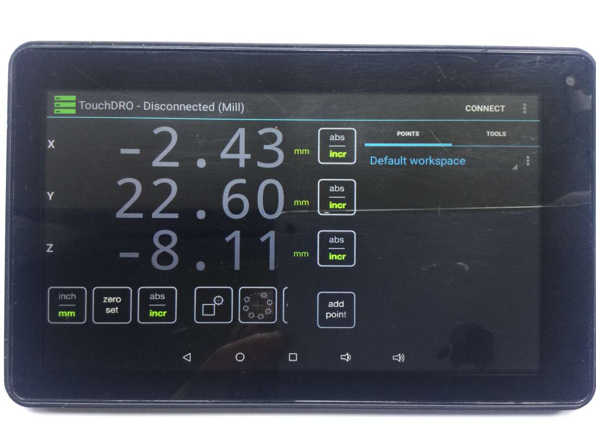
I fitted these to my mill but found the display a bit small. I made an interface circuit with an Arduino and Bluetooth module and use this with an Android tablet running the ‘TouchDRO’ app which is a free download. This photo shows the display for a mill, but you select a lathe option which gives the normal sort of functions you get with an expensive DRO.
I have used the magnetic scales and heads from Machine-DRO with the Yuriystoys Touch-DRO software. The ones I use have fitted on a small Cowells ME90 lathe and also the Cowells Milling Machine. The newer readheads are even smaller than those I used.
Thank you @stuartsmith5 my current slim scales are just like those you picture. I had not heard of the app, that’s very interesting nice display, thank you for the idea.
My search for a suitable DRO to fit my 8″ x 16″ mini lathe is still proving to be a challenge.
I really like the one I fitted to my mini mill last year, I use it a lot and have come to trust it implicitly, it came via Amazon and no doubt come from the same factory as many of these low cost devices.
I would be happy to buy the same again, but I need it to have a slimmer scale for the Y-axis because the only viable place to put it is on the chuck side of the carriage and room is in short supply.
Have any of you managed to solve this puzzle, I’m getting a little disillusioned with my fruitless search and may be tempted to buy a more expensive scale if need be but given that the lathe was a low cost secondhand purchase I’m not thrilled at spending double the cost of the lathe on the DRO!
I did check out Yuristoys DRO, but I would be more comfortable with a purpose built solution.
I don’t have a solution I’m afraid but <PEDANT ALERT!> if you mean a scale for the cross-slide then by convention that is usually labelled “X”, and the longitudinal axis “Z”.
I see what you are saying John, in my current arrangement, (I have a pair of cheap magnetic scales attached to what look like LCD kitchen timers!) the scale that rides on the carriage and that gets close to the chuck measures the ‘Y’ movement the one that measures the movement of the carriage in the ‘X’ plane sits behind the length of the bed and I could get away with a bulkier scale here.
I’ve always taken the ‘Z’ plane as vertically up and down. I guess it doesn’t matter as long as the person reading the scales understands what they are measuring :0)
My reason for changing this is that the long scale occasionally jumps, usually it jumps a lot and I notice and go back and set my datum again, but its a worry once you start to trust these devices. Otherwise I would be happy to stick with the low cost solution. I do like the bolt hole array function on the mill though.
The XYZ definitions come from a mill. Imagine a mill turned on its left side so the Z axis becomes horizontal. Then the X axis is “in and out” and the Y axis unused (except in some specialist machines).
Hello again, I’m in the process of fitting my DRO to my mini lathe, it replaces two separate digital displays which due to their simplicity really benefited from being mounted on the back wall of my workshop on a wedge of wood limiting their mounting position to just above the back splash guard behind the carriage.
I notice that many people seem to position their display behind the headstock, so I am guessing that this is ergonomically the right place, but I am unsure about reaching across to the left with my right arm.
What do you think?
Sorry to be a wet blanket, but is it worth the bother of fitting a DRO to a lathe at all? Whilst hugely beneficial on a milling machine, they don’t add much value to a lathe.
I’ve not done a comprehensive study of where lathe owners put their DROs, but my impression is that they’re mostly mounted on the headstock, or on the back panel just to the right of the operator when the saddle is close to the chuck, and rarely on the saddle.
Where the DRO is positioned may be as much to do with installation practicalities as ergonomics. The saddle is best ergonomically, because then the DRO and cutter are close and move together. Unfortunately, saddle mounting is the most awkward installation and the display is likely to get in the way. Fitting to the headstock is a good compromise – plenty of room for wiring etc, plus the display and chuck can both be in the same eye line. Undermined by most of us being right-handed, making access to the controls awkward. The back panel position solves the control position problem, but the display is no longer a glance away from the cutter. May not matter!
I suggest that a DRO fitted lathe is used in three modes:
‘set-up’, in which the DRO is used to adjust a cut by a known distance. (A job that dials do equally well unless the screw is worn)
‘normal’, in which the machinist concentrates on what the cutter is doing, and rarely looks at the DRO
‘instrument flying’, in which the machinist trusts the DRO read-out and doesn’t eyeball the cutter.
CNC machines are the ultimate in ‘instrument flying’, and their controllers are positioned in all manner of places. This early example shows the ‘DRO’ and operator several feet away from the machine, and some modern installations put the control panel so the operation stands with his back to the machine. I guess this is done to stop unskilled machine minders trying to fix stoppages: it forces them to send for an expert!
I would agree with your comment re DRO’s on a small lathe vs a milling machine where i have found it very useful. However i have had the benefit of using a very basic one on my lathe, basically a pair of independent scales each attached to small LCD displays which look like kitchen timers! and I have found them very useful especially when making lots of the same thing.
In my old situation the displays were located slighty above and behind the cutter and to some extent I have got used to machining by reading the instruments, unnerving at first but once I started to trust the readouts a whole world of pain, (backlash) largely disappeared. I quite like this.
I do know that I have to avoid the area in front of the ‘black oil stripe’ up the wall!
I can see how mounting off the back of the carriage would be effective, the readout always being just a glance away from the workface. Perhaps mounting above and behind the splash back ‘tray’ would be the closest I can get to this.
Big long bed lathes tend to mount it on the carriage as they may be doing work a couple of meters from the headstock and then the next job may be close to the chuck so things need to be where the operator is.
Our small machines can really go where you like as they will be in reach and visible with a turn of the head. Does not matter too much about looking at both chuck and readout. I don’t look at the cutter or handwheels when winding the mill to a DRO reading.
Safety suggests right hand use of a headstock mounted readout is not ideal but if you use your left hand for starting and stopping the lathe and altering the speed you should also be able to work the DRO with your left hand. Right hand end is safer and if it is where you are used to looking then I can’t see a problem with that.
If your console came with a wall mounting bracket then that should allow some movement from tailstock to mid position all of which can be worked with the right hand and is probably where I would mount one as my mill DRO is to the right.
As a possible sign off to my original post I wanted to mention the solution to my challenge.
I cobbled together a set of parts including an LCD display from Sino and optical scales which would work with it and which are fitted with the industry ‘standard’? D-type plug. I have a Mill with a traditional green LED 7 segment display and find the new black text on white background LCD screen clearer to my eyes, in the bright lights of my shed/workshop.
Selecting a suitable scale for measuring the movement along the line of the bed wasn’t too much of a problem as there is more room down the back of the lathe, I chose the Sino KA500, but during my search I happened along a small optical scale from Sino the KA200, the main body of the scale is 16mm x 16mm which makes mounting it across my lathe a lost easier avoiding too much obstruction with other stuff. It is less robust looking than the bigger scales but so far it seems OK.
Dave, where did your fine photograph come from? The job, ghosted or clear plastic, looks as if it is a casing from a jet engine. When I was an apprentice in the late 1960s the experiental machining shop at RR Derby had a few similar (I think) machines on trial. They were viewed with a mixture of curiosity and wonder.
Touch DRO on a Android tablet works well. It uses Bluetooth and so you can put the tablet anywhere and you can buy an interface to connect the scales into to supply blutooth connection. The system is easily set up for scale direction and number of scales etc.
I also use I-Gaging scales connected to a Blu-DRO bluetooth interface and 7″ Android tablets on both of my mills. Works extremely well and has all the functions you expect on a full size branded DRO. I have had these for several years now and never a problem as long as you set all the parameters as explained by Yuri on his website. https://www.yuriystoys.com/
No readouts on that GE NC control, Dave – put your punched tape program into the tape reader, home out the axes, put the preset tools in the carousel in the right order, press the “go” button and hope you programmed it right !
That photo brought back memories that I would sooner forget ! I saw a similar Kearney & Trekker Milwaukeematic dismantled with a cutting torch at ROF Nottingham at the same time as the company I worked for then removed it’s bigger brother for a rebuild. I ended up on site for 6 months commissioning it after it was returned – got there in the end, but it was very hard work. I understand the former ROF Nottingham site (later BAE Systems) has been a supermarket for a long time now, so I guess that all my hard work probably ended up dismantled with a cutting torch as well.
I remember seeing CNC machines ‘programmed’ by use of cassette tapes
Heidenhain used miniature Phillips “Dictaphone” cassettes to save programs for re-use. Their controls were designed for “conversational programmingl” at the control by the operator rather than offline programming – “conversational” in that the control prompted the user for the details required for a given function. Plus they had very limited memory (500 or 1000 lines typically) & early controls couldn’t hold more than one program, so a back up solution was preferable.
The cassettes were read / written using a dedicated Heidenhain ME101 unit – a small portable metal box with a limited interface & the cassette deck (though a panel mount versions was also available). The other storage option at the time was punched tape, but that required seperate punchers & readers (Facit being a name that springs to mind), each of which cost more than the Heidenhain ME101.
I used an ME101 to back up parameters & PLC programs on completion of retrofits & we had a large library of archived cassettes – useful when users didn’t change the memory back up batteries prior to Xmas shutdowns & came back to find the controls non-functional. Unfortunately the cassettes didn’t prove to be a reliable long term back up source & it was disheartening to put one in the ME101 & find it was corrupted and would not read. Disheartenign because then all the data had to be entered by hand from the hard copy listings printed off at the time the cassettes were taken & a PLC program could be up to 2048 lines.
Sorry to be a wet blanket, but is it worth the bother of fitting a DRO to a lathe at all? Whilst hugely beneficial on a milling machine, they don’t add much value to a lathe.
I can’t in good conscience pass up an opportunity to disagree with you, Dave. I will agree that a DRO is more valuable on a mill, it’s not wasted on a lathe. Especially if you have a decent QCTP like the multifix.
Even without a QCTP, a DRO setup on a lathe is an absolute boon.
Even if only fitted to one axis and had to be zeroed (or set to a value measured off the job) for every change of tool, I would not be without it. In my case I would choose the Z axis because the carriage handwheel (engaged with rack) is uncalibrated.
Second big reason to have a DRO (in my case) is to ‘metricate’ an imperial machine.