Drawing Projections

Advert

Drawing Projections

Home Forums Beginners questions Drawing Projections

Viewing 25 posts - 51 through 75 (of 167 total)
  • Author
    Posts
  • #98671
    Michael Gilligan
    Participant
      @michaelgilligan61133

      Jason,

      This does seem to have got rather out of hand, doesn't it.

      My second note to Wolfie last night was a genuine question.

      MichaelG.

      Advert
      #98672
      Michael Gilligan
      Participant
        @michaelgilligan61133
        Posted by Dave Morris 1 on 17/09/2012 23:22:27:

        just found this **LINK**

        Dave,

        That video is brilliant

        Thank You

        MichaelG.

        #98685
        jason udall
        Participant
          @jasonudall57142
          Posted by Michael Gilligan on 18/09/2012 10:50:26:

          Posted by Dave Morris 1 on 17/09/2012 23:22:27:

          just found this **LINK**

          Dave,

          That video is brilliant

          Thank You

          MichaelG.

          Ditto I had planned to post that same l;ink.. . best most graphic "mnemonic" I have seen…GUYs ( and gals) you realy should bother to watch that one… not least for the " model" subject…

          #98745
          Wolfie
          Participant
            @wolfie

            So the only difference between 1st and 3rd angle is that the various views are in different positions relative to the 'front' view.

            How silly is that?? Its the same diagram, just rearranged. No wonder its confusing cos as a novice you are looking for something much more complicated.

            #98748
            Michael Gilligan
            Participant
              @michaelgilligan61133
              Posted by Wolfie on 19/09/2012 08:45:45:

              So the only difference between 1st and 3rd angle is that the various views are in different positions relative to the 'front' view.

              How silly is that?? Its the same diagram, just rearranged. No wonder its confusing cos as a novice you are looking for something much more complicated.


              Yes

              … It's rather like driving on the Left or the Right side of the road.

              … Two choices, each equally valid

              But it does sometimes help to know which convention has been adopted.

              MichaelG.


              P.S. There is a remarkably thorough page on Wikipedia.

              Edited By Michael Gilligan on 19/09/2012 08:58:38

              #98765
              Versaboss
              Participant
                @versaboss

                The all important words 'position / positioning' were mentioned first by TerryD (17.9./13:24), then by Keith Long (17.9./15:01), then Michael Gilligan (17.9./19:34).

                Words with similar meaning (e,g, Stub Mandrel: arranged) even much earlier.

                Sometimes it needs a long time to sink the simplest things into our brains,

                Greetings, Hansrudolf

                Edited By Versaboss on 19/09/2012 11:59:48

                (name correction)

                Edited By Versaboss on 19/09/2012 12:00:48

                #98812
                Sub Mandrel
                Participant
                  @submandrel

                  Wolfie,

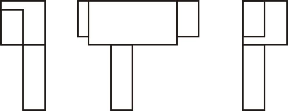
                  You question the value of knowing the projection. This example shows a front bview and two side views of a part:

                  conundrum.jpg

                  If you don't know whether this is first or third angle, you can't tell which of two possible shapes the object is.

                  Now think of something complex like a real car engine block, or a house… actually the simpler the part, the greater the chances of an error.

                  Neil

                  Edited By Stub Mandrel on 19/09/2012 21:04:25

                  #98837
                  jason udall
                  Participant
                    @jasonudall57142

                    Welll….looks like view on left of main view is wrong…but the point is correct….A knoledge of the system in use is as much a part of the drawing as any view.


                    Now try and complete the side view of the followingdrawing1.jpg


                    Edited By jason udall on 19/09/2012 23:37:49

                    #98847
                    Terryd
                    Participant
                      @terryd72465

                      "How silly is that?? Its the same diagram, just rearranged. No wonder its confusing cos as a novice you are looking for something much more complicated."

                      Hi Wolfie,

                      Here is a drawing of a simple component.  Projection method (1st or 3rd) is not specified. Does it matter?  Draw me a 3D sketch and post it here.


                      projection example.jpg


                      Best regards

                      Terry

                      Edited By Terryd on 20/09/2012 07:12:42

                      #98852
                      Terryd
                      Participant
                        @terryd72465
                        Posted by jason udall on 19/09/2012 23:24:36:

                        Welll….looks like view on left of main view is wrong…but the point is correct….A knoledge of the system in use is as much a part of the drawing as any view.


                        Now try and complete the side view of the followingdrawing1.jpg


                        Edited By jason udall on 19/09/2012 23:37:49


                        Hi Jason,

                        This has been covered in a another thread some time ago


                        jasons example.jpg

                        The first 4 possible solutions are third angle while the last is in 1st angle.

                        There are actually an infinite number of theoretical siolutions as the sloping face could be a curve and the central element can be either a cut out or a projection from the surfave and could be of almost any profile especially if hidden lines are excluded.

                        Interesting, classic example.

                        Best regards

                        Terry

                        Edited By Terryd on 20/09/2012 08:23:51

                        #98867
                        jason udall
                        Participant
                          @jasonudall57142

                          Terry.. Classic to us..new to others .. but yes .met it myself when 11….still stays with me today.

                          we had to also develope and build solid model ( back when that ment card knife and glue)

                          #98882
                          Wolfie
                          Participant
                            @wolfie

                            These problems are interesting but they are asking for the side view and not where to place it so are immaterial to the original question.

                            I have to say that I would have thought it was blindingly obvious to put the left hand side projection on the left, and the right hand side on the right, the top at the top and so on. Who would do it any other way???

                            "Hi Wolfie,

                            Here is a drawing of a simple component. Projection method (1st or 3rd) is not specified. Does it matter? Draw me a 3D sketch and post it here."

                            OK no doubt I have fallen for some trick here teeth 2 but here goes, being as you haven't included the top view I appreciate thet the rear may be different to the front  (not to scale)….


                            Edited By Wolfie on 20/09/2012 12:36:23

                            #98887
                            Terryd
                            Participant
                              @terryd72465

                              Qute:- "These problems are interesting but they are asking for the side view and not where to place it so are immaterial to the original question.

                              I have to say that I would have thought it was blindingly obvious to put the left hand side projection on the left, and the right hand side on the right, the top at the top and so on. Who would do it any other way??"


                              Hi Wolfie,

                              Firstly they are very relevant and your second statement seems to suggest that you have not understood that relevance, it is not simply about how views are located, it is about how they are placed relative to a hypothetical viewer of the component being drawn.  It is that which can lead to confusion between the two systems.

                              Your drawing is close, but not close enough. Notice the vertical lines on the elevations (solid and dashed) that should give you more of a clue, every line in an engineering drawing is important and ignored at ones peril. A person who can read engineering drawings does not really need a plan view here as it would not reveal any extra detail. and there is nothing that my drawings do not show, except the projection system (and of course dimensions), which is crucial to its accurate interpretation.  If extra detail is needed I would have drawn the plan view.

                              My Chief draftsman always insisted on economy as he viewed unnecessary drawing as a waste of time. As that great pioneering engineer Henry Maudslay said –

                              "Avoid complexities. Make everything as simple as possible." and

                              "Get rid of every pound of material you can do without; put to yourself the question, ‘What business has this to be there?"

                              A few designers in the pages of ME and MEW could do no better than to have this advice pinned over their workbenches.

                              By the way I will post a 3D sketch when you have had time to consider the above.

                              Best Regards

                              Terry

                              Edited By Terryd on 20/09/2012 13:16:12

                              #98888
                              Wolfie
                              Participant
                                @wolfie

                                OK lets try this then (Ignore the lack of drawing skills lol )

                                Edited By Wolfie on 20/09/2012 13:31:26

                                #98892
                                Terryd
                                Participant
                                  @terryd72465

                                  Hi Wolfie,

                                  Better, and half right. (drawing skills no problem, as long as you can put over an idea accurately it is inconsequential). Actually that is one possibility, however if you gave that to an engineer he would either wonder what the line down the centre of the top represents or conclude that it is two seperate components.

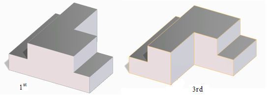
                                  These are the two possible solutions (there are others but more of that later) :-

                                  3d examples of projs..jpg

                                  If the drawing was in first angle proj. it would look like the example on the left (as you drew it, but rotated 180) the sketch on the right is what the component would look like in 3rd angle. Of course this is a simple example and would be explained with a plan view, but not all confusions are this simple and can lead to some real problems if the conventions are not understood and observed.

                                  The cut out could also be curved (e.g. quadrant) and that would also need a plan. I have though seen drawings in ME which have confused me until I realised that one side view was in first angle projection and the other in third angle crook. It is useful to understand the differences and be able to interpret drawings correctly to prevent expensive errors

                                  I was recently able to buy for pennies a rather nice piece of steel, about 20mm thick by 300mm wide and 450 mm long which had been accurately ground on both sides. The unfortunate machine operator had read the drawings wrongly (1st/3rd angle confusion) and made a very expensive piece of scrap – great for me, not so for him I believe.

                                  It's not just a pedantic exercise, believe me, when some use 1st angle and others 3rd angle projection systems. It would be good if we could all agree on one system but its a bit like the metric v imperial debate, but let's not go there – its Tiger country! wink

                                  Best regards

                                  Terry

                                  Edited By Terryd on 20/09/2012 14:27:57

                                  #98912
                                  Wolfie
                                  Participant
                                    @wolfie

                                    "Actually that is one possibility, however if you gave that to an engineer he would either wonder what the line down the centre of the top represents or conclude that it is two seperate components."

                                    The line is down the middle cos I couldn't work out how to rub just half of it out lol teeth 2

                                    Edited By Wolfie on 20/09/2012 17:29:00

                                    #98914
                                    Wolfie
                                    Participant
                                      @wolfie

                                      Actually I've just noticed summat. If you rotate those two solids 180º they swap projections. I drew your left hand one but I thought it was 3rd angle cos the end view was on the right.

                                      #99092
                                      nigel jones 5
                                      Participant
                                        @nigeljones5

                                        Now im convinced thats not right….have a look at this http://www.youtube.com/watch?v=_wDpN6Zi1hE

                                        #104683
                                        Ed Duffner
                                        Participant
                                          @edduffner79357

                                          I've wondered about these projections myself and to be honest can't see the point of having or using them. If a drawing is made clear enough with enough views of the part, why introduce a layer of confusion.

                                          The examples of the square inside another where you have to show the side view would never come up in real life surely? it would be an incomplete drawing yes?

                                          It's the same with off-side and near-side on a car, what happened to left and right?

                                          #104684
                                          blowlamp
                                          Participant
                                            @blowlamp
                                            Posted by Ed Duffner on 26/11/2012 12:40:33:

                                            I've wondered about these projections myself and to be honest can't see the point of having or using them. If a drawing is made clear enough with enough views of the part, why introduce a layer of confusion.

                                            The examples of the square inside another where you have to show the side view would never come up in real life surely? it would be an incomplete drawing yes?

                                            It's the same with off-side and near-side on a car, what happened to left and right?

                                            Left and right change, depending on if you're looking from the front or the rear. indecision

                                            Martin.

                                            #104699
                                            Gordon W
                                            Participant
                                              @gordonw

                                              Or ,of course left and right hand drive.

                                              #104707
                                              Mark C
                                              Participant
                                                @markc

                                                I thought I might add a bit to this – I have read the whole thread (but not all the links) and cannot find any mention to the link between CAD and 3rd angle.

                                                CAD is generally drawn 3rd angle (and I think there is mention of it being preferred in the old BS308) today unless there is a specific reason (locally) to do otherwise. It is done mainly due to a desire to make drawings un-ambiguous as has been stated before – disambiguation is the key to preventing scrap parts and wasted time/money along with recrimination about "who was to fault". As the parts get more complex, the greater the importance of the drawing layout – I have attached a drawing for a part that I drew to give an idea of how a modern CAD drawn part would be produced. It is not complete in the sense that there are a number of extra "sheets" to fully detail it along with a file containing the 3D solid geometry for direct import into the machine center (saved as "as cast" geometry including shrinkage and machining allowances). You will notice the projection information (little cone) and the magic words "if in doubt, ask" which roughley translate to "on your bike, I am making it like this!"

                                                Mark

                                                snap hook assy.jpg

                                                #120079
                                                hawkeyefxr
                                                Participant
                                                  @hawkeyefxr

                                                  When i was doing my apprieticship in the 60's i had a spell in the drawing office, i was told one was the American view the other English view, Which was what i can't remeber now.

                                                  #120092
                                                  Alan Jackson
                                                  Participant
                                                    @alanjackson47790
                                                    Posted by hawkeyefxr on 17/05/2013 06:31:07:

                                                    When i was doing my apprieticship in the 60's i had a spell in the drawing office, i was told one was the American view the other English view, Which was what i can't remeber now.

                                                    I think 3rd angle projection is american and mostly used. If you ever got a ist angle (english) drawing it became misleading and you had to read it with care to avoid misinterpretation. The comment "If in doubt ask" was often cynically restated " If in doubt don't ask" you got no help from nobody.

                                                    Alan

                                                    #120114
                                                    M0BND
                                                    Participant
                                                      @m0bnd

                                                      I see a lot of German drawings – all 1st angle! They can catch you out because your eyes and brain get used to 3rd and the drawings look very weird.

                                                      I haven't followed or read all the posts on this thread but I was always taught 1st angle is to take the part and just roll it to the new view(to the left, right, top or bottom). For 3rd angle, pick up and place to the left, right, top or bottom. Hope this helps!

                                                    Viewing 25 posts - 51 through 75 (of 167 total)
                                                    • Please log in to reply to this topic. Registering is free and easy using the links on the menu at the top of this page.

                                                    Advert

                                                    Latest Replies

                                                    Home Forums Beginners questions Topics

                                                    Viewing 25 topics - 1 through 25 (of 25 total)
                                                    Viewing 25 topics - 1 through 25 (of 25 total)

                                                    View full reply list.

                                                    Advert

                                                    Newsletter Sign-up